Table of Contents
Advertisement
This Manual is Bookmarked
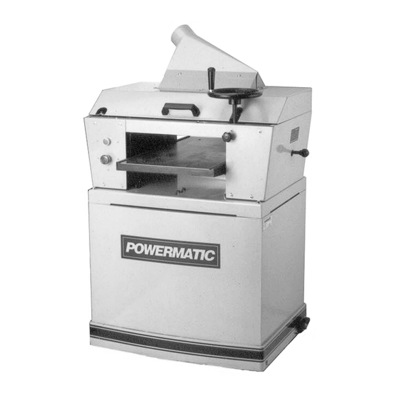
Operating Instructions and Parts Manual
15-inch Planer-Molder
Model PM15
*Manual Revision F for machines with serial number 0412PM15488 and higher
WMH TOOL GROUP, Inc.
2420 Vantage Drive
Elgin, Illinois 60124
Part No. M-0460264
Ph.: 800-274-6848
*Revision F 9/07
www.powermatic.com
Copyright © 2007 WMH Tool Group, Inc.
Advertisement
Table of Contents

Related Manuals for Powermatic PM15


Summary of Contents for Powermatic PM15
- Page 1 This Manual is Bookmarked Operating Instructions and Parts Manual 15-inch Planer-Molder Model PM15 *Manual Revision F for machines with serial number 0412PM15488 and higher WMH TOOL GROUP, Inc. 2420 Vantage Drive Elgin, Illinois 60124 Part No. M-0460264 Ph.: 800-274-6848 *Revision F 9/07 www.powermatic.com...
-
Page 2: Warranty And Service
This warranty covers only the initial purchaser of the product. WHAT IS THE PERIOD OF COVERAGE? The general POWERMATIC warranty lasts for the time period specified in the product literature of each product. WHAT IS NOT COVERED? The Five Year Warranty does not cover products used for commercial, industrial or educational purposes. Products with a Five Year Warranty that are used for commercial, industrial or education purposes revert to a One Year Warranty. -
Page 3: Table Of Contents
Parts List: Stand Assembly......................... 32 Stand Assembly..........................33 Parts List: Cutterhead, Hood and Table Assembly................34 Cutterhead, Hood and Table Assembly ....................36 Accessories: Knives and Moldings for PM15 Planer/Molder ..............37 Accessories: Knives and Moldings (cont.) ....................38 Electrical Connections ........................... 39... -
Page 4: Warning
Warning 1. Read and understand the entire owners manual before attempting assembly or operation. 2. Read and understand the warnings posted on the machine and in this manual. Failure to comply with all of these warnings may cause serious injury. 3. - Page 5 21. Make your workshop child proof with padlocks, master switches or by removing starter keys. 22. Give your work undivided attention. Looking around, carrying on a conversation and “horse-play” are careless acts that can result in serious injury. 23. Maintain a balanced stance at all times so that you do not fall or lean against the knives or other moving parts.
-
Page 6: Introduction
Introduction This manual is provided by WMH Tool Group, Inc. covering the safe operation and maintenance procedures for a Powermatic Model PM15 Planer-Molder. This manual contains instructions on installation, safety precautions, general operating procedures, maintenance instructions and parts breakdown. This machine has been designed and constructed to provide years of trouble free operation if used in accordance with instructions set forth in this manual. -
Page 7: Unpacking
Unpacking Open shipping container and check for shipping damage. Report any damage immediately to your distributor and shipping agent. Do not discard shipping material until Planer/Molder assembled running properly. Compare the contents of your container with the following parts list to make sure all parts are intact. -
Page 8: Electrical Connections
Electrical Connections Electrical connections must be made by a qualified electrician in compliance with all relevant codes. This machine must be properly grounded to help prevent electrical shock and possible fatal injury. This machine must be grounded. In the event of a malfunction or breakdown, grounding provides a path of least resistance for electric current to reduce the risk of electric shock. -
Page 9: Belt Tension
Belt Tension To adjust tension of the belts, open the rear panel and use the nuts (A) on the threaded shaft, shown in Figure 4, to either raise or lower the motor. Re-tighten nuts when satisfied. Proper tension is achieved when there is approximately 1/4”... -
Page 10: Depth Of Cut
Proper grinding done at the right time will do more than anything to prolong the life of knives. More dulling occurs in the last 20% of the useful life of the knife than in the other 80% of use. If the knives are sharpened on schedule and before the last 20% of possible use they can be resharpened with .002”... -
Page 11: Feed Rate
4. If the reading on the depth of cut scale is incorrect, loosen the two mounting screws on the clear plastic plate and adjust accordingly. The top scale (A, Fig. 8) is in English units, the bottom scale (B, Fig. 8) is metric. - Page 12 NOTE: If a bed and feed roll gauge is not available, use a finished block of wood with notches cut out for the table rollers, and a feeler gauge. See Figure 13 for an example of a wood block used as a gauge.) 2.
- Page 13 Chipbreaker The functions of the chipbreaker are to break chips into small pieces, help avoid splintering of the wood, help avoid board bounce on thinner boards, and to direct the flow of chips out of the machine. The chipbreaker is factory adjusted to be 1/32” below the cutting arc of the knives.
-
Page 14: Leveling Cutterhead With Bed
Leveling Cutterhead with Bed The cutterhead has been leveled with the surface of the planer bed at the factory. However, should future adjustment be needed, proceed as follows: 1. Place a bed and feed roll gauge (or wood block) beneath one end of the cutterhead. Crank the planer bed up until the cutterhead is just touching the gauge, and check the measurement. -
Page 15: Operation
Operation Kinds of Warp Warp is a variation from a plane or true surface. Warping of wood is caused by uneven shrinkage during the drying process. Shrinkage is not the same in all directions of the grain and due to the different grain direction in pieces of Figure 19 lumber, different types of warpage can occur. -
Page 16: Depth Of Cut
Depth of Cut The thickness of stock run through the planer is controlled by the distance you adjust the bed from the cutting knife. Always start your work by making a light planing cut. The depth of cut on subsequent passes may be increased, up to 1/8”, however, remember that a light cut creates a finer finish than a heavier cut. -
Page 17: Introduction To Molding
Introduction to Molding Pattern Knives Custom molding knives are ground from high speed hard steel. Your PM15 planer-molder will accept a single knife set, which uses gibs and counterbalances to ensure the cutterhead is in balance at all times. See Figure 24. It will also accept a three-knife set. -
Page 18: Homemade Guide Set-Up For Edge Molding
Homemade Guide Set-Up for Edge Molding Figure 27 shows a wooden guide set-up for edge molding. The guides are C-clamped on each side of the stock and are within 3/4” of the top edge to provide maximum support so that the narrow stock will travel beneath the knife. -
Page 19: Pattern Knife Clearance
3. Mount the molding cutter gauge (A, Fig. 31) to the theaded hole in the casting with the socket head cap screw (B, Fig. 31). The guide may be attached to either side. 4. Adjust the gauge (A, Fig. 31) so that the end of it meets the pattern knife, then tighten the screw (B, Fig. -
Page 20: Face Molding With Pattern Knives
1. To adjust the guides, lower the bed and place a board of correct width to be molded under the cutterhead. 2. Loosely adjust the guides to the board. Rotate the cutterhead by hand and see if the pattern knife will line up with the board. Adjust accordingly until the pattern knife and board are lined up as in Figure 33. -
Page 21: Common Molding Applications
If you have not already done so, install counterweights in the remaining two cutterhead slots. The rabbet knife is locked in place with the aluminum gib provided. NOTE: When the rabbet knife becomes dull on side, move rabbet knife counterweight set-up to the opposite side of the cutterhead. -
Page 22: Maintenance
Multiple Custom Knife Use Many operators who have continuous short runs of several different patterns save set-up time by installing more than one set of knives in the cutterhead at the same time. You can change from one pattern to another simply by changing the guides. -
Page 23: Lubrication
Lubrication 1. The recommended lubrication for roller chains used in medium to slow speed operation is to simply wipe the chain clean. When there is an appreciable build up of dust, dirt or wood shavings, use an oil cloth but never pour the oil directly on the chain. Over-oiling defeats the purpose of the lubrication, since it tends to invite the collecting of dust, shavings, etc. - Page 24 Trouble Probable Cause Remedy Machine will not Unit not plugged in. Verify unit is connected to power. start/restart or Place hood in down position to repeatedly trips Hood not in down position. engage interlock switch. circuit breaker or blows fuses. Check to determine if switch is actuating by listening for the audible click as hood is closed.
- Page 25 Trouble Probable Cause Remedy Examine the switch and switch housing for any sign of damage. If Machine will not damage is seen, replace components. start/restart or If the switch circuitry is suspect, you repeatedly trips Failed or broken interlock switch. have two options: have a qualified circuit breaker or electrician test the switch for function,...
- Page 26 Troubleshooting: Operating Problems Trouble Probable Cause Remedy Dull knives Sharpen or replace knives. Inadequate support of long boards. Use extensions to support boards. Snipe Adjust feed roller tension. Uneven feed roller pressure front to (Note: Snipe can not be back. eliminated, but can be so minimized as to become negligible.)
-
Page 27: Replacement Parts
Replacement parts are listed on the following pages. To order parts or reach our service department, call 1-800-274-6848, Monday through Friday (see our website for business hours, www.powermatic.com). Having the Model Number and Serial Number of your machine available when you call will allow us to... -
Page 28: Parts List: Base Assembly
Parts List: Base Assembly Index No. Part No. Description Size 1....6286639....Round Head Screw ........M6 x 10.P x 12Lg....26 2....6296220....Washer............. 6mm x 13 x 1T ....19 3....6296221....Hex Cap Screw ........M8 x 1.25P x 70Lg....4 4.... -
Page 29: Base Assembly
Base Assembly... -
Page 30: Parts List: Gearbox Assembly
35..... TS-1503071 .....Socket Head Cap Screw......M6 x 1.0P x 30Lg....1 36..... TS-1503051 .....Socket Head Cap Screw......M6 x 1.0P x 20Lg....1 37..... PM15-237 ....Shaft ....................1 38..... PM15-238 ....Hanger ....................1 39..... SB-5MM....Steel Ball..........5mm ........1... -
Page 31: Gearbox Assembly
Gearbox Assembly... -
Page 32: Parts List: Stand Assembly
Parts List: Stand Assembly Index No. Part No. Description Size 1....TS-1490031 .....Hex Cap Screw ........M8 x 1.25P x 20Lg....1 2....TS-1551061 .....Lock Washer ..........8mm ........5 3....6296175....Special Washer ........8mm x 32 x 4T ..... 1 4.... -
Page 33: Stand Assembly
Stand Assembly... -
Page 34: Parts List: Cutterhead, Hood And Table Assembly
Parts List: Cutterhead, Hood and Table Assembly Index No. Part No. Description Size 1....6286490....Socket Head Cap Screw......M6 x 1.0P x 15Lg....23 2....TS-1551041 .....Lock Washer ..........6mm ........18 3....6296169....Left Support Plate................. 1 4....6296170....Washer............. 6mm x 13 x 2T ....10 5.... - Page 35 58..... 6296210....Sprocket....................2 59..... 6296211....S-Ring............STW-17 ....... 2 60..... 6296212....Limiter ....................1 61..... TS-1521021 .....Set Screw..........M4 x 0.7P x 6Lg....1 62..... 6296214....Middle Table..................1 63..... 6296215....Handle Assembly.................. 1 64..... 6296216....Handwheel ................... 1 65..... 6296217....Hex Cap Screw ........M6 x 1.0P x 20Lg....1 66.....
-
Page 36: Cutterhead, Hood And Table Assembly
Cutterhead, Hood and Table Assembly... -
Page 37: Accessories: Knives And Moldings For Pm15 Planer/Molder
Accessories: Knives and Moldings for PM15 Planer/Molder... -
Page 38: Accessories: Knives And Moldings (Cont.)
Accessories: Knives and Moldings (cont.) -
Page 39: Electrical Connections
Electrical Connections... - Page 40 WMH Tool Group, Inc. 2420 Vantage Drive Elgin, Illinois 60124 Phone: 800-274-6848 www.wmhtoolgroup.com...
Need help?
Do you have a question about the PM15 and is the answer not in the manual?
Questions and answers