Table of Contents
Advertisement
Quick Links
Advertisement
Table of Contents

Related Manuals for Powermatic PM2020


Summary of Contents for Powermatic PM2020
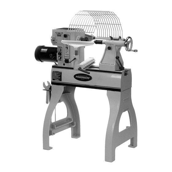
- Page 1 This .pdf document is bookmarked Operating Instructions and Parts Manual Woodturning Lathe 20” x 20” Model PM2020 Powermatic 427 New Sanford Road LaVergne, Tennessee 37086 Part No. M-1792020 Ph.: 800-274-6848 Revision A1 11/2017 www.powermatic.com Copyright © 2017 Powermatic...
-
Page 2: Warranty And Service
1.0 Warranty and Service Powermatic warrants every product it sells against manufacturers’ defects. If one of our tools needs service or repair, please contact Technical Service by calling 1-800-274-6846, 8AM to 5PM CST, Monday through Friday. Warranty Period The general warranty lasts for the time period specified in the literature included with your product or on the official Powermatic branded website. - Page 3 16.1.1 PM2020 Headstock Assembly – Exploded View ................. 26 16.1.2 PM2020 Headstock Assembly – Parts List ..................27 16.2.1 PM2020 Stand and Bed Assembly – Exploded View ................29 16.2.2 PM2020 Stand and Bed Assembly – Parts List ................... 30 16.3.1 Bed Extensions –...
-
Page 4: Safety Warnings
If used for other purposes, other conditions that may affect its operation. Powermatic disclaims any real or implied A guard or other part that is damaged should warranty and holds itself harmless from any be properly repaired or replaced. -
Page 5: Introduction
4.0 Introduction This manual is provided by Powermatic covering the safe operation and maintenance procedures for a Model PM2020 Lathe. This manual contains instructions on installation, safety precautions, general operating procedures, maintenance instructions and parts breakdown. This machine has been designed and constructed to provide consistent, long-term operation if used in accordance with instructions set forth in this manual. -
Page 6: Specifications
Shipping ........................... 609 lb (277 kg) The above specifications were current at the time this manual was published, but because of our policy of continuous improvement, Powermatic reserves the right to change specifications at any time and without prior notice, without incurring obligations. -
Page 7: Unpacking
6.1 Contents of shipping container 6.0 Unpacking Lathe Bed, with Headstock, Tailstock, & Tool Open shipping container and check for shipping Support Base – (A) damage. Report any damage immediately to your Leg Assemblies – (B) distributor and shipping agent. Do not discard any Guard –... -
Page 8: Assembly
Exposed metal areas of the Lathe, such as the 7.0 Assembly bed and spindles, have been factory coated with a protectant. This should be removed with Tools required for assembly a soft cloth and a cleaner-degreaser. Clean the bed areas under the headstock, tailstock 14mm wrench and tool support base. -
Page 9: Bed Extension (Optional Accessory)
(Figure 7), and screw it into the hole at the end number 6294727B, is available for the Lathe (see of the bed extension. your Powermatic dealer). To mount the bed extension to the Lathe: Slide the tailstock away from the edge of the... -
Page 10: Shelf Assemblies (Optional)
For outboard turning, where the headstock is moved to the opposite end of the Lathe to accommodate large bowl blanks, you can (1) mount the 18” bed extension to the three lower holes on the Lathe frame, and (2) mount a vertical extension post [included with the optional bed extension] to the tool rest base. -
Page 11: Electrical Connections
Local codes take precedence over recommend- When all holes have been bored, place the 2x6’s on edge in the outer ledges of the Lathe. dations. Cut the dowel rods to length with a miter saw 8.1 Single Phase Operation or hand saw, so that after insertion the rods will be flush with the back of the rear 2x6. -
Page 12: Adjustments
9.0 Adjustments 9.1 Headstock and tailstock movement To slide the headstock or tailstock, swing the locking handle (A, Figure 13) backward or forward until the headstock/tailstock can slide freely. When the headstock/tailstock is positioned, rotate the locking handle to tighten it securely. To remove headstock, tailstock or toolrest base from the bed, unscrew and remove either of the stop bolts (B, Figure 13). -
Page 13: Live Center And Cone
9.5 Live center and cone The live center cone, shown in Figure 16, screws clockwise onto the threads of the live center body. To remove the cone from the live center, first insert the live center pin through the hole in the live center body as shown in Figure 16. -
Page 14: Face Plate: Installing/Removing
Figure 19 Figure 21 9.8 Face plate: installing/removing 9.9 Speed change Disconnect Lathe from power source. Disconnect Lathe from power source. Mount the face plate to your bowl blank. To change speed ranges, pull open the access door on the headstock. Push in the spindle lock button (Figure 20) and rotate the handwheel slightly until the spindle Loosen the pivot lock handle (A, Figure 22) -
Page 15: Checking Spindle Play
Do not over tighten the bearing lock nut or the spindle bearings will overheat. The bearing lock nut should be tightened just enough to remove the end play and the spindle should still rotate very freely. Run the lathe for a time, and check for heat from the spindle bearings. -
Page 16: Operating Controls
A.C. Inverter (mounted to rear of headstock) eliminate shadows and reduce eye strain. The PM2020 Lathe uses the latest technology in A.C. inverter drives to provide infinitely variable 11.2 Turning tools spindle speeds within the specified ranges (shown under sect. -
Page 17: Spindle Turning
Deep Fluted Bowl Gouge – 1/4", 3/8" and 1/2", Never allow the tool to rest in one place on the used for turning bowls & plates. wheel, keep it moving and use a light touch. Square Scraper (Bedan) – 3/8” or 1/2", used to Carbon steel tools can overheat easily and should create square shoulders. - Page 18 The tailstock ram is capable of exerting excessive pressure against workpiece and the headstock. Apply only sufficient force with the tailstock to hold the workpiece securely place. Excessive pressure can overheat center bearings and damage both workpiece and Lathe. 10. Move tool support into position. It should be parallel to the workpiece, just below the centerline and approximately 1/8"...
- Page 19 Figure 30 Figure 31 Keep as much of the bevel of the tool as "V" Cuts possible in contact with the workpiece to ensure control and avoid catches. NOTE: Always cut down-hill, or from large diameter to Use the long point of the skew. (NOTE: Do not small diameter.
-
Page 20: Face Plate And Bowl Turning
Sanding and Finishing NOTE: When using a waste block, be careful with the adhesive you select. Dry workpieces can be Leaving clean cuts will reduce the amount of bonded with ordinary white or yellow glue but must sanding required. Move the tool support out of the be clamped to ensure a good bond. - Page 21 having it in the finished piece. Most checks radiate control, use your whole body to move the from the pith. gouge through the workpiece. As you turn bowls from green wood, make sure As the bowl takes shape, work on the bottom maintain consistent wall...
-
Page 22: Maintenance
Maintenance on the PM2020 Lathe should be to maintain a clean even curve. As the tool performed at periodic intervals to ensure that the... -
Page 23: Indexer Positions
13.0 Indexer positions How to use the chart The indexer is shown as viewed from the tailstock end of the Lathe. Points A, B, C and D are the holes in the head casting. The holes in the spindle collar may be considered as numbered 1 through Example: You wish to rout 9 flutes on your spindle blank. -
Page 24: Troubleshooting The Pm2020 Lathe
14.0 Troubleshooting the PM2020 Lathe Trouble Probable Cause Remedy * Motor fails to develop Power line overloaded. Correct overload condition. full power. Undersize wires in power supply Increase supply wire size. system. Faulty inverter. Contact Powermatic Technical Service. Worn motor. -
Page 25: Replacement Parts
15.0 Recommended lathe speeds (per diameter of workpiece) Diameter of Work Roughing RPM General Cutting RPM Finishing RPM Under 2” 1520 3000 3000 2” to 4” 1600 2290 4” to 6” 1080 1500 6” to 8” 1125 8” to 10” 10”... -
Page 26: Pm2020 Headstock Assembly – Exploded View
16.1.1 PM2020 Headstock Assembly – Exploded View... -
Page 27: Pm2020 Headstock Assembly – Parts List
16.1.2 PM2020 Headstock Assembly – Parts List Index No. Part No. Description Size 1 ....6294736 ....Faceplate ..............3” ........1 2 ....6295796 ....Nyloc Insert Socket Set Screw ........ 1/4-20x3/8” ....4 3 ....6294725 ....Spur Center ............. MT2 ......1 4 .... - Page 28 Index No. Part No. Description Size 59 ....3601006 ....Spindle Lock Plunger ..................1 60 ....3520B-260 ....Control Label ....................1 61 ....6294786 ....Spindle Lock Bracket ..................1 62 ....6077228 ....Micro V-Belt ............. 260J ......1 63 ....
-
Page 29: Pm2020 Stand And Bed Assembly – Exploded View
16.2.1 PM2020 Stand and Bed Assembly – Exploded View... -
Page 30: Pm2020 Stand And Bed Assembly – Parts List
16.2.2 PM2020 Stand and Bed Assembly – Parts List Index No. Part No. Description Size 1 ....2020-101 ....Bed ........................ 1 2 ....3520B-102 ....Leg ......................... 2 3 ....6295754 ....Stop Bolt ......................2 .... -
Page 31: Bed Extensions – Exploded View (Optional Accessory)
16.3.1 Bed Extensions – Exploded View (optional accessory) 16.3.2 Bed Extensions – Parts List (optional accessory) Index No. Part No. Description Size ....6294727B ....18” Bed Extension Assembly (includes items 1 thru 6) 1 ....3520B-310 ....Extension Post ....................1 2 .... -
Page 32: Outboard Turning Stand – Exploded View (Optional Accessory)
16.4.1 Outboard Turning Stand – Exploded View (optional accessory) 16.4.2 Outboard Turning Stand – Parts List (optional accessory) Index No. Part No. Description Size Qty....6294732 ....Heavy Duty Outboard Turning Stand Assembly (items 1 thru 7) ...... 1 ....3042503 ....Turning Stand Base ..................1 2 .... -
Page 33: Optional Accessories: Face Plates, Tool Supports And Misc
16.5 Optional Accessories: Face Plates, Tool Supports and Misc. Index No. Part No. Description Size Qty. 1 ....6295902 ....Ball Bearing Tailstock Center (not shown) . 2 ....6294736 ....3” Face Plate ..........1-1/4-8 .......... 3 ....6294733 ....Remote ON/OFF Switch ................... 4 .... -
Page 34: Electrical Connections
17.0 Electrical connections... -
Page 35: Electrical: Remote On/Off Switch (Optional Accessory)
18.0 Electrical: Remote On/Off Switch (optional accessory) NOTE: The Lathe can only operate when both the headstock and remote switches are in the “ON” position. To mount the remote switch to your Lathe, proceed as follows. Disconnect all electrical power to the Lathe. Remove the two screws from the control panel. - Page 36 427 New Sanford Road LaVergne, Tennessee 37086 Phone: 800-274-6848 www.powermatic.com...
Need help?
Do you have a question about the PM2020 and is the answer not in the manual?
Questions and answers