
Related Manuals for Oricom UHF100


Summary of Contents for Oricom UHF100
-
Page 1: Operating Instructions
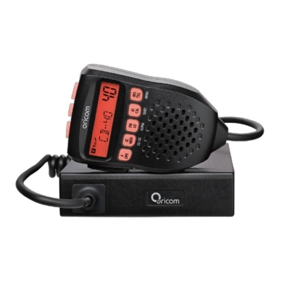
UHF100 UHF200 Operating Instructions For UHF100 and UHF200 40 Channel UHF 2-way Citizen Band Radio Downloaded from www.cbradio.nl... -
Page 3: Table Of Contents
Table of contents Table of contents ................3 Safety Information and Warnings ..........4 Controls and Connectors ...............5 Installation ..................10 Operations ..................14 UHF channels and frequencies ............30 Warranty information (Australia) ..........33 This unit complies with all relevant Australian and New Zealand approval requirements. -
Page 4: Safety Information And Warnings
Safety Information and Warnings Please read before installing or opearating Your Oricom Radio The operation of this radio in Australia and New Zealand is subject to conditions in the following licenses. In Australia the ACMA Radio communications (Citizen Band Radio Stations) and in New Zealand by MED General User Radio License for Citizen Band Radio and operation is subject to conditions contained in those licences. -
Page 5: Controls And Connectors
1 x Mount bracket with mounting screw for Remote Head Unit 1 x Remote Head Unit with 2m cable 1 x Microphone Hanger 1 x UHF100 Standard Microphone 1 x User Guide 1 x DC Power Cord with inline fuse 1 x Mounting bracket with mounting... - Page 6 Controls and Connectors Front View Remote Head unit (UHF100) 1. Microphone connector 6. Priority Channel On/Off, Key Lock On/Off, Alpha-numeric display 2. LCD Display 7. ID setting, 5 tone SelCall, Quiet 3. Power On/Off, channel & Volume control 8. Monitor, TSQ On/Off, Menu 4.
-
Page 7: Rear View
Controls and Connectors Rear View Rear view of Radio (UHF100 & 200) 1. 3.5mm external jack for optional 8 ohm speaker 2. Power Supply connection 3. Antenna connection Standard Microphone (UHF100) 1. Push To Talk (PTT) button 2. Volume Up, Channel Up 3. - Page 8 Controls and Connectors Top view of Contoller Speaker Microphone (UHF200) 1. Volume Down, Channel Down 2. Volume Up, Channel Up 3. Power On/Off 200RX Front view of Contoller Speaker Microphone (UHF200) 4. LCD Display 5. Function button & Duplex On/Off 6.
- Page 9 Controls and Connectors LCD Icons & Indicators (UHF100 and UHF200) 10. Open Scan 1. FUNCTION 2. RX or TX Signal strength 11. Group Scan 3. Transmitter Indicator 12. Selelctive call Sending_to 4. Receiver Indicator 13. Selective call Receiving from 5. Quiet mode 14.
-
Page 10: Installation
The radio contains a built-in loud speaker, The radio can be installed ‘out of the way’ and an external speaker can be used as an alternative (not supplied). To mount the Remote Head (UHF100) The remote head is supplied with a slim mounting bracket and thumb screws. - Page 11 Installation 1. Fix the mounting bracket in place by screwing through the slots in the bracket. 2. Fix the remote head unit to the mounting bracket with the thumb screws provided. 3. Connect the standard microphone to the remote head socket, and tighten up the thumb screw.
- Page 12 Controller Speaker Microphone; part number, CSPKMIC Standard Microphone; part number, MIC050 These can be purchased from the dealer you purchased the radio from or directly from Oricom. DC Power Connection The Radio is designed for 13.8 Volt DC, negative earth installations only (i.e.
-
Page 13: Antenna Information
If required you may install an external (8 ohm, max 5w power) speaker fitted with a 3.5mm plug (not supplied). There is a jack located on the rear of the radio and on the UHF100 there is an additional jack on the side of the remote head unit. -
Page 14: Operations
Operations Power on and off * Press and hold the PWR button on the UHF100 Remote Head or the UHF200 microphone PWR button for 2 seconds. * The default channel is set at CH01. 200RX 200RX UHF100 UHF200 Volume control * The UHF100 has a rotary electric volume control. - Page 15 Operations 200RX 200RX blinking Tri Function buttons To use the primary function (F, SC, PRI, ID, MO) press the required button. To use the secondary function (DPX, MEM, LO, CAL, TSQ) press and hold the button for 2 seconds. To use the third function (OS/GS, ALPHA, QUIET, MENU), press F/DPX and press the required button.
-
Page 16: Priority Channel
Operations Priority Channel To store a Priority Channel, press the PRI/LO button. The letter "P" will appear when the priority channel is set. The channel you selected as your Priority Channel will then be automatically monitored during the Group Scan. Note: You can only store one channel as your priority channel. - Page 17 Operations Selecting the Required CTCSS Tone To pre-select the CTCSS tone on your radio, please refer to the MENU settings on page 24. Enabling CTCSS on a Channel If a CTCSS tone has been selected, it can be enabled on individual channels. 1.
-
Page 18: Group Scan
Operations Open Scan Group Scan With Group Scan the Radio scans for activity, but in addition, it also inserts your Priority Channel into the scan sequence. This means that your Priority Channel will be monitored regularly while scanning to ensure that no calls are missed. Any signals received on your Priority Channel will take precedence over any signals received on the other channels. - Page 19 1. Press the ID/CAL button to select the CALL TO mode. 2. To select the required Identity in memory locations 'C0' to 'C9'. Rotate the channel knob on the front display of the UHF100. And, for the UHF200 press the Channel Up and Channel Down buttons on the microphone.
- Page 20 Operations Entering, Editting and Storing a Selcall Name or ID number 1. Briefly press the ID/CAL button. The CALL TO mode will be selected and the last-sent Selcall memory location will be displayed. 2. Rotate the Channel knob to select the required Selcall memory (locations C0 to C9).
- Page 21 Operations To return the call Press F/DPX and hold the ID/CAL button for 2 seconds until the radio beeps. The callers Selcall Identity will be sent to the caller. Cancelling the Selcall Alert To cancel the alarm and talk on the channel, press the PTT button. The alarm will be cancelled and the channel will be open for normal communication.
- Page 22 Operations To call the group, program the Base radio Group ID code to 1234A. When you call the group, all of the above vehicles will receive the Group Calling Tone. Group call IDs can be stored in memory the same way as a Standard Selcall ID code, please refer to Entering, Editing and Storing a Selcall ID number at page 10 Radios 100 Radios...
- Page 23 Operations Setting up QUIET Mode To setup QUIET mode you must first ‘tag’ the channels that you want to stay quiet, then activate the QUIET mode. Once QUIET mode is activated, the channels you have tagged will remain quiet to all incoming signals unless your Selcall Ident is received.
- Page 24 Operations Third functions MENU list * Use the channel knob to change the value of each setting. * Use the Scan button to select the next function. * If a button is not pressed within 8 seconds the Radio will automatically exit the menu mode.
- Page 25 Operations SQL: The radio has 8 preset ( off - 7) squelch levels: off - SQ off (monitor on condition) 1 - Max sensitivity (min squelch) 7 - min sensitivity (max/tight squelch) CTCSS and DCS setting This feature allows you to receive signals only from callers who have selected the same CTCSS and DCS code.
-
Page 26: Duplex Operation
Operations Duplex Operation General Your radio has a Repeater Access function to allow use of local Repeater stations (if available in your area). Repeaters are shared radio system installed by interested parties (clubs, local business etc.) that pick transmissions on specific channels and re-transmit (or repeat) the received signal to another channel. -
Page 27: Key Lock
If you transmit on CH01 duplex mode, you are actually transmitting on CH31 the repeater station down converts your signal and retransmits on CH01. Your UHF100 and UHF200 allows you to pre-select Duplex operation individually on each channel. Push and hold the F/DPX button for 2 seconds, "DPXON" should appear on the LCD. - Page 28 Operations 200 Receive (RX) only Channels Manual Programming The UHF Radio has a wide band search feature which will allow you to search Frequencies ranging from 400-512MHz (in 12.5KHz steps). You may search the full range or you may search one of 4 smaller bands separately. Turn power on.
- Page 29 Operations * press the PRI/LO button, next 2 digits will be blinking for the next frequency digits. * Rotary channel switch to select which 2 frequency digits you want. Briefly press the F/DPX button and Power button to exit. Automatic programming 1.
-
Page 30: Uhf Channels And Frequencies
UHF channels and frequencies Channel Frequency Table Radiocommunications (Citizen Band Radio Stations) Class Licence 2002 No licence is required to own or operate this radio in Australia and New Zealand. The Radiocommunications (Citizen Band Radio Stations) Class Licence 2002 contains the technical parameters, operating requirements, conditions of licence and relevant standards for Citizen Band (CB) radios. - Page 31 UHF channels and frequencies 476.775 Simplex 476.800 Simplex 476.825 Simplex 476.850 Simplex 476.875 Simplex 476.900 Simplex 476.925 Simplex 476.950 No Use 476.975 No Use 477.000 Simplex 477.025 Simplex 477.050 Simplex 477.075 Simplex 477.100 Simplex 477.125 Simplex 477.150 Simplex 477.175 Duplex TX/Simplex 477.200 Duplex TX/Simplex 477.225...
- Page 32 UHF channels and frequencies Channel 11 is a calling channel generally used to call others and channel 40 is the customary road vehicle channel. Once contact is established on the calling channel, both stations should move to another unused "SIMPLEX" channel to allow others to use the calling channel. Channel 22 and 23 are for Telemetry and Telecommand use, voice commnuications are not allowed on these channel by law.
-
Page 33: Warranty Information (Australia)
Spare parts may be new or equivalent to new. Spare parts are warranted to be free from defects in material or workmanship for thirty (30) days or for the remainder of the Warranty Period of the Oricom branded product in which they are installed, whichever is longer. - Page 34 Oricom does not warrant that the operation of the product will be uninterrupted or error free. Oricom is not responsible for damage that occurs as a result of your failure to follow the instructions that came with the product.
-
Page 36: Customer Support
New Zealand - www.oricom.co.nz - Email our customer support team on support@oricom.com.au - Contact Oricom Customer Support team on 1300 889 785 or 02 4574 8888 (Monday to Friday 9am to 5pm EST) Please retain your purchase receipt and attach to the back page of this user guide.
Need help?
Do you have a question about the UHF100 and is the answer not in the manual?
Questions and answers