
Related Manuals for ProVisual H Series


Summary of Contents for ProVisual H Series
-
Page 1: User Manual
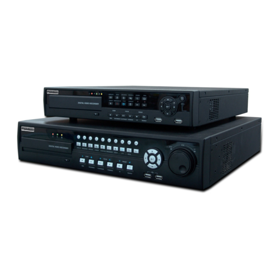
ProVisual Standalone Digital Video Recorder ProVisual DVR Series H / FH / MH / VH / AQH 4 / 8 / 16 Channel Models User Manual This document contains preliminary information and is subject to change without notice. -
Page 2: The Equipment Complies With The Requirement Of Fcc Cfr 47 Part 15 Subpart B, Class A
FCC Compliance Statement Notice to Users This equipment has been tested and found to comply with the limits for a Class A digital device. Pursuant to Part 15 of the FCC Rules, these limits are designed to provide reasonable protection against harmful interference when the equipment is operated in a commercial environment. -
Page 3: Cautions
Cautions This product has free voltages (100V and 240V). See installation instructions before connecting to the power supply. This product uses a Lithium battery. To avoid any risk of explosion, do not replace the battery on the main board by anything other than a Lithium battery. ... - Page 4 12. Servicing Do not attempt to service this equipment yourself. Refer all servicing to qualified service personnel. 13. Damage Requiring Service Unplug this equipment from the wall outlet and refer servicing to qualified service personnel under the following conditions: ①...
- Page 5 The List of Configuration ProVisual H Series DVR : 4 / 8 / 16CH DVR Set ProVisual FH / MH / AQH Series DVR : 4 / 8 / 16CH CD (ProVisual CMS Pro/Manual) Remote Controller Screws HDD Brackets Rack Bracket...
-
Page 6: Operation Precautions
Operation Precautions Power Off Do not turn DVR off, or plug off the power adapter while DVR is in operation (record/playback). Otherwise, it may cause permanent damage to the equipment. Please click ( ) SETUP>SYSTEM>Shutdown sequentially and then remove the power after DVR is shutdown completely. -
Page 7: Table Of Contents
PROVISUAL DVR-16214-AQH ................ 20 2.2.2 Monitor Connections (Video Out, VGA and Spot)......20 SETUP ......................30 2.2.3 HDMI connections (ProVisual DVR MH / VH / AQH Series ) ... 20 2.2.4 Audio Connections ..............21 SYSTEM LOG ....................31 2.2.5 TCP/IP(Ethernet) Connections .......... - Page 8 4.3.5 Multi Spot(ProVisual MH / VH Series DVR) ......41 4.3.6 VGA ( ProVisual H / FH / MH / VH / AQH ) ....... 42 PROVISUAL DVR-412-AQH / DVR-824-AQH / DVR-1648-AQH ....56 DEVICES .................... 43 PROVISUAL DVR-400-AQH ................56 4.4.1...
- Page 9 PROVISUAL H / FH SERIES DVR ............62 8.5.2 HDD connections and Operating Status ........84 8.5.3 Recording Status............... 85 PROVISUAL MH / VH /AQH SERIES DVR ..........62 5.1.4 Freeze Live Image ..............62 8.5.4 Motion Recording Status ............85 5.1.5...
- Page 10 12.1.3 Site Registration ..............103 12.4.6 Information ................124 12.1.4 Connection ................104 12.4.7 Disconnection ..............124 12.1.5 Search ................. 105 12.4.8 Uninstallation ..............124 12.1.6 PTZ Control ................. 106 12.5 Windows Mobile ................125 12.1.7 Information ................107 12.5.1 System Requirements ............
-
Page 11: Product Features
: Power Supply Cable - Remote Control With 2 AAA batteries - Installation CD (CMS / ProVisual CMS Pro Software & User’s Manual) 1.2 Service If there is any problem in the product, please refer servicing to a supplier or a distributor with qualified service personnel. - Page 12 ProVisual DVR-824-FH / DVR-1648-FH...
- Page 13 ProVisual DVR-824-MH / DVR-1648-MH...
- Page 14 ProVisual DVR-824-VH / DVR-1648-VH...
- Page 15 ProVisual DVR-412-AQH / DVR-824-AQH / DVR-1648-AQH HD-SDI DVR...
- Page 16 ProVisual AQH Series – DVR-400-AQH 4 Channels DVR...
- Page 17 ProVisual – DVR-16214-AQH 16 Channels Hybrid DVR...
-
Page 18: Installation
- Please mount DVD-RW at the SATA 4 port. ProVisual MH / VH / AQH Series DVR - Main substrate of this DVR has five SATA ports: they are indicated as SATA 1, 2, 3, 4 and SATA 5. -
Page 19: Hdd Installation
‘HDD’ item. When the Remove procedure is completed, DVR will auto-reboot. 2.1.5 Maximum HDD Capacity Each model has a different HDD capacity recognition. Below table shows the recommended maximum HDD capacity for each model. Model H Series FH Series MH Series VH Series AQH Series Capacity... -
Page 20: Dvd-Rw Installation
2.2.3 HDMI connections ( ProVisual DVR MH / VH / AQH Series Connect HDMI cable to HD out port of rear panel and HDMI port of HD output device. Please click ( ) SETUP> DISPLAY> VGA and the following screen will appear. -
Page 21: Audio Connections
2.2.11 Power Supply connections ProVisual DVR H Series : Plug the power supply adapter (DC 12V, 5A) which include in this product to ’DC12V’ connector and plug another side to power source. Adapter input voltage is a free volt (100 VAC ~ 240 VAC). Please do not... -
Page 22: Connections Guideline
DVR to malfunction. ProVisual FH / VH / MH Series : Plug the power supply adapter (DC 12V, 6.67A) which include in this product to ’DC12V’ connector and plug another side to power source. Adapter input voltage is a free volt (100 VAC ~ 240 VAC). -
Page 23: Input Device And Screen Icons
3. Input Device and Screen Icons 3.1 Key and LEDs ProVisual H Series DVR KEYS PTZ KEY Operating mode Setup mode •Up/Down/Left/Righ ▲, ▼, ◄, ► • Control Pan/Tilt rotation of up/down/left/right in PTZ mode t on screen cursor control 1 ~ 10 •... -
Page 24: Provisual Fh / Mh / Vh / Aqh Series Dvr
ProVisual FH / MH / VH / AQH Series DVR KEYS PTZ KEY Operating mode Setup mode •Up/Down/Left/Righ ▲, ▼, ◄, ► • Control Pan/Tilt rotation of up/down/left/right in PTZ mode t on screen cursor control 1 ~ 16 • Camera select keys : (4/8/16 channel DVR) DISPLAY •... -
Page 25: Camera Select Keys For 16 Channel Dvr
Below shows how to select camera channel for 16hannel Select Camera No. 10~16: press key and use , 1~6 key ProVisual FH / MH / VF / AQH Series DVR Below shows how to select camera channel for 4/8/16channel DVR ... -
Page 26: Channels Dvr
8 Channels DVR 16 Channels DVR ProVisual FH / MH / VF / AQH Series 4 Channels DVR Channels DVR Channels DVR 3.4 Using a Remote Controller Usage of a remote controller is same as the front panel keys. -
Page 27: Using A Mouse
3.5 Using a Mouse Mouse provides an easier access to adjustment. Refer to below for proper use. Left mouse button functions the same as Enter ( ) key on the front panel of DVR. Right mouse button displays the following “Function keys” on screen. ... -
Page 28: Screen Icon
3.6 Screen Icon Icon Description Icon Description Continuous recording mode In Audio recording Event recording mode CMS access indication/ No. of accesses (Alarm In/Motion) (up to 4) In recording In channel sequencing PTZ registration / PTZ mode Lock Remote Controller Setup in HDD Overwrite mode Setup in HDD No Overwrite mode Setup in HDD No Overwrite mode... -
Page 29: Setup
4. Setup 4.1 Login / Logout At the default setting of DVR, user has to input the password to enter the set up menu. Please press SETUP key to enter the setup menu and the following screen will appear. ... -
Page 30: System
4.2 SYSTEM 4.2.1 Information Please click ( ) SYSTEM>Information and the following screen will appear. Status Site Description Decide on a name of DVR. Please click ( ) keyboard icon on Site Description frame and the following virtual keyboard will appear. ... -
Page 31: System Log
Import: Copy the Menu setup stored in USB memory stick into DVR. Please plug in the memory stick and then click ( ) Import. Export: Store the Menu setup of DVR in USB memory stick. Please plug in the memory stick and then click ( ) Export. ... -
Page 32: Clear All Data
User shall designate the total recording days from 1 day to 30 days and unlimited. User may set for beeping or notifying messages that notify the used percentage of disk. Check Disk Overwrite and user may activate the overwrite function. - This function makes restart the recording from the beginning when the HDD is full. -
Page 33: Date
Please click ( ) SYSTEM>Admin and the following screen will appear. Date / Time Date This menu will allow user to adjust the settings. Please follow the procedure below for time adjustment. ① Click ( ) items (Y, M, D) to change. A designated item will be highlighted in a box (Y: Year, M: Month and D: Date). ②... -
Page 34: Time Format
Time Format Set time indication format. Please click ( ) Time Format frame to select a format from the list. When user complete Date/Time input, please click ( ) NTP and the following screen will appear. This menu is for accurate setting of time of day clock in DVR. ... -
Page 35: Format
- 3. External SATA 2 - 4. Internal SATA 5 Port - 5. DVD-RW (Note) Only ProVisual MH / VH /AQH Series DVR support e-SATA storage. Format User must format when: - install new HDD - add another HDD... -
Page 36: Account
HDD used in DVR. In general, it is 55°C. Click ( ) ▲, ▼ direction buttons on the right-hand side of HDD Damage frame to set the permissible level of HDD damage (%). HDD is a very crucial element for DVR recording, so set the permissible level within 1% to 2% to assure maximum safety. -
Page 37: Password Resetting
New User Please click ( ) New User and the following screen will appear. Click ( ) the keyboard icon on the right-hand side of User Name frame and the virtual keyboard will appear. Click desired characteristics (up to 8 characteristics) on the virtual keyboard. ... -
Page 38: System Log
This is a screen for password resetting. Input password by clicking the keyboard icon on the right-hand side of the frame. Use key if wish to erase password on keyboard. 4.2.4 System Log Please click ( ) SYSTEM>System Log and the following screen will appear. ... -
Page 39: Shutdown
4.2.6 Shutdown Shutdown is a function to help user safely turn the DVR off. Please use the proper shut down procedure to avoid damaging to our DVR system. Do not remove the power during shut down. CAUTION DO NOT TURN DVR OFF WITHOUT USING THE PROPER SHUT DOWN PROCEDURE. OTHERWISE, IT MAY CAUSE DAMAGE TO DVR. -
Page 40: De-Interlace
De-Interlace This function changes playback display into Progressive Scan or Interlace Scan. Check () De-Interlace, then frame will display as the Progressive Scan and shows the better picture quality. Transparency The Transparency menu will allow user to alpha-blending of OSD menu on the monitor. Transparency is the quality that an object or substance has when user can see through it. -
Page 41: Spot Monitor Control On Display Mode
Adjust the rotation interval of camera by clicking Dwell column. The rotation interval changes to 3>5>10>15>30>60 seconds by each press. ProVisual H / MH / VH / AQH Series DVR does not have a spot connection. 4.3.4 Spot Monitor Control on Display Mode ... -
Page 42: Vga ( Provisual H / Fh / Mh / Vh / Aqh )
4.3.6 VGA ( ProVisual H / FH / MH / VH / AQH Users are able to set its video output resolution from 1024x768 to 1920x1080 If user wishes to hear audio via HDMI cable, check the box HD Audio Output... -
Page 43: Devices
Users are able to set its video output resolution from 1024 x 768 to 1920 x 1080 If user wishes to hear audio via HDMI cable, check the box HD Audio Output HD-SDI DVR displays and records differently with previous NTSC or PAL methods. ... -
Page 44: Network Type
Network Type Please click ( ) Network Type. When you click ( ) the button, it changes alternately to Static (fixed IP) and DHCP (floating IP). In Static, user must manually set the static IP address for use. - Set IP Address, Subnet Mask and Gateway. - Page 45 Network video transmission speed and quality can be configured by pressing “Frames” and “Quality” buttons as follows. - Frames : H Series - 1, 2, 3, 4, 5, 7, 15 frames for NTSC (1, 2, 3, 4, 5, 6, 12.5 frames for PAL) H / FH / MH / VH /AQH Series DVR - 1, 2, 3, 4, 5, 7, 15, 30 frames for NTSC (1, 2, 3, 4, 5, 6, 12.5, 25 frames for...
-
Page 46: Camera / Ptz
CAUTION IT IS NOT ABLE TO CHANGE Port Number DURING CMS ACCESS TO DVR. CAUTION IF USERS WANT TO USE UPNP FEATURE, PLEASE NOTE THAT THE ROUTER HAS TO SUPPORT THE UPNP. CAUTION CHANGES BEING MADE ARE APPLIED AFTER COMPLETE SETUP TO EXIT. CAUTION ONCE PORT NUMBERS ARE CHANGED, IT MUST BE CHANGED THE PORT NUMBERS OF CMS (Central Monitoring Station) PROGRAM AS WELL. - Page 47 Click ( ) the keyboard icon on the right-hand side of each frame on Title column and the virtual keyboard will appear. Then, register titles of cameras. If a check box is checked on No column, a video of the corresponding camera is recorded and displayed on the monitor. However, if user does not check the checkbox, both recording and monitor display stop.
-
Page 48: Audio Bind To Cam
4.4.3 Audio Bind to cam Please click ( ) DEVICES>Audio and the following screen will appear. The Audio menu will allow user to choose whether to record Audio. When a check box is marked on No column, corresponding audio and video are recorded. However, if the check box is not marked, audio is not recorded. -
Page 49: Serial In
Click ( ) the keyboard icon on the right-hand side of each frame on Title column and the virtual keyboard will appear. Then, please register the title of Alarm output. When a check box is marked on No column, a corresponding Alarm output starts operating. However, if user does not check the check box, the operation stops. -
Page 50: Provisual H / Fh Series Dvr
Click ( ) each frame on Frames column to select recording rate of a corresponding camera. Recording rate varies by camera. Below lists the maximum recording rate of each camera. ProVisual H / FH Series DVR NTSC(PAL) 360x240 (360x288) -
Page 51: Provisual Dvr-400-Aqh
ProVisual DVR-400-AQH 360x 240(288) 720x240(288) 720x480(576) 1280 x 720 1920 x 1080 4 Channel DVR 120(100) 120(100) 120(100) ProVisual DVR-16214-AQH HD-SDI Input (CH 1~2) 360x 240(288) 720x240(288) 720x480(576) 1280 x 720 1920 x 1080 2 Channel 60(50) 60(50) 60(50) ... -
Page 52: Provisual H / Fh Dvr Series
ProVisual H / FH DVR Series NTSC(PAL) 360x240 (360x288) 720x240 (720x288) 720x480 (720x576) 4 Channel DVR 120 (100) 120 (100) 60 (50) 8 Channel DVR 240 (200) 120 (100) 60 (50) 16 Channel DVR 480 (400) 240 (200) 120 (100) -
Page 53: Provisual H / Fh Series Dvr
Click ( ) each frame on Frames column to select recording rate of a corresponding camera. Recording rate varies by camera. Below lists the maximum recording rate of each camera. ProVisual H / FH Series DVR NTSC(PAL) 360x240 (360x288) -
Page 54: Provisual Dvr-400-Aqh
ProVisual DVR-400-AQH 360x 240(288) 720x240(288) 720x480(576) 1280 x 720 1920 x 1080 4 Channel DVR 120(100) 120(100) 120(100) ProVisual DVR-16214-AQH HD-SDI Input (CH 1~2) 360x 240(288) 720x240(288) 720x480(576) 1280 x 720 1920 x 1080 2 Channel 60(50) 60(50) 60(50) ... -
Page 55: Pre Alarm
Click ( ) each frame on Frames column to select recording rate of a corresponding camera. Recording rate varies by camera. Below lists the maximum recording rate of each camera. ProVisual H / FH Series DVR NTSC(PAL) 360x240 (360x288) -
Page 56: Provisual Dvr-412-Aqh / Dvr-824-Aqh / Dvr-1648-Aqh
8 Channel DVR 240 (200) 240 (200) 240 (200) 16 Channel DVR 480 (400) 480 (400) 480 (400) -HD-SDI Type- ProVisual DVR-412-AQH / DVR-824-AQH / DVR-1648-AQH 360x 240(288) 720x240(288) 720x480(576) 1280 x 720 1920 x 1080 4 Channel DVR 120(100) 120(100) -
Page 57: Motion Detection
4.5.4 Motion Detection Please click ( ) RECORD>Motion Detection and the following screen will appear. The Motion Detection menu will allow user to set Motion detection alarm. Press SETUP key (or right mouse button) and the SETUP menu will appear. ... -
Page 58: Link
④ Select E-mail addresses for notification when Alarm In 1 is on. Please check a check box under Link Notification. More than two E-mail addresses can be set. ⑤ Repeat the above procedure for Alarm In 2~ Alarm In 16 (UP to 4 for H Series DVR / Up to 16 for FH / MH / VH / AHQ Series). -
Page 59: Video Loss
Select cameras for recording while the motion sensor is in operation and alarm outputs and set up E-mail addresses for notification. Link Notification displays E-mail addresses registered in DEVICES>Network>Notification. Please follow the setup procedures below. ① Click ( ) Motion Event frame and select Motion Event 1. ②... -
Page 60: System Event
4.6.4 System Event Please click ( ) LINK>System Event and the following screen will appear. Select recording cameras and alarm outputs while Emergency recording using EMERGENCY key and set E-mail addresses for notification. Link Notification displays E-mail addresses registered in DEVICES>Network>Notification. ... -
Page 61: Operation Instruction
5. OPERATION INSTRUCTION 5.1 Viewing 5.1.1 First Image Power on DVR and the following live video will appear, while viewing and recording at the same time. The screen will display date/time and icons below. Icon Description Continuous recording mode Event recording mode (Alarm In/Motion) In recording PTZ registration/PTZ mode... -
Page 62: Digital Zoom
The digital zoom function works only in the full screen. Please do not use the digital zoom function in split screen format, channel sequencing mode or PIP mode. ProVisual MH / VH /AQH Series DVR Select a Channel into Full Screen. - Page 63 Function ▲, ▼, Up/Down/Left/Right rotation Zoom out Zoom in Focus near Focus far Iris Close Iris Open Save Preset Go to the Preset Go to OSD main menu Run Group Tour 1~9 Run Pattern 1~9 To use a mouse in Pan/Tilt mode, please move the cursor to the lower portion near the center of the screen. To use front button in Pan/Tilt mode, please push setup button.
-
Page 64: System Log
5.1.6 System Log Press EVENT key and the System Log screen will appear. Please refer ‘SETUP>SYSTEM>System Log’ to learn different events listed on the System Log and see how to delete the System Log. 5.1.7 Key Lock Press AUDIO>FF>FORWARD keys in sequence to operate the key lock function. This function is indicated by icon in the lower portion on the right-hand side of the screen. -
Page 65: Date / Time Search
5.2.1 Date / Time Search Please click ( ) Date/Time Search in SEARCH menu and the following input box will appear. Follow the procedure below to search video by date/time. ① Click ( ) the date and/or time whichever user needs to change and block the item. The designated item will be marked in a square. -
Page 66: Event Search
⑥ Click ▲▼ button for selecting cameras. ⑦ Selected camera will show the time bar 0-60 and it will be marked on 2.5minutes basis during selected time zone. ⑧ Click ( ) the box on the time indication bar to select the start time of the video playback ... -
Page 67: One-Touch Playback
device (USB memory stick, DVD-RW). - Exit Search: From playback display to live display. - Cancel: Hide menu in playback mode. Playback mode runs in the available maximum number of split screen format. To change the viewing mode, please press DISPLAY key or Camera Select key (1~16). -
Page 68: Digital Zoom In Playback
5.5 Digital Zoom in Playback Users are able to use Digital Zoon function in full screen playback. Drag a partition on to the screen, then the partition will enlarge as a full screen. Double click the left button of mouse to exit the zoom-in screen. 5.6 Archive ... -
Page 69: Menu Bar
CAUTION PLEASE DO NOT USE THE SPACE WHEN ENTER BACKUP FILE NAME. CAUTION WHILE BACKUP PROCEDURE, PLEASE DO NOT DETACH STORAGE DEVICE OR POWER OFF THE DVR. OTHERWISE, IT MAY CAUSE PERMANENT DAMAGE TO THE DVR OR THE STORAGE DEVICE. IN SUCH CASE, USER MUST REBOOT THE DVR. IF THE DVR DOES NOT OPERATE PROPERLY, USER MIGHT NEED THE RECOVERY FILE SYSTEM PROGRAM OR MUST IMPLEMENT FORMATING THE HDD. -
Page 70: Color Control And Position
: Date and Time Search : Enter Event Search : Showing current Date & Time 5.8 Color Control and Position Please click ( ) Color /Alarm in SEARCH menu and the following input box will appear. (NOTE) THIS FUNCTION IS ENABLED ONLY WHEN LIVE MODE AND 1 CHANNEL MODE ... - Page 71 Please click ( ) Color / Alarm in SEARCH popup menu or in front panel and the following input box will appear. Choose ‘Close’ to confirm the setting. CAUTION ALTHOUGH USERS TURN ITS SYSTEM SETTING TO DEFAULT, THE ANALOG OUTPUT WILL STAY PREVIOUS OUTPUT METHOD AND NOT EFFECT BY THE DEFAULT SETTING.
- Page 72 (Central Monitoring Station) User Manual This document contains preliminary information and is subject to change without notice.
-
Page 73: Program Installations
6. PROGRAM INSTALLATIONS 6.1 System Recommendations Power on DVR and the following live video will appear, while viewing and recording at the same time. - Processor: Intel Pentium(R) (at 2.8GHz or higher) - Memory: 1.00GB or more - Video: 128 MB AGP VGA card, 1024 x 768 Resolution, 32-bit Color, DirectX® 8.1 version or later - HDD Space: 500 MB of space - Monitor: SVGA or XGA, 1024 x 768 Resolution, 32-bit Color - OS: Windows®... -
Page 74: Login
⑥ When the following screen appears, select folder and click Next. ⑦ When the following screen appears, click Install. ⑧ When the following screen appears, click Finish to complete the installation. 6.3 Login After install CMS software, CMS icon below appears on desktop. ... -
Page 75: Function And Instructions
7. FUNCTION AND INSTRUCTIONS Below lists are functions of the program. ICON ICON NAME WATCH MODE SEARCH MODE REMARKS System Log DVR System Log PTZ Control DVR PTZ Control System Health Check DVR System Health Check DVR Data Playback DVR Data Playback CMS(PC) Data Playback CMS(PC) Data Playback... -
Page 76: Watch Mode
8. WATCH MODE 8.1 LOGIN Screen When user login CMS, the following screen will appear. This screen is of Watch mode. Because it is not connected to DVR, images do not show. Please do Local Setting first before connecting to DVR. 8.2 Local Setting ... -
Page 77: Remote Site
Save Option: allow user to select Drive(C, D) and folder to save data. Choose ‘OK’ to confirm the setting. 8.2.2 Remote Site This menu is for Network setup. Make CMS IP address and Port coincide with DVR. ... - Page 78 - Click “Scan DVR” button then IP address of DVR will be listed which is currently connected with PC in the network. - Select the IP address and click “Add site” then the connected DVR is automatically registered in the CMS. ...
-
Page 79: Live Video
8.3 Live Video 8.3.1 Network Connection As the setup is completed, user should connect CMS to DVR over Network. Please click in REMOTE DVR on the screen. It will turn to blue, while being activated. Please click REMOTE CONNECT button. ... -
Page 80: Watch Mode
The list below describes functions of each part of the screen. Tool Bar Watch Mode Date/Time LED Site Tree (DVR and Channels) Color Control Bar Instant Record Button System Log Alarm Out Channels Audio Channels Two way Audio Video Display Screen Network Connect/Disconnect Button/Exit CMS 8.3.2 Watch Mode... -
Page 81: Multi Screen
64-Split Screen Mode: Click on 64-SPLIT button and 64-split screens will display. Zoom Mode: Click on Zoom button. Then, the setup screen will disappear and only the video image will be zoomed in (scaled to fit the screen). To cancel, please press the right mouse button. ... -
Page 82: Audio
8.3.5 Audio Click an audio channel to listen to the corresponding channel. User may adjust the audio volume with a mouse. Click a MIC Icon to use to two ways audio. 8.3.6 System Log Click on LOG button on Watch screen. This will allow user to check System Log of Remote Site (DVR). 8.3.7 Alarm Out ... - Page 83 ① ② ③ Buttons on the screen have the following functions. ① Up/Down/Left/Right direction buttons ② Up/Down/Left/Right direction buttons Zoom Out/ In Focus Near / Far Iris Close / Open Preset Control / Go to Preset ③ Preset Control button The completed Preset ...
-
Page 84: Health Check
8.5 Health Check This function allows user to check operating status of each unit in DVR connected to CMS. Click on Health Check button in Watch mode and the following screen will appear. ① ② ③ ④ ⑤ ⑥... -
Page 85: Recording Status
8.5.3 Recording Status Camera is in normal operation. Recording is stopped. Above the maximum number of cameras allowed. 8.5.4 Motion Recording Status Camera is in normal operation. Recording is stopped. Above the maximum number of cameras allowed. 8.5.5 Alarm In Connection and Operating Status ... - Page 86 The setup procedure is same as that of DVR. When the setup is completed, do not click Exit button on the SETUP screen, but click OK or Cancel button on the Remote Setup screen.
-
Page 87: Search Mode
9. SEARCH MODE 9.1 Search Screen This menu is for playing back recorded data. Click on REMOTE SEARCH button in Watch mode and the following Screen mode screen will appear. Search mode provides three search functions. One is for searching DVR video by clicking REMOTE SEARCH button and another is for searching video stored in CMS (HDD of PC) by clicking LOCAL SEARCH button and the other is for searching event recorded data stored in DVR by clicking REMOTE EVENT button. -
Page 88: Remote Search
9.2 Remote Search The REMOTE SEARCH button allows user to playback recorded video of DVR. Select Date - In Calendar, dates with recorded data are marked in blue. - Click the wanted date among the dates marked in blue. In background of Time Select Bar, data recorded time is displayed in bar shape. -
Page 89: Event Search
9.4 Event Search The REMOTE SEARCH button allows user to search event recorded data of DVR. ① Designate Event Search start time. ② Designate Event Search end time. ③ Select camera (video) to search data. ④ Check a check box (Motion/Alarm In/Emergency/Serial in) Check box. ⑤... -
Page 90: Print
9.5.2 Print This is for printing a selected image (within the red outline). Click IMAGE PRINT button and the following screen will appear. Choose ‘OK’ to confirm the setting. Then, the printing proceeds. 9.5.3 Save This is for saving still image(s) in Bitmap or JPEG file. ... - Page 91 ① Designate Archive start time. ② Designate Archive end time. ③ Designate file name. ④ Select camera (video) to save. ⑤ Click on Start button to begin Archive.
-
Page 92: Others
10. Others 10.1 Viewer The Format of archive file is .exe (executable file). Please double click on the icon to execute the program. PLAY • Playback mode: 1X PLAY • Playback mode: PAUSE PAUSE • Frame-by-frame backward still image BACKWARD playback •... - Page 93 Please click on the icon to load the image file. To move the icon just drag and drop. You can also rotate the icon. Please click on the icon and input the name of the E Map file to save and execute. ...
-
Page 94: Watermark Check System
10.3 Watermark Check System Mouse double click WCS.exe program in the CMS program folder (Default: C:\Program Files\CMS\WCS.exe). To open the check .exe or .jpg or .bmp file just click Load File button. To click the check button, user will get following message; - Result: - Verification OK ! - Corrupted or Modified... - Page 95 Click “File Open” and choose an Archived file (EXE format). Click “EXE to AVI File” and select a directory to save the converted AVI file. Select a channel to convert (Only one channel can be converted at once). ...
- Page 96 CMS Web Client CMS Web Client User Manual This document contains preliminary information and is subject to change without notice.
-
Page 97: Cms Web Client
11. CMS WEB CLIENT 11.1 Setup and Login MS Explorer web browser is required for installation and using this program. Open a browser and type the IP address of DVR. It is required to install ActiveX in the first connection. ... -
Page 98: Live Display
11.2 Live Display After Login, the following screen will appear. ④ ① ③ ② ⑤ The screen contains following features: ① Display current live video ② Setting display mode - Playback: Transferring search mode. - Freeze: Pause current display. - Resume: Resume paused display. -
Page 99: Playback Screen
11.3 Playback Screen Click [Playback] then following screen will appear. ① ⑤ ③ ④ ⑥ ② The screen contains following features: ① Searched playback video displays. ② Transferring Live mode. ③ Setting Date/Time to search. - Click a date in calendar, and then recorded data will be showed up in Time bar. - Start Time: Setting start time. -
Page 100: Cms Mobile Viewer
CMS Mobile Viewer CMS Mobile Viewer User Manual This document contains preliminary information and is subject to change without notice. -
Page 101: Cms Mobile Viewer
12. CMS MOBILE VIEWER 12.1 iPhone Mobile 12.1.1 System Requirements There are no other requirements to run this program because it is specialized to perform on iPhone interface. 12.1.2 Installation Turn on the iPhone then connect to App Store. ... - Page 102 Select “ ” program which is offered from dvrdomain by free. When user clicks a “ ” button, it will be turned to “ ” Click “ ” to start installation. If user already has an iTunes account, then input user’s account to download the program. ...
-
Page 103: Site Registration
When user registered the account, the program will be automatically installed. 12.1.3 Site Registration Click “ ” icon on iPhone menu then below will show. Move to “ ” and enter site information which are same as CMS site registration. ... -
Page 104: Connection
Click “ ” to save the setting. 12.1.4 Connection On “ ” window, click one of the registered site and click “ ”. Click “ ” to connect the DVR to the iPhone. To select other channels, click the channel bar below the Site Name. ... -
Page 105: Search
12.1.5 Search Users are able to search the recorded data in the mobile CMS program. Click “ ” to use search function of the application. Click “ ” for date setting. If users click “ ”, then the month with recorded data will show up. ... -
Page 106: Ptz Control
Click “ ” to select the date in the month and click “ ” Click “ ” to select the time of the date of the recorded data. And then search the data with the playback buttons on the search menu. ... -
Page 107: Information
Touch and drag upside on the center of the screen to zoom out. Touch and drag downside on the center of the screen to zoom in. Touch sides and corners of the screen to change the direction as user want. ... -
Page 108: Uninstallation
12.1.9 Uninstallation Click the “ ” icon and hold for a while until the program icon shows x mark on the top-left side. Click the “ ” icon then it will ask to delete the program. Click “ ”... -
Page 109: Installation
This program is designed and applied only for Android OS (version 1.6 or higher) based Smart phones. 12.2.2 Installation Turn on the phone then connect to Android Market. Move to search menu and type “mviewer” then select “ ”... -
Page 110: Site Registration
The program will be automatically installed in user’s application menu. 12.2.3 Site Registration Click “ ” icon on application menu then below will show. Move to “ ” tab and enter site information which is same as CMS site registration. ... -
Page 111: Connection
Click “ ” to save the setting. 12.2.4 Connection Click “ ” icon and select one of the registered site and click “ ”. Move to “ ” tab and click “ ” icon. To change the display mode, click the “ ”... -
Page 112: Search
12.2.5 Search Users are able to search the recorded data in the mobile CMS program. Click “ ” to use search function of the application. Click “ ” to select the month, the date and the time in order. ... -
Page 113: Information
Press volume down button on the right side of the phone to zoom out. Touch sides and corners of the screen to change the direction as user want. Touch right side of the screen to move right and left side to move left. ... -
Page 114: Uninstallation
When disconnecting, please click " ” and exit the mobile viewer program. 12.2.10 Uninstallation Move to Setup > Application > Manage Applications then select “ ”. Click “ ” icon then it will ask to delete the program. ... -
Page 115: Site Registration
Click “search” icon and type “DVR Viewer” program. Select the “DVR viewer” which is offered from dvrdomain by free and start to install the program by clicking the icon. 12.3.3 Site Registration After downloading the program, click “ ”... -
Page 116: Connection
Enter Site Name and IP/Domain. Enter Admin and Stream port. Enter ID and Password. Click “Add” to save the setting. 12.3.4 Connection If the site is registered appropriately, the following screen will be shown. Click “Menu>Connect” to connect the site. ... -
Page 117: Ptz Control
12.3.5 PTZ Control Users are able to control PTZ by blackberry phone. Press volume up button on the right side of the phone to zoom in. Press volume down button on the right side of the phone to zoom out. ... -
Page 118: Symbian Mobile
12.4 Symbian Mobile 12.4.1 System Requirements This program is designed and applied only for Symbian OS based Smart phones. 12.4.2 Installation Turn on the phone then connect to ovi store. Move to “Search all items” and Type “dvr viewer” then click “Search” ... - Page 119 When user clicks a DVR Viewer icon, it will be changed to login page. If user does not have the account, then click “create a Nokia account” and it is registered by free. Type e-mail address and password and select country and type the identified text shown at the below, then you can click “OK”...
-
Page 120: Site Registration
When users registered the account, then click “download” When downloading has been completed, Click “Launch” to complete the installation. 12.4.3 Site Registration Click “DVR Viewer” icon on Symbian menu then below will show. -
Page 121: Connection
Click options and select “New”. Enter the information which is similar as CMS site registration. Enter site Name, IP. Enter Admin/Stream port value. Enter ID/Password Click “Submit” to save the setting. 12.4.4 Connection Click one of the registered sites and then select “options” to click “Connect” to choose connection. - Page 122 Choose available connection and it will start connecting the DVR to the Symbian. Choose required channel to display. Selected channel will be displayed.
-
Page 123: Ptz Control
12.4.5 PTZ Control Users are able to control PTZ with Symbian by touching the screen. Touch sides and corners of the screen to change the direction as user want. Touch right side of the screen to move right and left side to move left. ... -
Page 124: Information
12.4.6 Information Click “Options” and select “About” to check the information of the application. 12.4.7 Disconnection When disconnecting, please click “Disconnect” and exit the mobile viewer program. 12.4.8 Uninstallation Click “option” and select “Remove” to uninstall the program. ... -
Page 125: Windows Mobile
12.5 Windows Mobile 12.5.1 System Requirements OS: Windows Mobile Professional 6.1 or higher version. Memory: 512Kb or Higher. Device : Smartphone Network: Available all wireless networking method. I.e. Wi-fi, HSDPA, Wibro. 12.5.2 Installation Prepare ActiveSync program to user’s PC. - Available download at following link. - Page 126 Click accepting the license agreement, then click “Finish” button. Installation box will appear. Click [OK] to start installation. When installation completed, following pop-up will appear. Click [OK]. If following message appeared, it has successfully installed. (NOTE) Depending on mobile device, successful installation message may not appear.
-
Page 127: Site Configuration
12.5.3 Site Configuration Click [Add] to appear following screen. Fill in correct information. - Site Name: Insert the name of site. - IP/Domain: Insert the IP address or Domain name of the site. - ID: Input the registered ID of the site. - Password: Input the password of the registered ID. -
Page 128: Connection
Correct items then click [Save]. Delete Select a site and click [Del]. Confirmation message will pop up. Click [Yes] then the site information will be removed. 12.5.4 Connection Select a site then click [Connect]. Live display screen of the site will appear if it is successfully connected. -
Page 129: Uninstall
Users are able to select a camera by clicking camera button. Click [Disconnect] then, live display screen will be closed and Site list box will appear. 12.5.5 Uninstall Move to [Program Menu> System] then click [Remove Programs]. ... -
Page 130: Operation
12.6 Operation 12.6.1 DVR/PTZ Mode conversion Press System ID number (For example, ID: 001 press Num Pad ) with button. OSD will show “KBD:1” in right-bottom side that the keyboard is on DVR mode as below picture; Then, user should be able to operate the DVR functions by the keyboard controller. 12.6.2 DVR Control Mode ... - Page 131 (NOTE) When a Key does not Work after Set up If the communication speed of DVR and CP are not co-related, it may not work. Please make sure the Baud rate of Keyboard sets on 9.6kbps. Press the button to enter PTZ mode and switch to DVR mode again. Please reboot the DVR.
- Page 132 Serial In (POS / ATM) Serial In (POS / ATM) User Manual...
-
Page 133: Serial In (Pos/Atm)
This document contains preliminary information and is subject to change without notice. 13. SERIAL IN (POS/ATM) 13.1 Usage of Serial-In Function Enables to record/search/display all transactions on monitoring screen by connecting POS/ATM/Cash Register. User can choose the data whether to record/display on their taste without limitedly designated protocols. 13.2 Connection Method ... -
Page 134: Link
13.4 Link 13.4.1 Link Setup Click “Setup>Link>” then shows as below. (NOTE) The above menu is only available on the DVR model with Serial-In function. Click “Serial In” to appear following screen. Select POS/ATM port by clicking ‘Serial In’ button. ... -
Page 135: Setup
Tick the box (□) item Alarm In. Click the Time/Date that wishes to activate ATM/POS function on schedule. It is possible to activate all the time by clicking top-right side of table. Click “OK” to save the schedules. (NOTE) Please do not select the Alarm In and Motion simultaneously on schedule setup. -
Page 136: Osd Display
13.5.3 OSD Display OSD items are to decide whether to display the information from the serial port connected to the rs232 port on OSD screen. They have 4 menus as followings: - None: displays anything on the OSD screen. - Live: displays incoming information from the serial port in real time on the OSD screen. - Page 137 Input a certain repeated string to “Line Delimiter”. Decide the number of minimum characters in “MCPL” item to hide data under the designated number of characters. Input the pattern of dummy data to Discard Pattern. Choose the data which willing to display and enter the Start Pattern and End Pattern.
-
Page 138: Search
Then tick the Auto box off in order to make the DVR recognizes the data between the Start and End patterns. Finally, test again and adjust data to remove missed dummy data. 13.6 Search Using event search function. ...
Need help?
Do you have a question about the H Series and is the answer not in the manual?
Questions and answers