Table of Contents
Advertisement
Quick Links
Advertisement
Table of Contents

Related Manuals for Cineversum BlackWing R9010084


Summary of Contents for Cineversum BlackWing R9010084
- Page 1 Ref. No. R9010084 (ST), R9010085 (LT) User Manual R599727...
- Page 2 CineVERSUM must be informed immediately in writing of any complaints. If the purchaser or third party caries out modifications or repairs on goods delivered by CineVERSUM, or if the goods are handle incorrectly, in particular if the systems are commissioned operated incorrectly or if, after the trans- fer of risks, the goods are subject to influences not agreed upon in the contract, all guarantee claims of the pur-...
-
Page 3: Table Of Contents
ABLE OF ONTENTS 1.0 PACKAGING AND DIMENSIONS .................. 5 Box content........................5 Available accessories ......................5 Projector Packaging......................5 Way of Packaging....................5 To unpack ......................5 Dimensions........................5 2.0 SAFETY PRECAUTION....................6 Important information ......................6 Lead-free regulation ....................6 About burning-in of the D-ILA device .............. - Page 4 Adjusting zoom (screen size) ................22 Adjusting focus ....................22 Hiding the image temporarily................22 Turning off the power................... 23 6.0 ADJUSTMENTS AND SETTINGS ................24 How to start up the menus....................24 Box like menu structure ..................24 How to activate the menu structure..............24 How to select an item and make an adjustment..........
-
Page 5: Packaging And Dimensions
1.1 Box content The following accessories are packed together with this unit. Please confirm all items. If any item is missing, please contact your dealer. • 1 CineVERSUM projector, model - BlackWing (R9010084 (ST), R9010085 (LT)) • 1 User Manual (R599727) •... -
Page 6: Safety Precaution
2.0 SAFETY PRECAUTION 2.0 SAFETY PRECAUTION 2.1 Important information Lead-free regulation This product has a High Intensity Discharge (HID) lamp that contains a small amount of mercury. It also contains lead in some components. Disposal of these materials may be regulated in your community due to environmental considerations. For disposal or recycling information please contact your local authorities, or the Electronics Industries Alliance: http:// www.eiae.org. - Page 7 2.0 SAFETY PRECAUTION (The openings should never be blocked by plac- performance - this indicates a need for service. ing the product on bed, sofa, rug, or similar sur- • When replacement parts are required, be sure face. It should not be placed in a built-in the service technician has used replacement installation such as a bookcase or rack unless parts specified by the manufacturer or with same...
-
Page 8: Regional Specific Information
FCC INFORMATION (USA ONLY) Changes or modification not approved by CineVERSUM could void the user’s authority to operate the equipment. Note: This equipment has been tested and found to comply with the limits for Class B digital devices, pursuant to Part 15 of the FCC Rules. -
Page 9: Installation
3.0 INSTALLATION 3.0 INSTALLATION 3.1 Viewing Conditions Brightness of the room Avoid direct exposure of screen to direct sunlight and illumination. Block light using a curtain. Images can be well projected by darkening the brightness of the room. Do not view screen for prolonged hours. Looking at the screen continually for a prolonged time will cause your eyes to get tired. -
Page 10: Air-Flow
3.0 INSTALLATION 150 mm 300 mm 300 mm 150 mm 500 mm • Do not use a cover which may enclose the unit or block the air inlets/exhaust vents. • Allow sufficient space around the projector. When this unit is enclosed in a space of dimensions as indicated below, it is recommended to use an air-conditioner so that internal and external temperatures are the same. -
Page 11: Precautions For Ceiling-Mount
3.0 INSTALLATION Precautions for Ceiling-mount • To ceiling-mount this unit, special expertise and techniques are necessary. Be sure to ask your dealer or specialist to perform mounting. • Do not mount at places that may be subjected to vibration and shock. •... -
Page 12: Vertical Lens Shift
3.0 INSTALLATION Projection Screen Size Projection Screen Size BlackWing ST BlackWing LT Diagonal size Base size Projecting Distance Projecting Distance (Aspect Ratio 16:9) (Aspect Ratio 16:9) minimum - maximum minimum - maximum 60" (1524 mm) 52,3" (1328 mm) 1992 mm -2789 mm 2657 mm - 5047 mm 70"... -
Page 13: Mount The Lens Shift Cover
3.0 INSTALLATION • Turn the shift adjustment screw using a screwdriver and adjust accordingly. a) Turn clockwise: Screen shifts upwards. b) Turn anti-clockwise: Screen shifts downwards. Shift Upwards Shift downwards Shift Screw Once the Lens Shift Cover is removed, turn the Shift screw to modify the screen offset clockwise to shift upwards and anti-clockwise to shift downwards. -
Page 14: Features And Connections
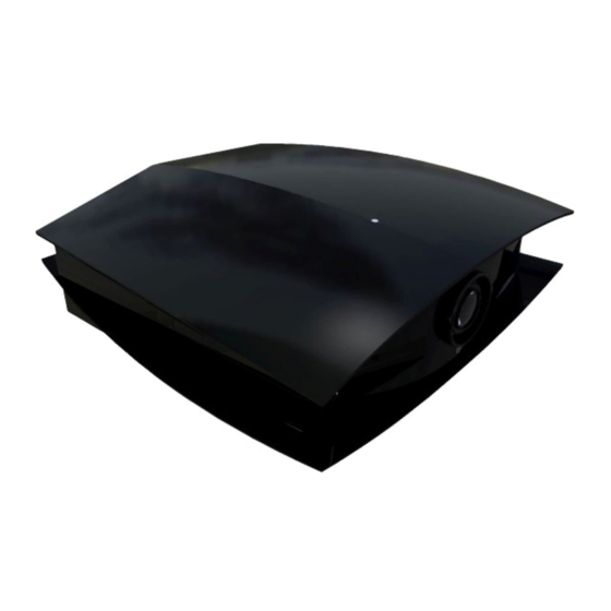
4.0 FEATURES AND CONNECTIONS 4.0 FEATURES AND CONNECTIONS 4.1 General View Front side b’ a) Lens Shift Cover Remove this cover when using the Lens Shift feature for shifting the projecting position in the vertical direction. Refer to “Vertical lens shift”, page 12 for details. b) and b’) Air inlets (2 in front and 1 at bottom surface) The air inlets absorb air to cool the interior of the unit. -
Page 15: Digital Control Panel
4.0 FEATURES AND CONNECTIONS When operating with the remote control, aim it towards the sensor. A remote sensor is also located at the front of the unit. d) AC Power Input Terminal This is the AC power input terminal. Connect the supplied cord to this terminal. e) [RS-232C] Terminal (D-sub 9 Pin) This is the RS-232C interface-specific terminal. -
Page 16: Indicators
4.0 FEATURES AND CONNECTIONS 4.3 Indicators Indicator Display on the rear side STAND BY OPERATE LAMP TEMP HIDE a) [STAND BY] Indicator Light on:When in the standby mode. Blinking:When in the cool down mode. b) [OPERATE] Indicator Light on:When this unit is currently operating (projecting). c) [LAMP] Button Light on: When the lamp needs to be replaced soon or immediately. -
Page 17: Indicator Display On The Digital Control Panel
4.0 FEATURES AND CONNECTIONS Indicator Description STAND OPERATE LAMP TEMP HIDE Light On Unit is in standby mode Light On Unit is in operate mode (during projection) When the video image is temporarily cleared Light On Light On upon pressing the [HIDE] button during projection Unit is in cool down mode Blinking... - Page 18 4.0 FEATURES AND CONNECTIONS a) Remote Control’s Signal Transmitter b) [OPERATE ON] Button When this unit is in the standby mode, pressing this button for OPERATE more than 1 second will turn the unit on and cause the [OPER- ATE] indicator to light up. TEST LIGHT c) [LIGHT] Button...
-
Page 19: Connections
4.0 FEATURES AND CONNECTIONS Battery insertion in the Remote Control 1. Push the cover tab with the fingernail a little backwards and pull upwards the cover top. Slide the cover forward to remove. 2. Push the battery body towards the spring and lift up to remove. -
Page 20: Automation And Control Port : Rs-232 Input
4.0 FEATURES AND CONNECTIONS DVI-D connector HDMI to DVI-D cable Connect the BlackWing to the Master Two with a HDMI to DVI-D Male cable. Make sure to use a good quality cable, especially when the distance between the different devices are longer than 5 meters. - Page 21 4.0 FEATURES AND CONNECTIONS AUTION GAINST IRE AND LECTRIC HOCK Since the power consumption of this unit is high, insert the power plug directly into a wall outlet. When not using devices, remove the power plug from the wall outlet. Do not use power cords for connection other than specified.
-
Page 22: Basic Operations Procedures
5.0 BASIC OPERATIONS PROCEDURES 5.0 BASIC OPERATIONS PROCEDURES 5.1 First Startup If setting for this unit is not completed, please refer to “ADJUSTMENTS AND SETTINGS”, page 24 upon turning on the power and perform the required setting accordingly. Once the basic setting is completed, this unit can be used by simply performing the following operation procedures. -
Page 23: Turning Off The Power
5.0 BASIC OPERATIONS PROCEDURES • Press the [HIDE] button again the restore the image. STAND BY light ON OPERATE LAMP TEMP light ON HIDE Turning off the power • Press the [OPERATE OFF] button for 1 second or more The [OPERATE] indicator turns off, the [STAND BY] indicator starts blinking and this unit switches to the cool down mode. -
Page 24: Adjustments And Settings
6.0 ADJUSTMENTS AND SETTINGS 6.0 ADJUSTMENTS AND SETTINGS The menus displayed on the screen are used to perform adjustment and setting for this unit. 6.1 How to start up the menus Box like menu structure The menu structure is built up with boxes which allow easy access to different parameters for setting up the projec- tor. -
Page 25: Menu Structure
Setting to Custom enables you to set (adjust) to a gamma value of your preference via the computer that is connected to the projector by using a Gamma adjustment software. (Default picture quality is equivalent to Normal). Ask your dealer for the Gamma adjustment software or contact us at www.cineversum.com. b) Color Temp. -
Page 26: Setup Menu
6.0 ADJUSTMENTS AND SETTINGS Adjusts the color temperature of the projected image. Setting Values: D65,User1,User2 Default Value: D65 c) Red,Green,Blue Setting Values: -255 to 0 Default Value: 0 When you set the Color Temp. setting to User1 or User2, adjustment of Red,Green,Blue can be done. d) Test Pattern Use this to adjust focus, screen size or picture quality. -
Page 27: Option Menu
6.0 ADJUSTMENTS AND SETTINGS Inverts image upside down. Setting Values: On,Off Default Value: Off e) Picture Shift When projecting images with black bands at the top and bottom (cinema image), use this to move the image up or down while retaining one of the black bands at the upper or lower end. Setting Values: -30 to 30 Default Value: 0 Option Menu... - Page 28 6.0 ADJUSTMENTS AND SETTINGS NPUT NFORMATION When the input video signal is switched, a blue back image will appear for about 2 seconds. When nothing is connected to the [DVI] terminal, or if there is no video signal, a No Signal DVI-D message will be projected.
-
Page 29: Advanced Settings
7.0 ADVANCED SETTINGS 7.0 ADVANCED SETTINGS 7.1 Picture Shift setting When projecting images with black bands at the top and bottom (cinema image), use this to move the image up or down while retaining one of the black bands at the upper or lower end. The default value is 0 (Off) and can be set from -30 to +30. -
Page 30: Input Balance
7.0 ADVANCED SETTINGS Project the picture on the screen. Normal Custom Gamma Image Adjust Color Temp. User1 User2 Setup Press the MENU button to get the main menu on the screen. Options Green Information Blue Test Pattern ENTER Pixel Adjust ENTER Menu Position Image Adjust... -
Page 31: Color Temperature Settings
7.0 ADVANCED SETTINGS 232C link. The gamma custom setting requires some experience. Color Temperature settings Color temperature can be selected to be D65, User1 or User2. (User1 and 2 allows a fine adjustment of the values for red, green, and blue). Color temperature stands for the spectral properties of a light source. -
Page 32: Maintenance
8.0 MAINTENANCE 8.0 MAINTENANCE 8.1 Clean dirt on the cabinet Always use a soft cloth. In case of heavy soiling, soak a cloth in neutral detergent diluted with water, wring dry and wipe, followed by wiping again using a dry cloth. CAUTION Pay attention to the following as the cabinet may deteriorate in condition, get damaged or paint may come off. -
Page 33: Procedure For Lamp Replacement
8.0 MAINTENANCE BOUT EPLACEMENT If this unit is installed in a constricted place, attempting to replace the lamp in that place may cause injury. Move this unit to a place large enough to perform work. Use only genuine replacement parts for the lamp unit. Otherwise, malfunction may occur. Also, never attempt to re- use an old lamp unit. -
Page 34: Reinstall The Inner Filter
8.0 MAINTENANCE Clean the filter with water and dry it, avoiding direct sunlight. In extremely soiled cases, use of a neutral detergent is recommended. Reinstall the inner filter Check that the 2 claws at the left and right of the inner filter are locked to this unit. R599727 - BlackWing User Manual... -
Page 35: Troubleshooting
8.0 MAINTENANCE 8.5 Troubleshooting Full Screen Warnings Message Cause (Details) No device is connected to the [DVI] terminal. The DVI-D cable is connected to the [DVI] terminal but there is no signal input. No Signal DVI-D Input the video signals. A video signal that cannot be used with this unit has been input. -
Page 36: Before Sending The Projector To Repair
8.0 MAINTENANCE If abnormality occurs in this unit during projection, the warning mode will be triggered and the type of abnormality will be indicated by a combination of indicators displayed on the top surface of this unit. This unit will then automatically stop projection and run the cooling fan for about 60 seconds. Indicator Warning STAND BY... - Page 37 8.0 MAINTENANCE Before sending the unit to repair, check the following points. Symptom Probable Cause Corrective Action Power is not Is the power cord disconnected? Insert the power cord (plug) properly. supplied Is the lamp cover properly shut? Remove the plug when the [STAND BY] indicator is on.
-
Page 38: Connection Details
9.0 CONNECTION DETAILS 9.0 CONNECTION DETAILS 9.1 RS-232C input Pin Assignment Pin No. Signal Name Pin No. Signal Name 9 8 7 6 5 4 3 2 1 External Control Control of this unit is possible via a computer by connecting this unit to an automation device or computer with a RS-232C cross cable (D-sub 9 pins). - Page 39 9.0 CONNECTION DETAILS Header : Designates the head of the data. @ (40h): Fetches data from the projector : 1: Identification number of the projector (Factory setting is 1) : Designates the delimiter for ID, Command and Parameter. (20h) Normal Termination : 0 (30h) Status : Designates the terminal of the data.
-
Page 40: Dvi-D Input
9.0 CONNECTION DETAILS 9.2 DVI-D input Pin Assignment Pin No. Signal Name Pin No. Signal Name TMDS data 2- TMDS data 2+ TMDS +5 V power supply TMDS data 2/4 shield Earth (+5 V) Hot plug detection TMDS data 0- DDC clock TMDS data 0+ DDC data... -
Page 41: Specifications
10.0 SPECIFICATIONS 10.0 SPECIFICATIONS 10.1 Overview The BlackWing uses the latest technology developed for professional projectors. The D-ILA is the abbreviation for Direct drive Image Light Amplifier. D-ILA devices are manufactured using extremely high-precision technology. Emission Method D-ILA (Reflective Active Matrix Principle) Display Panel/Size D-ILA Device / 0.82"... - Page 42 Contact Information: TEC - CineVERSUM 7, rue La CAILLE, 75017 Paris - FRANCE Phone: +33 1 42 29 44 44, Fax: +33 1 42 29 09 10 e-mail : info@cineversum.com, Web: www.cineversum.com R599727 - BlackWing User Manual...
Need help?
Do you have a question about the BlackWing R9010084 and is the answer not in the manual?
Questions and answers