
Related Manuals for Stewart Audio CVA 100-2


Summary of Contents for Stewart Audio CVA 100-2
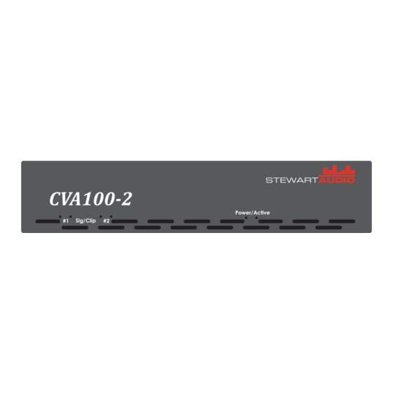
- Page 1 CVA100-2 Power/Active Sig/Clip Owner’s Manual CVA 100-2 October 2011 www.stewartaudio.com...
-
Page 2: Important Safety Instructions
Airflow around the unit should be unobstructed. Before using your Stewart Audio Inc. Power Amplifier, please read this Owner’s Manual carefully to ensure optimum trouble-free perfor- This amplifier should not be used near water, for example, near a bathtub, mance. -
Page 3: Table Of Contents
2.4 Input Connections ····························································· 8 1.1 Features 2.5 Output Connections ·························································· 10 Your Stewart Audio CVA 100-2 amplifier is the result of years of experi- 3 Operation ······················································································ 12 ence in the design and manufacture of quality amplifiers. As such it 3.1 Operation Precautions ·······················································... -
Page 4: Setup
2.2.3 Proper Cooling Considerations 2 Setup Cooling of the CVA 100-2 amplifier is achieved by Stewart’s unique 2.1 Setup Precautions whole chassis heatsink design, which utilizes the entire chassis as a heatsink to cool the heat generating components inside. In the event... -
Page 5: Input Connections
When using a balanced input source and connector, you must ensure that the hot, cold, and ground pins of the connector are matched up to the +, -, and ground pins of the CVA 100-2’s Euro Block connector re- spectively. Diagrams have been provided for standard XLR and TRS connectors. -
Page 6: Output Connections
2.5.1 Constant Voltage Wiring Example art Audio. These will allow for a quicker installation with less room for error when connecting the CVA 100-2 amplifier to an unbalanced The diagram below is a typical wiring setup for two speakers with out- source. -
Page 7: Operation
#1 Sig/Clip #2 #1 Input #2 NOTE: Stewart Audio will not be held responsible for damage to your CVA 100-2 amplifier or connected equip- CobraNet Input (Optional) Front Signal and Clip LEDs ment if the instructions in this manual are not followed. - Page 8 The green LEDs, labeled “Sig”, will light when an audio signal is pre- sent on the corresponding audio input channel. The red LEDs, labeled CVA 100-2 amplifiers can have their volume remotely controlled (or “Clip” will illuminate when the signal is too hot. The “Level” control muted) via the Euro Block input on the rear of the amplifier.
-
Page 9: Cobranet
A: Since the CVA100 is a 2-channel device, only the first two submap channels are valid (channels 1 and 2). Data sent on channels 3-8 will be The CVA 100-2 has an optional CobraNet card that allows it to receive ignored. -
Page 10: Troubleshooting
NOTE: If using CobraNet audio, do not plug anything into Problem: Amplifier overheats and/or shuts off. the physical input channels on the rear of the CVA 100-2 Procedure: Review section 2.2.3 on proper cooling procedures. Check the clip LEDs on the front or rear of the amplifier to see if the signal is When configured to use CobraNet Audio, the CVA 100-2 will continue overdriving (the signal light flashes red frequently). -
Page 11: Technical Specifications
6.2 Return Procedure Weight 2.8 lbs (1.27kG) Stewart Audio reserves the rate to change features and specifications without notice. This section includes the return procedures which must be followed in order to prevent processing delay or cost to the customer. Please read... -
Page 12: Return Authorization
2. Do not ship any accessories (manuals, cords, hardware, etc.) with your unit. These items are not needed to service your product. If Stewart Audio is unable to contact the sender in 14 days, the mer- Stewart Audio will not be held responsible for these items if they chandise will be considered scrap and may be disposed of. -
Page 13: Accessories
8 Notes 7 Accessories The following accessories are available from Stewart Audio for your amplifier. All part numbers shown are Stewart Audio Part Numbers. Rack Mounting Brackets RMK-70-S Hardware for racking a single amplifier centered in a 1U space RMK-70-D...
Need help?
Do you have a question about the CVA 100-2 and is the answer not in the manual?
Questions and answers