
Related Manuals for Cardio Theater xTV9T4


Summary of Contents for Cardio Theater xTV9T4
- Page 1 INSTRUCTION MANUAL xTV9T4 – 900 Mhz 4 Channel Transmitter xTV9R Receiver Cardio Theatre Holdings, Inc. 20031 142 Ave NE P.O. Box 7202 Woodinville, WA 98072-4002 (800) 776-6695 (425) 486-9292 www.cardiotheater.com P/NCXXTV9T4MAN-101...
-
Page 2: Table Of Contents
Retain this manual for future reference. For your records Record the serial number found on the back of the xTV9T4 Transmitter. Refer to the serial number whenever you call your dealer for information or service. Serial Number: Unpacking Unpack the units carefully and secure all parts so that none are misplaced. -
Page 3: Fcc Compliance Statement
FCC Compliance Statement NOTE: This equipment has been tested and found to comply with the limits for Part 15 of the FCC Rules. These limits are designed to provide reasonable protection against harmful interference when the equipment is operated in a commercial environment. This equipment generates, uses, and can radiate radio frequency energy and if not installed and used in accordance with the instruction manual, may cause harmful interference to radio communications. -
Page 4: Before You Begin
Before You Begin • Please ensure that you have all of the required equipment before disposing of any packing materials. xTV9T4 Transmitter XTV9R Receiver Wire Ties In the quantity ordered Quantity – two per receiver Kit008 Power Cord Power adaptor and Quantity –... -
Page 5: Important Safeguards
Important Safeguards Please read all of the safeguards before operating 7. Heat - The unit should be located away from heat this unit. Follow all warnings placed on the unit and sources such as radiators, heat registers, stoves, etc. adhere to the operating and use instructions. Retain this manual for future reference. -
Page 6: Safety Precautions
Important Safeguards - Continued 12. Stands - Any component stand should be moved 14. Damage requiring service – The unit should be with care. Quick or excessive force would cause the serviced by a qualified Cardio Theater technician stand to overturn when: A. -
Page 7: Suggestions For Installation
• Make sure the antenna is in the vertical position and within line of site to each receiver. • The range of the xTV9T4 transmitter is a line of sight (300-foot diameter) from the transmitter antenna. (I.e., if you’re within 150 ft. and can physically see the antenna, you should have good reception.) •... -
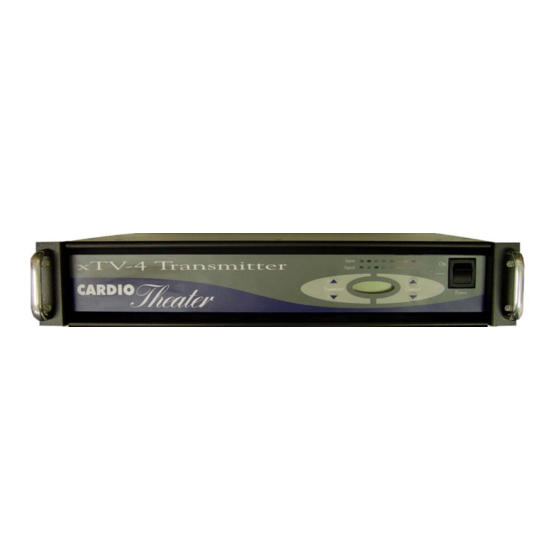
Page 8: Controls And Indicators
Controls and Indicators xTV9T4 Transmitter - Front 1. Transmitter Select – Used to select transmitter output, 1-4 (program mode only). 2. Input Signal – For viewing audio input levels. Power-on Indicator - Lights when main power switch is on. 4. On / Off Switch – Turns power on or off to transmitter 5. - Page 9 Controls and Indicators xTV9 Receiver 1. Channel Display - Indicates current channel selected. 2. Channel Select - To select the desired listening channel. 3. EQ Tone - Adjusts audio to predefined EQ settings 4. Volume Adjust - To select desired listening volume. 5.
-
Page 10: System Connections
Connect the antenna to the antenna connector on the back of the xTV9T4 transmitter. Step 2 Connect up to four (4) audio components to the stereo input jacks on the back of the xTV9T4 transmitter. Step 3 Use the power cord supplied to connect the transmitter to AC power. - Page 11 System Connections, Transmitter/TV Setup...
- Page 12 System Connections, Transmitter/Satellite Setup...
-
Page 13: Attaching Xtv Receivers
Attaching xTV Receivers The xTV Receiver can be attached to virtually any piece of equipment. • Attach the supplied coiled control cable into the RJ45 telephone connector on the back of the receiver, as shown below. Be careful to push the rubber boot firmly into the recess to form a tight seal around the connector. -
Page 14: Xtv9T4 Transmitter Setup
Transmitter Setup NORMAL OPERATION There are four modes that the transmitter can be in: xTV US/Canada 32 possible frequencies LCS US/Canada 52 possible frequencies xTV Australia 16 possible frequencies LCS Australia 24 possible frequencies Upon power up, the display will show '88.88' briefly as a lamp test, then display briefly one of the four shown below to... -
Page 15: Transmitter Frequency Chart
Transmitter Frequency Chart Cardio - United States Cardio - Australia xTV - United States xTV - Australia Frequency Channel Frequency Channel Frequency Channel Frequency Channel 905.4 916.2 905.0 923.6 907.4 917.4 906.2 924.4 909.0 918.0 923.6 925.6 910.4 919.4 924.4... -
Page 16: Receiver Programming
Programming the Receiver The procedure outlined below must be followed, to set up your receivers for first time use or anytime a receiver is replaced. Make sure that all transmitters that will used in the Club are on and operating before going through the programming procedures below. -
Page 17: Receiver Maintenance
Receiver Maintenance Replacing a worn Headphone Jack Assembly Remove receiver from the cardio equipment. On the back of the receiver remove the two inner screws on the bottom of the receiver as shown below. This will release the worn headphone jack assembly from the receiver. Turn receiver over, remove the worn headphone jack assembly and discard. -
Page 18: Specifications
Specifications xTV9T4 –Transmitter Transmission bandwidth....………..902 MHz to 928 MHz Frequency Range........…….. adjustable from 905.4 MHz to 926.2 MHz. Available Channels……………………….……..32 channels xTV mode, 52 Cardio LCS mode Transmission Power.........…….. 95 dbmv max. Transmission Range.........…….. 150 ft. from antenna Power Consumption.........…….. -
Page 19: Warranty
Limited Warranty PLEASE READ THESE WARRANTY TERMS AND CONDITIONS CAREFULLY BEFORE USING YOUR CARDIO THEATER PRODUCT. BY USING THE EQUIPMENT, YOU ARE CONSENTING TO BE BOUND BY THE FOLLOWING WARRANTY TERMS AND CONDITIONS. Limited Warranty. Disclaimer and Release. Precor Incorporated (“Precor”) warrants all new Cardio Theater products to be free from defects in The warranties provided herein are the exclusive materials and manufacture for the warranty periods set forth below. -
Page 20: Technical Support
Cardio Theater PVS and Cardio Theater Quick Change Headphone Jack are registered trademarks of Cardio Theatre Holdings, Inc. © 2004 Cardio Theatre Holdings, Inc., all rights reserved...
Need help?
Do you have a question about the xTV9T4 and is the answer not in the manual?
Questions and answers