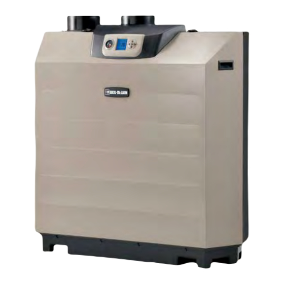
Weil-McLain Ultra Commercial Installation And Start-Up Manual

Weil-McLain Ultra Commercial Installation And Start-Up Manual

Commercial gas-fired water boiler
Hide thumbs Also See for Ultra Commercial:
Table of Contents

Advertisement

Gas-fired water boilers
Featuring
®
Flexibility
Boiler Manual
This manual must only be used by a qualified heating installer/service technician. Read all instructions, including this
manual and all other information shipped with the boiler, before installing. Perform steps in the order given. Failure to
comply could result in severe personal injury, death or substantial property damage.
Part number 550-100-086/0809

Advertisement

Table of Contents
loading

Summary of Contents for Weil-McLain Ultra Commercial

  • Page 1 Gas-fired water boilers Featuring ® Flexibility Boiler Manual This manual must only be used by a qualified heating installer/service technician. Read all instructions, including this manual and all other information shipped with the boiler, before installing. Perform steps in the order given. Failure to comply could result in severe personal injury, death or substantial property damage.
  • Page 2 — Boiler Manual COMMERCIAL GAS FIRED WATER BOILER COMMERCIAL gas-fired water boiler Featuring Flexibility Knockouts are provided in the jacket top panel, allowing con- duit entry directly behind the control panel or near the wall. Air enters the boiler enclosure through the air intake adapter (18), flows through the enclosure, enters the air inlet silencer (5), then enters the venturi (6).
  • Page 3 — Boiler Manual COMMERCIAL GAS FIRED WATER BOILER COMMERCIAL gas-fired water boiler Featuring Flexibility Part number 550-100-086/0809...
  • Page 4: Hazard Definitions

    — Boiler Manual COMMERCIAL GAS FIRED WATER BOILER Contents Hazard definitions The following defined terms are used throughout this manual to bring attention to the presence of hazards of various risk levels or to important information concerning the life of the product. Indicates presence of hazards that will cause severe personal injury, death or substantial property damage.
  • Page 5: Please Read Before Proceeding

    — Boiler Manual COMMERCIAL GAS FIRED WATER BOILER Please read before proceeding — Read all instructions, Failure to adhere to the guidelines on this page can result including this manual and all other in severe personal injury, death or substantial property information shipped with the boiler, damage.
  • Page 6: Prepare Boiler Location

    — Boiler Manual COMMERCIAL GAS FIRED WATER BOILER Prepare boiler location Installations must comply with: Clearances Local, state, provincial, and national codes, laws, regulations and ordinances. National Fuel Gas Code, ANSI Z223.1 – latest edition. Standard for Controls and Safety Devices for Automatically Fired Boilers, ANSI/ASME CSD-1, when required.
  • Page 7: Placing Multiple Boilers

    — Boiler Manual COMMERCIAL GAS FIRED WATER BOILER Prepare boiler location (continued) Placing multiple boilers Side-to-side mounting of multiple Ultra boilers Locate multiple boilers in boiler room to provide the clearances shown in: a. Figure 2 (side-to-side), or b. Figure 3 (back-to-back). Provide indicated clearances around boilers for ac- cess and servicing.
  • Page 8: Flooring And Foundation

    — Boiler Manual COMMERCIAL GAS FIRED WATER BOILER Prepare boiler location (continued) Flooring and foundation Provide air openings to room Air openings — General Flooring Follow the National Fuel Gas Code (U. S.) or CSA B149.1 and B149.2 (Canada) and all applicable codes to size/verify size of the combustion/ The Ultra boiler is approved for installation on ventilation air openings into the space.
  • Page 9: Prepare Boiler

    (when required) Ultra boilers are rated ANSI Z21.13 Category IV (pressurized vent, likely to condense in the vent). Ultra commercial boilers can be either (vent to the outside, combustion air from inside) or (vent and air piped outside).
  • Page 10 — Boiler Manual COMMERCIAL GAS FIRED WATER BOILER Prepare boiler (continued) Install propane orifice — Ultra-550 or -750 Legend for Figure 4, page 11 — You must turn off electrical (see Figure 93, page 104 for part numbers) supply to the boiler and close the external manual gas shut- off valve to isolate the boiler during conversion.
  • Page 11 — Boiler Manual COMMERCIAL GAS FIRED WATER BOILER Prepare boiler (continued) See opposite page for legend is used on all Ultra-550 boilers, for both natural gas and propane. is used on Ultra-750 propane, but NOT on natural gas. MUST be installed on both the Ultra-550 and Ultra-750 to operate on propane. Verify model number &...
  • Page 12: Perform Hydrostatic Pressure Test

    — Boiler Manual COMMERCIAL GAS FIRED WATER BOILER Prepare boiler (continued) Hydrostatic test piping connections . This is the maximum allowable relief valve setting for the Ultra boiler. The boiler is shipped with a 30 PSIG relief valve. See Replacement parts in the back of this manual for alternate pressure setting relief valves.
  • Page 13: Install Water Piping

    — Boiler Manual COMMERCIAL GAS FIRED WATER BOILER Install water piping Use two wrenches when tightening water piping at boiler, Backflow preventer using one of the wrenches to prevent the boiler interior piping from turning. Failure to support the boiler piping Use backflow check valve in cold water supply as re- connections to prevent them from turning could cause quired by local codes.
  • Page 14: System Water Piping Methods

    flow through the Ultra boiler, for the most efficient and reliable operation of the boiler and the heating system. For other piping methods, consult your local Weil-McLain representative or see separate Ultra boiler piping guides. Recommended pipe sizing Connect minimum 2”...
  • Page 15: Expansion Tank And Make-Up Water

    — Boiler Manual COMMERCIAL GAS FIRED WATER BOILER Install water piping (continued) Expansion tank and make-up water Expansion tank piping Ensure expansion tank size will handle boiler and system water volume and temperature. Allow 7 gallons per boiler for the boiler and its piping.
  • Page 16: Zoning With Zone Valves

    — Boiler Manual COMMERCIAL GAS FIRED WATER BOILER Install water piping (continued) Zoning with zone valves Zone valve zoning plus optional DHW piping Connect boiler to system as shown in Figure 8 when zone valve zoning. The primary/secondary piping shown ensures the boiler loop will have sufficient flow.
  • Page 17 — Boiler Manual COMMERCIAL GAS FIRED WATER BOILER Install water piping (continued) Zoning with zone valves — alternate Zone valve zoning plus optional DHW High-flow-rate/high-head-loss DHW circuits piping For applications requiring DHW circuit flow rates higher than al- lowable for the boiler, or for high pressure-drop coil-type DHW tanks, connect the piping as in Figure 9.
  • Page 18: Zoning With Circulators

    — Boiler Manual COMMERCIAL GAS FIRED WATER BOILER Install water piping (continued) Zoning with circulators Circulator zoning plus optional DHW piping Connect boiler to system as shown in Figure 10 when circulator zoning. The boiler circulator cannot be used for a zone. It must supply only the boiler loop.
  • Page 19 — Boiler Manual COMMERCIAL GAS FIRED WATER BOILER Install water piping (continued) Radiant heating applications Typical radiant heating system piping plus optional DHW The Ultra boiler is ideal for use in radiant heating. The Ultra boiler’s unique heat exchanger design allows it to work well even in condensing mode.
  • Page 20: Chilled Water Systems

    — Boiler Manual COMMERCIAL GAS FIRED WATER BOILER Install water piping (continued) Chilled water systems Chilled water system plus optional DHW piping Install boiler so that chilled medium is piped in parallel with the heating boiler. Use appropriate valves to prevent chilled medium from entering boiler.
  • Page 21: Multiple Boiler Water Piping

    Single-sided EZ-Fit Header connection or Figure 14. Size manifolds to handle total connected boiler output. Only 4-inch manifolds are available from Weil-McLain. All others must be field assembled. Provide connections in main header for Easy-Fit® manifolds as close as possible to the midpoint of multiple boilers.
  • Page 22 — Boiler Manual COMMERCIAL GAS FIRED WATER BOILER Multiple boiler water piping (continued) Piping schematic — typical piping for multiple Ultra boilers, using Weil-McLain Easy-Fit manifolds Legend — Figure 15 1 Flow/check valve (each boiler) 12 Isolation valve 13 Cold water supply 2 Isolation valves (when used) 16 Water flow switch (when used)
  • Page 23 COMMERCIAL GAS FIRED WATER BOILER Multiple boiler water piping (continued) Piping layout — typical piping for multiple Ultra boilers, using Weil-McLain Easy-Fit manifolds Use 2” or larger piping for all connections between boilers and manifolds Legend — Figure 16 1 Flow/check valve (each boiler)
  • Page 24 Legend — Figure 17 Flow/check valve (each boiler) Indirect-fired storage water heaters (Weil-McLain PLUS Line shown) — Example is shown with reverse-return boiler-side piping using a single circulator. Alternate: each water heater Isolation valves (when used) could have its own circulator.
  • Page 25 For pipe sizes larger than 3-inch, contact its own expansion tank as shown. 6b Heat exchanger shell-side circulator Weil-McLain for well-mounted sensors. Heating system circuit requires its own ex- 7 Expansion tanks (diaphragm type) 31 Install a union on the boiler supply and return connections...
  • Page 26: Venting/Combustion Air - General

    — Boiler Manual COMMERCIAL GAS FIRED WATER BOILER Venting/combustion air — general Combustion air contamination (combustion air from boiler room): Provide combustion air openings to boiler room as described in this manual. DO NOT COMMON VENT Ensure the boiler room and combustion air source areas are free of contaminants.
  • Page 27: Venting/Combustion Air - Options

    — Boiler Manual COMMERCIAL GAS FIRED WATER BOILER Venting/combustion air — options Vent and air piping materials Use only the materials listed below, ensuring that all materials meet local codes Figure 20 for approved vent and air piping ma- terials, for both —...
  • Page 28: Appliances Remaining On An Existing Vent System

    — Boiler Manual COMMERCIAL GAS FIRED WATER BOILER Appliances remaining on an existing vent system Existing vent test procedure Do not install the Ultra boiler into a com- (The following is intended to test whether the mon vent with any other appliance. This appliances remaining on an existing vent system will cause flue gas spillage or appliance will operate satisfactorily.)
  • Page 29: Commonwealth Of Massachusetts

    — Boiler Manual COMMERCIAL GAS FIRED WATER BOILER Venting/air piping — Massachusetts installations Venting instructions for the installations in the Commonwealth of Massachusetts (a) For all sidewall horizontally-vented gas-fueled equipment . The state or local gas inspector of the side wall horizontally vented gas fueled equipment shall installed in every dwelling, building or structure used in not approve the installation unless, upon inspection, whole or in part for residential purposes, including those...
  • Page 30: Direct Exhaust - Boiler Room Air Openings

    DIRECT EXHAUST — Boiler room air openings Combustion air provision Special considerations The Ultra Commercial boiler can use inside air if no contaminants are Tight construction present in the boiler space. (If contaminants are likely to be present, install ANSI Z223.1 defines unusually tight construction...
  • Page 31: Air Openings

    — Boiler Manual COMMERCIAL GAS FIRED WATER BOILER DIRECT EXHAUST — Boiler room air openings (continued) MINIMUM combustion air openings for direct exhaust applications — Air openings Ultra boiler Ultra boiler The required air opening sizes below are FREE AREA, WITH other WITHOUT other after reduction for louver obstruction.
  • Page 32: Direct Exhaust - Sidewall

    — Boiler Manual COMMERCIAL GAS FIRED WATER BOILER DIRECT EXHAUST — Sidewall Allowable vent pipe materials Use only the materials listed in Figure 20, page 27. Install a bird screen in each vent pipe termination (coupling or elbow). Bird screens are supplied with the boiler. Cut to size if necessary to fit vent pipe size used.
  • Page 33 — Boiler Manual COMMERCIAL GAS FIRED WATER BOILER DIRECT EXHAUST — Sidewall (continued) Apply the configuration on the right side of Figure 24 when DIRECT EXHAUST — Sidewall — the termination needs to be raised higher to meet clearance to clearances to openings grade or snow line.
  • Page 34 — Boiler Manual COMMERCIAL GAS FIRED WATER BOILER DIRECT EXHAUST — Sidewall (continued) Maintain clearances as shown in the illustrations in this manual DIRECT EXHAUST — Sidewall — section. Also maintain the following: termination assembly — all parts by Vent must terminate: installer At least 6 feet from adjacent walls.
  • Page 35: Direct Exhaust - Vertical

    — Boiler Manual COMMERCIAL GAS FIRED WATER BOILER DIRECT EXHAUST — Vertical Allowable vent pipe materials DIRECT EXHAUST vertical termination Use only the materials listed in Figure 20, page 27. Install a bird screen in each vent termination (coupling or elbow). Bird screens are supplied with the boiler.
  • Page 36 — Boiler Manual COMMERCIAL GAS FIRED WATER BOILER DIRECT EXHAUST — Vertical (continued) near adjacent buildings or surfaces, window wells, stairwells, DIRECT EXHAUST — Vertical termination alcoves, courtyards or other recessed areas. Locate or guard vent to prevent condensate damage to exterior finishes.
  • Page 37: Direct Vent - Boiler Room Air Openings

    — Boiler Manual COMMERCIAL GAS FIRED WATER BOILER DIRECT VENT — Boiler room air openings Combustion/ventilation air provision but also to handle the air movement rate of the ex- haust fans or air movers using air from the building For direct vent installations, combustion air must be ducted directly from or space.
  • Page 38 — Boiler Manual COMMERCIAL GAS FIRED WATER BOILER DIRECT VENT — Boiler room air openings (continued) MINIMUM combustion air openings for direct vent applications — Air openings Ultra boiler Ultra boiler The required air opening sizes below are FREE AREA, WITH other WITHOUT other after reduction for louver obstruction.
  • Page 39: Direct Vent - Sidewall

    — Boiler Manual COMMERCIAL GAS FIRED WATER BOILER DIRECT VENT — Sidewall Allowable vent/air pipe materials Use only the materials listed in Figure 20, page 27. Install a bird screen in each vent and air pipe termination. Bird screens are supplied with the boiler. Cut to size if necessary to fit vent pipe size used.
  • Page 40 — Boiler Manual COMMERCIAL GAS FIRED WATER BOILER DIRECT VENT — Sidewall (continued) Apply the configuration on the right side of Figure 35 when Sidewall termination with separate pipes the terminations need to be raised higher to meet clearance to —...
  • Page 41 — Boiler Manual COMMERCIAL GAS FIRED WATER BOILER DIRECT VENT — Sidewall (continued) Prevailing winds could cause freezing of condensate and water/ Multiple terminations — separate pipes — ice buildup where flue products impinge on building surfaces clearance from vent of one to air intake of or plants.
  • Page 42 — Boiler Manual COMMERCIAL GAS FIRED WATER BOILER DIRECT VENT — Sidewall (continued) The air inlet of an Ultra boiler is part of a direct vent connection. DIRECT VENT — Sidewall — termination It is not classified as a forced air intake with regard to spacing from assembly (all parts by installer, except the adjacent boiler vents.
  • Page 43: Direct Vent - Vertical

    — Boiler Manual COMMERCIAL GAS FIRED WATER BOILER DIRECT VENT — Vertical Allowable vent/air pipe materials Use only the materials listed in Figure 20, page 27. Install a bird screen in each vent and air pipe termination. Bird screens are supplied with the boiler. Cut to size if necessary to fit vent pipe size used.
  • Page 44 — Boiler Manual COMMERCIAL GAS FIRED WATER BOILER DIRECT VENT — Vertical (continued) Consider the surroundings when terminating the vent and air: Vertical termination — separate pipes Position the vent termination where vapors will not damage nearby shrubs, plants or air conditioning equipment or be objectionable.
  • Page 45 — Boiler Manual COMMERCIAL GAS FIRED WATER BOILER DIRECT VENT — Vertical (continued) Termination and fittings Termination location — separate pipes — terminations for multiple boilers Prepare the vent termination coupling and the air termination return bend (Figure 43, page 44) by inserting a bird screen in each. Bird screens are supplied with the boiler.
  • Page 46 — Boiler Manual COMMERCIAL GAS FIRED WATER BOILER Install vent/air piping — from termination to boiler Complete termination preparation Boiler vent and air connections Install vent and air terminations before proceeding. See previous pages for instructions. Installing vent and air piping For reference in the following see: DIRECT EXHAUST —...
  • Page 47: Install Condensate Components

    — Boiler Manual COMMERCIAL GAS FIRED WATER BOILER Install condensate components Install condensate drain tee Condensate drain tee assembly Figure 46. Remove PVC fittings and gasket from the acces- sories bag. Deburr and chamfer outside and inside of 1” PVC nipple (item 1) to ensure even cement distribution when joining.
  • Page 48 Condensate from the Ultra boiler will be slightly acidic (typically with a pH from 3.2 to 4.5). Install a neutralizing filter if required by local codes. See Replacement parts section at the end of this manual for the Weil-McLain kit. Condensate pump capacity, GPH For a condensate pump equipped with an overflow switch, the switch can be connected...
  • Page 49: Connecting Gas Supply Piping

    — Boiler Manual COMMERCIAL GAS FIRED WATER BOILER Gas piping Connecting gas supply piping Remove jacket front panel. See Figure 51 to connect gas supply , using one wrench pipe to the boiler. to prevent the boiler gas line connection Install a union for servicing, when required.
  • Page 50: Propane Gas

    High gas pressure: 14 inches w.c. Gas pressure switches Low gas pressure: 2 inches w.c. Ultra Commercial boilers are equipped with Note that the low gas pressure switch must be manually reset (button manual reset high gas pressure and low gas pressure on front of switch) on initial start-up or any time the gas supply is switches (see items 31 and 32, page 3).
  • Page 51: Field Wiring

    — Boiler Manual COMMERCIAL GAS FIRED WATER BOILER Field wiring — For your safety, turn off electrical power supply at service The U-Control allows the boiler to act as the primary entrance panel before making any electrical connec- or secondary heat source when another heat source, tions to avoid possible electric shock hazard.
  • Page 52 — Boiler Manual COMMERCIAL GAS FIRED WATER BOILER Field wiring (continued) Schematic wiring diagram — Ultra-550 & Ultra-750 (continued on next page) Part number 550-100-086/0809...
  • Page 53 — Boiler Manual COMMERCIAL GAS FIRED WATER BOILER Field wiring (continued) (continued from previous page) Schematic wiring diagram — Ultra-550 & Ultra-750 Part number 550-100-086/0809...
  • Page 54 — Boiler Manual COMMERCIAL GAS FIRED WATER BOILER Field wiring (continued) Ladder wiring diagram — Ultra-550 & Ultra-750 (continued on next page) Part number 550-100-086/0809...
  • Page 55 — Boiler Manual COMMERCIAL GAS FIRED WATER BOILER Field wiring (continued) (continued from previous page) Ladder wiring diagram — Ultra-550 & Ultra-750 Part number 550-100-086/0809...
  • Page 56: Low Water Cutoff

    Low water cutoff Ultra Commercial boilers are equipped with a low water cutoff, mounted on the boiler supply header. See item 21, page 3. You can connect any of the circulators you use to any of the The low water cutoff is wired to the U-Control and requires three circulator activation terminals.
  • Page 57: Outdoor Temperature Sensor

    — Boiler Manual COMMERCIAL GAS FIRED WATER BOILER Field wiring (continued) Additional limits Multiple boiler wiring options The U-Control can be programmed to sequence multiple The U-Control allows connection of external limit controls, boilers or operate/modulate in tandem from a 0–10 VDC both for manual reset and for automatic reset operation of source generated by the lead boiler or from a remote con- the U-Control.
  • Page 58: U-Control Operation And Setup

    — Boiler Manual COMMERCIAL GAS FIRED WATER BOILER U-Control operation and setup U-Control sequence of operation — You must ensure that the U- Control is set for the proper water temperatures for the (also see Figure 61, page 59) system. Excessive water temperature can cause significant Check the boiler model listed on the power-up property damage in some applications.
  • Page 59 — Boiler Manual COMMERCIAL GAS FIRED WATER BOILER U-Control operation and setup (continued) U-Control display and navigation Part number 550-100-086/0809...
  • Page 60 — Boiler Manual COMMERCIAL GAS FIRED WATER BOILER U-Control operation and setup (continued) EXPRESS SETUP — Using default settings ADVANCED SETUP – OVERVIEW The U-Control is factory programmed to supply a DHW circuit (control priority 1) and finned tube baseboard space heating (control priority 2).
  • Page 61 — Boiler Manual COMMERCIAL GAS FIRED WATER BOILER U-Control operation and setup (continued) When the boiler receives a 0–10 VDC input on ter- minals P15 #5 and #6, it starts up and modulates This setting is for multiple boilers or multiple heating sources (an firing rate according to the signal.
  • Page 62: Advanced Setup

    — Boiler Manual COMMERCIAL GAS FIRED WATER BOILER U-Control operation and setup (continued) U-Control system types and preset parameters 8-character 3-char Max Target Outdoor Temp Min Target Outdoor Temp Temp for Max Target Temp for Min Target Fan-coil FAN-COIL Finned tube baseboard FIN BASE Cast iron baseboard IRN BASE...
  • Page 63 — Boiler Manual COMMERCIAL GAS FIRED WATER BOILER U-Control operation and setup (continued) U-Control menus (press and hold the UP and DOWN arrow keys for 5 seconds to enter contractor menus) Follow information at the bottom of each screen to navigate to next/previous screen or enter/save data BOILER SETTINGS BOILER MODEL ##### HIGH ALTITUDE ###...
  • Page 64 — Boiler Manual COMMERCIAL GAS FIRED WATER BOILER U-Control operation and setup (continued) U-Control menus, continued (press and hold the UP and DOWN arrow keys for 5 seconds to enter contractor menus) Follow information at the bottom of each screen to navigate to next/previous screen or enter/save data DIAGNOSTICS INPUTS STATUS:...
  • Page 65 — Boiler Manual COMMERCIAL GAS FIRED WATER BOILER U-Control operation and setup (continued) U-Control setup options (see Figure 65, page 63 for location in menu sequence) Boiler Model 80, 105, 155, factory . Adjusts blower speeds 230, 299, 310, and flame sense (Display will show “HA” after the model number if high altitude has been 399, 550, 750 selected, below.) NOTE: Ultra-80 through Ultra-399 are residential models.
  • Page 66 — Boiler Manual COMMERCIAL GAS FIRED WATER BOILER U-Control operation and setup (continued) U-Control setup options (see Figure 65, page 63 for location in menu sequence), continued Max On Time minutes Longest time boiler will satisfy this system before switching to an active lower priority Min On Time minutes Time boiler will satisfy this system before switching to the next active priority...
  • Page 67 — Boiler Manual COMMERCIAL GAS FIRED WATER BOILER U-Control operation and setup (continued) U-Control diagnostic information (see Figure 65, page 63 for location in menu sequence Status Text data Current operating status of the boiler. Prepurge, Ignition, Name of the system Type being satisfied, post purge, Warm Weather Shutdown, Trouble System Supply °F...
  • Page 68 — Boiler Manual COMMERCIAL GAS FIRED WATER BOILER U-Control operation and setup (continued) U-Control diagnostic information (see Figure 65, page 63 for location in menu sequence), continued Alarm on-off data Control’s alarm contact status Analog Output data Value of 0–10 VDC output signal on P16 #1 and #2 Control Fault Displays number of control faults Ignition Retries...
  • Page 69 — Boiler Manual COMMERCIAL GAS FIRED WATER BOILER U-Control operation and setup (continued) U-Control diagnostic information (see Figure 65, page 63 for location in menu sequence), continued Status text data Current operating status of the boiler. Prepurge, Ignition, Name of the system Type being satisfied, post purge, Warm Weather Shutdown, Trouble Target °F...
  • Page 70: Startup - Fill The System

    Clean system to remove sediment Antifreeze You must thoroughly flush the system (without boiler Use only antifreeze listed by Weil-McLain as suitable for use connected) to remove sediment. The high-efficiency heat with Ultra Gas Boilers. A list of approved antifreeze products exchanger can be damaged by buildup or corrosion due to is available at www.Weil-McLain.com.
  • Page 71 fluids recommended If purge valves are not installed in system, open manual air vents in by Weil-McLain for application in Ultra system one at a time, beginning with lowest floor. Close vent when Boiler systems.
  • Page 72: Startup - Final Checks

    — Boiler Manual COMMERCIAL GAS FIRED WATER BOILER Startup — final checks Pour fresh water into the flue inspection opening until Check for gas leaks the condensate trap is full of water (water begins to flow out through condensate drain tee). Before starting the boiler, and during initial opera- Replace the flue inspection plug.
  • Page 73: Check System And Boiler

    Find the leak source with bubble test and problem, then shut down the boiler and repair immediately. Do not start boiler again until cor- contact your local Weil-McLain represen- rected. Failure to comply could result in severe personal tative. Throttle screw adjustment must injury, death or substantial property damage.
  • Page 74: Gas Valve Adjustment Procedure

    . Re-install the cover screw when completed. (see Figure 74, page 82) is reached, take a CO reading. Consult your local Weil-McLain representative if ac- Figure 69 to adjust if necessary. ceptable results cannot be obtained for both high and Remove the blue cover on the throttle screw opening with a low fire.
  • Page 75 — Boiler Manual COMMERCIAL GAS FIRED WATER BOILER U-Control operation and setup (continued) Operating instructions (WARNING — Verify that the U-Control is set for the correct boiler model before proceeding Part number 550-100-086/0809...
  • Page 76: Check-Out/Startup Verification

    — Boiler Manual COMMERCIAL GAS FIRED WATER BOILER Check-out/startup verification Gas valve leakage testing Fill out start-up data on the Installation and Service Certificate, page 112. DO NOT connect a manometer to the manual gas valve or the automatic gas valve. The high vacuum from the blower could pull fluid into the gas line, possibly damaging the gas valves.
  • Page 77: Annual Startup And General Maintenance

    — Boiler Manual COMMERCIAL GAS FIRED WATER BOILER Annual startup and general maintenance Service and maintenance schedules Service technician Owner maintenance (see following pages for instructions) (see Ultra User’s Information Manual for instructions) General: Reported problems. Check boiler area. Inspect interior; clean and vacuum if Check air openings.
  • Page 78: Annual Startup

    — Boiler Manual COMMERCIAL GAS FIRED WATER BOILER Annual startup HANDLING CERAMIC FIBER FIRST-YEAR SPECIAL INSPECTION MATERIALS after the boiler is in- REMOVAL OF SIGHT GLASS GASKET stalled, perform a first-year inspection of the boiler. This must include the following The sight glass gasket in this product contains ceramic fiber material.
  • Page 79: Address Reported Problems

    — Boiler Manual COMMERCIAL GAS FIRED WATER BOILER Annual startup (continued) Clean condensate trap The boiler should be inspected and Remove flue inspection plug (item 46, page 3). started annually, at the beginning of Inspect base collector with flash light. Flush out with water the heating season, only by a qualified as needed.
  • Page 80: Check Expansion Tank

    — Boiler Manual COMMERCIAL GAS FIRED WATER BOILER Annual startup (continued) Check the cold fill pressure for the system. Verify it is correct (usually Inspect ignition electrode around 12 psig). Remove the ignition electrode from the boiler heat Watch the system pressure as the boiler heats up (during testing) to exchanger.
  • Page 81: Check Burner Flame

    — Boiler Manual COMMERCIAL GAS FIRED WATER BOILER Annual startup (continued) Check burner flame (See Figure 75) Burner access The boiler contains ceramic fiber materials. Use care when handling these materials per instructions on page 78 of this manual. Failure to comply could Observation result in severe personal injury.
  • Page 82: Check Boiler Relief Valve

    — Boiler Manual COMMERCIAL GAS FIRED WATER BOILER Annual startup (continued) A lower flame signal may indicate a fouled ignitor or damaged ignitor Check boiler relief valve insulation. If cleaning the ignitor does not improve, ground wiring is in good condition, and ground continuity is satisfactory, replace the Inspect the relief valve and lift the lever to verify ignitor.
  • Page 83: Troubleshooting

    — Boiler Manual COMMERCIAL GAS FIRED WATER BOILER Troubleshooting VERIFY PROPER OPERATION AFTER SERVICING. VERIFY PROPER OPERATION AFTER SERVICING. VERIFY PROPER OPERATION AFTER SERVICING. Reinstall boiler jacket front door Before servicing and making connections . . . Reinstall boiler jacket front door after servicing.
  • Page 84: Check The Following

    — Boiler Manual COMMERCIAL GAS FIRED WATER BOILER Troubleshooting (continued) Check the following: Line voltage circuit fuse is 12-amp slow-blow (Littelfuse 257003). Make sure thermostat is calling for heat and con- Do not jumper fuse or replace with any tacts (including appropriate zone controls) are fuse except as specified.
  • Page 85 — Boiler Manual COMMERCIAL GAS FIRED WATER BOILER Troubleshooting (continued) Make sure to determine the causes of outages. Do not leave the boiler operating without a complete diagnosis. U-Control fault indications The U-Control provides diagnostic information for below the display illustration lists manual reset conditions and how both automatic reset conditions and manual reset to reset from them.
  • Page 86 — Boiler Manual COMMERCIAL GAS FIRED WATER BOILER Troubleshooting (continued) Troubleshooting suggestions for Ultra boilers U-Control Error Condition Log The U-control is able to record information about the boiler’s condition at the time of the three previous faults or errors. This information is available to view in Contractor Menus under “DIAGNOSTICS”...
  • Page 87 — Boiler Manual COMMERCIAL GAS FIRED WATER BOILER Troubleshooting (continued) Troubleshooting suggestions for Ultra boilers (continued) Condition Diagnostics Corrective Action(s) Display Nothing Control is not receiving 120V Check service switch and/or Turn on service switch to power boiler. is shown power circuit breaker to boiler turned in display...
  • Page 88 Manual reset is required if the Inspect vent system for abnormal wear or damage. temperature rises above 225°F. Reset using manual reset screen Contact Weil-McLain Technical Support. on display Occurs when dual Automatically resets when Follow procedure for above for SHORT and OPEN sensor conditions temperature sensors values sensors are within 10ºF.
  • Page 89 — Boiler Manual COMMERCIAL GAS FIRED WATER BOILER Troubleshooting (continued) Troubleshooting suggestions for Ultra boilers (continued) Condition Diagnostics Corrective Action(s) Display LIMIT OPEN Occurs when manual or Automatic external limit will Is there an external safety device connected? If yes, trouble shoot the automatic reset limit opens.
  • Page 90 — Boiler Manual COMMERCIAL GAS FIRED WATER BOILER Troubleshooting (continued) Troubleshooting suggestions for Ultra boilers (continued) Condition Diagnostics Corrective Action(s) Display GAS PRESSURE Gas pressure switch is open Either the low gas pressure Check gas pressure at tee mounted behind gas pressure switches during SW FAULT (high or low) switch or high gas pressure...
  • Page 91 — Boiler Manual COMMERCIAL GAS FIRED WATER BOILER Troubleshooting (continued) Troubleshooting suggestions for Ultra boilers (continued) Condition Diagnostics Corrective Action(s) Display GAS VALVE The U-Control has detected Reset using manual reset screen Check wire harness connections between gas valve and U-Control. FAULT a problem with its gas valve on display...
  • Page 92 — Boiler Manual COMMERCIAL GAS FIRED WATER BOILER Contact: Name: Contractor: Phone: Job name: Model: City, state: CP#: Distributor: Installed: Please note the placement of system sensors Near boiler pipe size: Boiler circulator model: DHW tank (yes/no): DHW direct/system: Dhw model: Dhw pipe size: DHW circulator model: Is there air in system?:...
  • Page 93: General Maintenance

    — Boiler Manual COMMERCIAL GAS FIRED WATER BOILER Maintenance Cleaning the heat exchanger — pin Disconnect power side when required Electrical shock hazard — Disconnect all electrical Shut down boiler: power to the boiler before attempting maintenance Follow “To Turn Off Gas to Appliance” instructions procedures.
  • Page 94 — Boiler Manual COMMERCIAL GAS FIRED WATER BOILER Maintenance (continued) Accessing & cleaning the heat If the silicone cord gasket has been damaged or stretched, exchanger replace it before placing the boiler back in operation. To install the silicone cord gasket: Remove heat exchanger cover plate and burner When installing the silicone cord gasket, the seam...
  • Page 95 — Boiler Manual COMMERCIAL GAS FIRED WATER BOILER Maintenance (continued) Removing heat exchanger cover plate Silicone cord starts and finishes at the top center Gasket Cleaning heat exchanger with cleaning tool 45° Down Horizontal 45° Up Part number 550-100-086/0809...
  • Page 96: Replacement Parts

    Results from using modified or other manufactured parts will not be covered by warranty and may damage boiler or impair operation. Weil-McLain part numbers are found in Weil-McLain Boilers and Controls Repair Parts Lists. . Use care when handling these materials per instructions on page 78 of this manual.
  • Page 97 — Boiler Manual COMMERCIAL GAS FIRED WATER BOILER Replacement parts (continued) Miscellaneous parts and kits Part Number for Item Description Ultra 550/750 Condensate neutralizer kit (up to 1000 MBH) 383-600-076 591-706-200 Heat exchanger cleaning tool Pressure relief valve ASME 30 PSI, 3/4” NPT female 383-600-063 ASME 50 PSI, 3/4”...
  • Page 98 — Boiler Manual COMMERCIAL GAS FIRED WATER BOILER Replacement parts (continued) Jacket parts Part Number for Item Description Ultra 550/750 Jacket front door 383-600-052 Door seal 383-600-022 Handle (2 required) 383-500-611 Back Jacket 383-600-050 Jacket seal kit (base seal, door seal, grommets and gaskets) 383-600-053 Plastic top cover (includes cover, gaskets and hardware) 383-600-054...
  • Page 99 — Boiler Manual COMMERCIAL GAS FIRED WATER BOILER Replacement parts (continued) Jacket parts Part number 550-100-086/0809...
  • Page 100 — Boiler Manual COMMERCIAL GAS FIRED WATER BOILER Replacement parts (continued) Heat exchanger Boiler Item Description Part Number Models 5 section heat exchanger assembly kit (includes sections, o-rings, sealing cord 383-600-029 & hardware) 6 section heat exchanger assembly kit (includes sections, o-rings, sealing cord 383-600-028 &...
  • Page 101 — Boiler Manual COMMERCIAL GAS FIRED WATER BOILER Replacement parts (continued) Heat exchanger Part number 550-100-086/0809...
  • Page 102 — Boiler Manual COMMERCIAL GAS FIRED WATER BOILER Replacement parts (continued) Piping Boiler Item Description Part Number Models Supply manifold kit (Includes items 5 through 8 and 10 through 14) 550 / 750 383-600-055 Return pipe kit (includes items 9 and 14) 550 / 750 383-600-035 Inlet gas pipe kit (includes items 16, 17, and 18)
  • Page 103 — Boiler Manual COMMERCIAL GAS FIRED WATER BOILER Replacement parts (continued) Piping Part number 550-100-086/0809...
  • Page 104 — Boiler Manual COMMERCIAL GAS FIRED WATER BOILER Replacement parts (continued) Burner, blower, venturi and gas train Part Number for Item Description Ultra 550/750 5 section burner replacement kit (includes burner, gasket and nuts) 383-600-044 6 section burner replacement kit (includes burner, gasket and nuts) 383-600-043 Blower assembly kit (includes blower, gasket, o-ring and hardware) 383-600-045...
  • Page 105 — Boiler Manual COMMERCIAL GAS FIRED WATER BOILER Replacement parts (continued) Burner, blower, venturi and gas train Part number 550-100-086/0809...
  • Page 106 — Boiler Manual COMMERCIAL GAS FIRED WATER BOILER Replacement parts (continued) Controls Part Number for Item Description Ultra 550/750 3-amp, fast-blow ATO (5 fuses) 383-500-603 12-amp, slow-blow AG (5 fuses) 383 500 604 CSD1 U-control module 383-600-062 NON-CSD1 U-control module 383-500-658 Expansion module 383-600-060...
  • Page 107 — Boiler Manual COMMERCIAL GAS FIRED WATER BOILER Replacement parts (continued) Controls Part number 550-100-086/0809...
  • Page 108 — Boiler Manual COMMERCIAL GAS FIRED WATER BOILER Dimensions Dimensional data Notes Boiler supply and return connections are both 2” NPT. Circulator must be mounted in the return piping. Relief valve is shipped loose. See page 13 for mounting details. Relief valve mounts on supply pipe off of supply tee as shown. Boiler gas connection, 1¼”...
  • Page 109: Ratings - Ultra Boilers

    — Boiler Manual COMMERCIAL GAS FIRED WATER BOILER Ratings — Ultra boilers Ratings and engineering data Boiler Boiler Combustion Thermal Vent/Air Model Input Gross I=B=R Water Efficiency Efficiency Pipe Size Number Output Ratings Content (inches) Btuh Btuh Btuh Gallons (Note 2) (Note 5) (Note 5) (Note 1)
  • Page 110: Ratings - Multiple Ultra Boilers

    — Boiler Manual COMMERCIAL GAS FIRED WATER BOILER Ratings — multiple Ultra boilers Ratings and engineering data (see Figure 101 for notes) Manifolded Foundation size Total combustion Boiler Net water Side-to-side Back-to-back Heating air duct Boilers in system H.P. ratings arrangement arrangement input...
  • Page 111 Based on standard test procedures outlined by DOE for individual boilers, BTS-2000. Net I=B=R ratings are based on piping and pickup allowance of 1.15. Consult Weil-McLain Technical Services for other allowances. Foundation sizes in Figure 99 provide 12 inches between boilers and approximately 2 inches from boiler to edge of foundation.
  • Page 112: Installation And Service Certificate

    — Boiler Manual — Boiler Manual — Boiler Manual FIRED WATER BOILER FIRED WATER BOILER FIRED WATER BOILER Installation and Service Certificate Boiler Model Series CP Number Date Installed BTU Input Installation instructions have been followed. Check-out sequence has been performed. Above information is certified to be correct.

This manual is also suitable for:

Ultra-550Ultra-750

Table of Contents