
Related Manuals for LevelOne FCS-1081


Summary of Contents for LevelOne FCS-1081
-
Page 1: User Manual
LevelOne FCS-1081 / FCS-1081A PoE IP Camera User Manual Ver:2.3.0-0812 Copyright (c) 2008 Digital Data Communications Co., Ltd. All Rights Reserved. - Page 2 Before You Use This Product The use of surveillance devices may be prohibited by law in your country. The Network Camera is not only a high-performance web-ready camera but also can be part of a flexible surveillance system. It is the user’s responsibility to ensure that the operation of such devices is legal before installing this unit for its intended use.
- Page 3 ATTENTION All operation please refer to the instruction. Please don’t place the product on unstable desk or bracket. Please avoid any liquid permeate inside of the machine in case damage the product. Before wiring, please follow all electronic safety standards, and using the recommendable power supply adapter.
-
Page 4: Table Of Contents
Table of Contents Before You Use This Product ................2 Package Contents....................2 Hardware Installation ..................2 Software Installation..................4 Install “IP CamLocator” ................... 4 Install “IP CamSecure” ..................5 How to Use IP CamLocator................7 Initial use IP Cam Locator ................7 Configuration of Main Console................ 7 How to Access to the Network Camera............30 Initial accessing the network camera .............30 Setting......................34... -
Page 5: Before You Use This Product
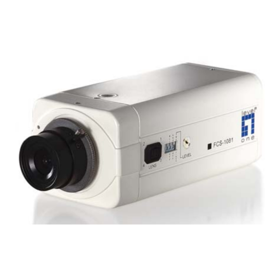
This will reduce the risk of accidental electric shock. Since FCS-1081/FCS-1081A is a PoE IP camera, it could work without attaching to power outlet as long as it connects to PoE switch. The Network Camera will first detect Ethernet. Until the Network Camera is connected to Network, the LED will become green and flash. - Page 6 To adjust the camera setting Consult with the dealer of the peripherals for correct installation. The Network Camera provides the auto iris lens connector. If the auto iris lens is used, the dip should be adjusted to AI option. And you also have to select VIDEO drive or DC drive lens by select correct iris mode.
-
Page 7: Software Installation
Software Installation In this manual, "User" refers to whoever has access to the Network Camera, and "Administrator" refers to the person who can configure the Network Camera and grant user access to the camera. At the end of the hardware installation, the Administrator must place the product software CD into the CD-ROM drive of the PC running in MS Windows. -
Page 8: Install "Ip Camsecure
Upon IP CamLocator’s start up, this program searches for LevelOne’s products on the same LAN. After searching, LevelOne Video Servers or Network cameras will be located by the IP CamLocator. There may be several entries shown in the window. The Administrator may differentiate the Network cameras with the model number and MAC address. - Page 9 Custom Setup Type: You may install the system to the directory of your preference and choose which feature(s) you want to install to the PC. Hint: You may, for instance, install only Playback and/or LiveView on the PC at home or other remote site from which you do not install the camera but are going to watch them remotely.
-
Page 10: How To Use Ip Camlocator
How to Use IP CamLocator This chapter introduces how to monitor the image from the camera using IP CamLocator. The LevelOne video server and Network camera can be used with Microsoft web browsers and IP CamLocator in Windows operation systems. This document focuses on introducing IP CamLocator. - Page 11 Main Menu Camera Click this button to get into common information of all Network cameras in network. You can connect the specific Network cameras to get life video and to optimize video setting. User Click this button to get into user basic setting information of all Network cameras in network. You can connect the specific Network cameras to get and set basic values.
- Page 12 seeking from 192.168.0.2, to 192.168.0.254. If any of the address inside this range is free, the Network Video server will be assigned to this IP address, and its subnet mask would be 255.255.255.0. Link to IE:After searching Network Cameras in network, you can click to specific Network Cameras in search area and press Link to IE to use IP cameras with Microsoft web browses.
- Page 13 Account settings: The account setting is displayed. You can change the account setting here. Press “Next” to continue, “Previous” to go back, “Cancel” to go to the main page.
- Page 14 Date/Time settings: You can set the date/time of the network camera here. See ”Hint” for details. Press “Next” to continue, “Previous” to go back, “Cancel” to go to the main page.
- Page 15 Network settings: You can change the network settings of the network camera here. See “Hint” for details. Press “Next” to continue, “Previous” to go back, “Cancel” to go to the main page.
- Page 16 PPPoE settings: You can change the PPPoE settings here. See “Hint” for details. Press “Next” to continue, “Previous” to go back, “Cancel” to go to the main page.
- Page 17 DDNS settings: You can change the DDNS settings here. Press “Next” to continue, “Previous” to go back, “Cancel” to go to the main page.
- Page 18 Apply settings: Click on “Apply” to use the new settings. Choose “Reboot system to apply new (network) settings” to reboot after the settings are applied.
- Page 19 Upgrade Choose a network camera, click on Upgrade to upgrade the firmware. You have to key in the username and password of the administrator to enter the upgrade page. The following screen will display: Choose the firmware image file you want to upgrade and press “Upgrade” to start. The device will automatically reboot after upgrade.
- Page 20 Factory Default Choose a network camera, click on Factory default to reset the configurations to default. You have to key in the user name and password to use the factory default function. Click on “OK” to continue. The device will automatically reboot after the configurations set to default.
- Page 21 Reboot Choose a network camera, click on Reboot to reboot the device. You have to key in the user name and password to use the reboot function. Click on “OK” to continue. The device will automatically reboot.
- Page 22 User The System page provides you all Network Cameras configurations in the network with product or downloaded configuration file information, including Info, User, Date Time, TCP/IP, PPPoE and DDNS. Load configuration File:Select From PC File or From Device, the former can load information of downloaded configuration file and the latter can load Network Camera configurations in the network.
- Page 23 From PC File:Click it and press Load to select configuration location from PC. Note: • Configuration file format is *.conf.
- Page 24 From Device:Click it and press Load to select the specific device in the network. Type the Username and Password to load configuration from device. Note: If you have connected to the specific device before, you don’t have to type the Username and Password again.
- Page 25 After loading, you can get configuration from PC files or devices. IP CamLocator displays the sub folders including Info, User, Date Time, TCP/IP, PPPoE and DDNS. Info The Info page provides you with product factory information, including Product Name, Firmware Version and Web version.
- Page 26 User The Network Camera default account and password setting is “root/MAC address of IP camera (in capital letters)”. IP CamLocator provides to assign a password if the Network Camera is intended to be accessed by others. Use this menu to set the username and password of Administrator and up to 9 different users (User 1 to User 9), and the authentication access right of each group.
- Page 27 Date/Time Current date & time:This displays the current date and time of the camera. PC clock:This displays the date and time of the monitoring PC clock. Adjust:Select one of four time adjusting modes. Keep current setting:Select this mode to keep the current date and time of the camera. Synchronize with PC:Select this mode to make the date and time of the camera the same as the monitoring PC.
- Page 28 TCP/IP HTTP Port:Select port 80 in general situations. If you want to use a port number other than 80, select the text box and enter a port number between 1024 and 65535. : Note • When you have set the HTTP port number to a number other than 80 on the Network setting page or in the Setup Program, access the camera by typing the IP address of the camera on the web browser as follows: Example: when HTTP port number is set to 2000...
- Page 29 Secondary DNS:Enter the IP address of the secondary DNS server, if necessary.
- Page 30 PPPoE Use this when you connect the camera through PPPoE (Point -to- Point Protocol over Ethernet). PPPoE connection is the protocol that is widely used in xDSL (digital affiliate line such as ADSL, VDSL or SDSL) as the authentication and connection system. IP Address:The IP address obtained at the PPPoE connecting with network.
- Page 31 DDNS Server Name:Select the DDNS Server User ID:Enter the user ID for authentication necessary for DDNS connections. Type it up to 64 characters. Password:Enter the password for authentication necessary for DDNS connections. Type it up to 32 characters. Confirm:Re-type the password to confirm. Hostname:Enter the host name that is registered to the DDNS server.
- Page 32 About This page displays IP CamLocator information including Version, Copyright and Product Date information : Note • This computer procedure is protected of the right law and international convention. Making all or part which spread a procedure again without permission, may cause serious civil and criminal sanction and mention most severe telling in accordance with the law.
-
Page 33: How To Access To The Network Camera
How to Access to the Network Camera This chapter introduces how to monitor the image from the camera using Microsoft web browser. The LevelOne video server and Network camera can be used with Microsoft web browsers and IP CamLocator in Windows operation systems. This section focuses on introducing camera web server. - Page 34 Configuration of Main Menu Language You can click the pulldown box to select system language, including English, Traditional Chinese, German, Danish, Greek and Korean. Setting This function is only for the Administrator. Click this button to get into the Basic and Advance settings menu.
- Page 35 Image Setup You can use the tool bar to optimize video brightness, contrast, and saturation. Live View Snapshot: You can capture a still image shot by the camera and save it in your computer. Press , and a snapshot window will appear. Click “Save”...
- Page 36 Digital Zoom in / out the image via the monitor window Click to display the digital zoom in window. Pull the to adjust the digital zoom range, and it will be showed on the above window. You can use the left click of your mouse to move the to any where on the window.
-
Page 37: Setting
Setting Basic Click the “Basic” folder to display the sub folders, including System, Camera, Network, and Security. System Information The Information page provides you with product factory information, including Product name, Firmware version, and Web version. - Page 38 Day & Time Current date & time:This displays the current date and time of the device. PC clock:This displays the date and time of the monitoring PC clock. Date & time format:Click the pulldown box to select among different time display formats, including yyyy-mm-dd hh:mm:ss (year-month-day hour:minute:second), mm-dd-yyyy hh:mm:ss (month-day-year hour:minute:second), and dd-mm-yyyy hh:mm:ss (day-month-year hour:minute:second).
- Page 39 Reboot:Click this button to reboot the device. A confirmation dialogue will appear. Click OK to proceed. It takes about two minutes to reboot the device. Factory default:Click this button to reset the device to the factory default settings. A confirmation dialogue will appear.
- Page 40 Camera General RTSP: Switch the RTSP streaming On/Off. : Note • RTSP: Real Time Streaming Protocol. RTSP is supported by most of the media clients . (RealPlayer, Media Player, QuickTime, etc…) Deinterlace Filter:Switch the deinterlace filter on/off. Overlay:Select to add Text Overlay or Privacy Mask on/off the display screen. Text Overlay:Enables users to see some information on the display screen, including Date/Time and user-defined text.
- Page 41 MPEG4 Computer View MPEG4 viewer port (If RTSP mode is OFF) Unicast streaming Video/Audio port number : Specify the transmission port number of the video data. It is initially set to 8090. Specify an even number from 1024 to 65534. Image Size:Specify the image size the network camera transmits.
- Page 42 RTSP (If RTSP mode is ON) RTSP port: Specify the transmission port number of RTSP streaming video. Default value is 554. Viewer authentication: If the viewer authentication is ON, users viewing through RTSP will be requested to key-in username and password. RTP (If RTSP mode is ON) Unicast streaming: Unicast streaming Video/Audio port range: Specify the transmission port range of RTP streaming video.
- Page 43 unit “fps” stands for “frames sent per second”. Quality Auto:The quality and bitrate will be automatically decided according to the frame rate. Fixed Quality:The selectable values are Medium, Standard, Good, Detailed and Excellent. Fixed Bitrate:Set the bit rate of MPEG4 image transmission for a line. Selectable values are 64, 128, 256, 384, 512, 768, 1024, 1280, 1536 and 2048 kbps.
- Page 44 11000. Specify an even number from 1024 to 65534. Time-To-Live: Set the maximum TTL that multicast can pass through. Image Size: The Image size of Mobile view is fixed at 176x120. Frame rate:Set the frame rate of the MPEG4 image. Selectable values are 5, 10, 15, 20 fps. The unit “fps” stands for “frames sent per second”.
- Page 45 MJPEG : Note • MJPEG settings are unavailable if the RTSP mode is ON, which means the MJPEG streaming is closed. MJPEG viewer port Unicast streaming Video/Audio port number : Specify the transmission port number of the video data. It is initially set to 8070.
- Page 46 Network Information MAC address:Display the MAC address of the device. Obtain an IP address automatically (DHCP):If a DHCP server is installed on the network, to select this while the IP address is assigned by the DHCP server. Note: • When you set Obtain an IP address automatically (DHCP), make sure that the DHCP server is working on the network.
- Page 47 follows: Example: when HTTP port number is set to 2000 http://192.168.1.100:2000/...
- Page 48 PPPoE Use this when you connect the device through PPPoE (Point -to- Point Protocol over Ethernet). PPPoE connection is the protocol that is widely used in xDSL (digital affiliate line such as ADSL, VDSL or SDSL) as the authentication and connection system. IP address:The IP address obtained at the PPPoE connecting with network.
- Page 49 DDNS Server name:Choose the DDNS Server from the list. User ID:Enter the user ID for authentication necessary for DDNS connections. Type it up to 64 characters. Password:Enter the password for authentication necessary for DDNS connections. Type it up to 32 characters.
- Page 50 UPnP The device includes support for UPnP, which is enabled by default. If also enabled on your computer, the device will automatically be detected and a new icon will be added to “My Network Places.” It provides port forwarding for opening a port in a router or firewall in a private network in order to let a party from the outside world contact a user inside.
- Page 51 IP Notification When network notify type is set to On, you can send an e-mail notification of the completion of the network setting. Notify type:Select type of DHCP, Static IP and PPPoE will notify. SMTP server name:Type the SMTP server name up to 64 characters, or the IP address of the SMTP server.
- Page 52 Type the text of the E-mail up to 384 characters. Default value provides network information including IP, Port, MAC, Model, Firmware Version and Web Version.
- Page 53 Security Account The device default account and password setting is “root/MAC address of IP camera (in capital letters)”. That means everyone might access the device including the configuration as long as the IP address is known. It is necessary to assign a password if the device is intended to be accessed by others. Use this menu to set the user names and passwords of Administrator and up to 9 different users (User 1 to User 9), and the access right of each user.
- Page 54 HTTPS HTTPS is a URI scheme used to indicate a secure HTTP connection. It is syntactically identical to the http:// scheme normally used for accessing resources using HTTP. Using an https: URL indicates that HTTP is to be used, but with a different default TCP port (443) and an additional encryption/authentication layer between the HTTP and TCP.
-
Page 55: Ftp Client
Advance FTP Client Use this menu to set up for capturing and sending images to an FTP server. By using FTP client function, you can send the image and audio file which has been shot and recorded linked with the external sensor input or with the built-in motion detection function to FTP server. - Page 56 Attached file type:Set attached file type to MJPEG or MPEG.4 Alarm sending Set to forward the image and audio file to the specified FTP server linked with the alarm detection by the external sensor input or by the built-in motion detection function. Select On to send the image and audio file to FTP server linked with the alarm detection.
- Page 57 Always:The periodical sending is always effective. Schedule:You can specify the period when the periodical sending is effective in the schedule setting in the other section. Click Schedule and the setting menu for the effective period is displayed. Periodical sending You can set to send an image file to FTP server periodically by selecting On to send the image file to FTP server linked with setting period.
- Page 59 SMTP Set the SMTP menu when you want to send an image via e-mail. By using Mail (SMTP) function, you can send a mail with attached image which has been shot linked with the external sensor input or with the built-in motion detection function.
- Page 60 followings. SMTP: Select if SMTP authentication is necessary when an e-mail is sent. POP before SMTP: Select if POP before SMTP authentication is necessary when an e-mail is sent. : Note • When you set to On, be sure to select either or both SMTP or/and POP before SMTP. POP server name:It is necessary when the POP before SMTP is selected in Authentication.
- Page 61 Alarm sending Set to send the mail with connection to the alarm detection by the external sensor input or by the built-in motion detection function. Alarm sending:Select On to set to send mail with connection to the alarm detection. File attachment:Set whether an image file is attached to the mail sent or not. When On is selected, the image file made by the settings below is attached.
- Page 62 the Alarm Buffer — Alarm buffer setting Menu on page.
-
Page 63: Http Event
Periodical sending You can set to send an image file by SMTP server periodically by selecting On to send the image file by SMTP server linked with setting period. Image file name:Type the file name of the image sent by SMTP up to 10 alphanumeric characters, - (hyphen) and _ (under score). - Page 64 sensor input or with the built-in motion detection function to HTTP server. HTTP client setting menu is composed of two tabs, General and Alarm sending. General HTTP event: Set up the HTTP server URL, port, user id, password, and proxy server settings.
- Page 65 Alarm sending Set to send the mail with connection to the alarm detection by the external sensor input or by the built-in motion detection function. Alarm sending:Select On to set to send mail with connection to the alarm detection. Motion Detection:Click it on for using Motion Detection function as a sensor. You can set the motion detection function page.
- Page 66 Schedule When you click Schedule on the Advanced mode menu, the Schedule setting menu appears. This is the same menu as the setting menu which is displayed when you click Schedule to set Effective period and Schedule in FTP client setting menu, e-Mail (SMTP) setting menu, Alarm out setting menu and so on. Example: When setting e-Mail (SMTP) (the alarm sending) in the Schedule setting menu.
-
Page 67: Alarm Buffer
Alarm Buffer You can set the Pre-alarm image and audio (the image and audio before the alarm detection) and the Post - alarm image and audio. These can be set when Alarm sending FTP client setting menu or Image memory setting menu is set to On, and besides when Use alarm buffer is selected. - Page 68 : Note • The value of Recording capacity differs depending on Image size, Bitrate (for MPEG4) and Image quality (for MPEG4 and MJPEG) in the camera setting menu.
-
Page 69: Motion Detection
Motion Detection When you click Motion Detection on the Advance mode menu, the Motion Detection setting menu appears. There are three Motion Detection functions as sensors to set for different detecting zones. Each one has Threshold and Sensitivity inputs which you can adjust to specific zone sequentially. - Page 70 A detecting zone 1 appears and use mouse to adjust and move the zone boundaries and position. Use tool bar to set Threshold and Sensitivity value. Follow the steps to set the other Motion Detection. Click the OK to save the setting. :...
-
Page 71: System Log
System Log The System Log function allows users to review any changes and events happened. The system starts logging automatically after started. Remote Log: Enables user to send the log data to a specified log server. -
Page 72: Trouble Shooting Sheet
Trouble shooting sheet After powering up or inserting LAN cable connected to a PoE switch, the Network Camera performs a self-diagnostic to detect any hardware defects. Reset and Restore At the rear side of the camera there is a button hidden in the pinhole as shown in the picture. -
Page 73: Technical Parameters
Technical Parameters M od e l FCS-1081 / FCS-1081A MJEG/MPEG4 Co mpr ess io n Mo de 704x480 pixels(NTSC) Max . R esolu t io n 704x576 pixels(PAL) 160x120: 30/25fps 320x240: 30/25fps F ra m e R at e 704x480: 30/25fps 1/3"... -
Page 74: Streaming Video/Audio Solution
Streaming Video/Audio Solution Streaming video is a sequence of "moving images" that are sent in compressed form over the Internet and displayed by the viewer as they arrive. With streaming, a Web user does not have to wait to download a large file before seeing the video or hearing the sound. -
Page 75: Gnu General Public License
GNU GENERAL PUBLIC LICENSE Version 2, June 1991 Copyright (C) 1989, 1991 Free Software Foundation, Inc. 59 Temple Place, Suite 330, Boston, MA 02111-1307 USA Everyone is permitted to copy and distribute verbatim copies of this license document, but changing it is not allowed. Preamble The licenses for most software are designed to take away your freedom to share and change it. - Page 76 Finally, any free program is threatened constantly by software patents. We wish to avoid the danger that redistributors of a free program will individually obtain patent licenses, in effect making the program proprietary. To prevent this, we have made it clear that any patent must be licensed for everyone's free use or not licensed at all.
- Page 77 c) If the modified program normally reads commands interactively when run, you must cause it, when started running for such interactive use in the most ordinary way, to print or display an announcement including an appropriate copyright notice and a notice that there is no warranty (or else, saying that you provide a warranty) and that users may redistribute the program under these conditions, and telling the user how to view a copy of this License.
- Page 78 compilation and installation of the executable. However, as a special exception, the source code distributed need not include anything that is normally distributed (in either source or binary form) with the major components (compiler, kernel, and so on) of the operating system on which the executable runs, unless that component itself accompanies the executable.
- Page 79 It is not the purpose of this section to induce you to infringe any patents or other property right claims or to contest validity of any such claims; this section has the sole purpose of protecting the integrity of the free software distribution system, which is implemented by public license practices.
- Page 80 NO WARRANTY 11. BECAUSE THE PROGRAM IS LICENSED FREE OF CHARGE, THERE IS NO WARRANTY FOR THE PROGRAM, TO THE EXTENT PERMITTED BY APPLICABLE LAW. EXCEPT WHEN OTHERWISE STATED IN WRITING THE COPYRIGHT HOLDERS AND/OR OTHER PARTIES PROVIDE THE PROGRAM "AS IS" WITHOUT WARRANTY OF ANY KIND, EITHER EXPRESSED OR IMPLIED, INCLUDING, BUT NOT LIMITED TO, THE IMPLIED WARRANTIES OF MERCHANTABILITY AND FITNESS FOR A PARTICULAR PURPOSE.
Need help?
Do you have a question about the FCS-1081 and is the answer not in the manual?
Questions and answers