Table of Contents
Advertisement
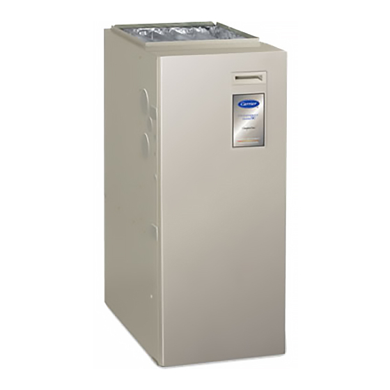
58MVB
Deluxe 4---Way
Multipoise Variable---Capacity
Condensing Gas Furnace
Service and Maintenance Instructions
NOTE: Read the entire instruction manual before starting the
installation.
TABLE OF CONTENTS
. . . . . . . . . . . . . . . . . . . . . . . . . . . . . . . . . . . . . . . .
. . . . . . . . . . . . . . . . . . . . . . . . . . . . . . . .
. . . . . . . . . . . . . . . . . . . . . . . . . . . . . . . . . . . .
. . . . . . . . . . . . . . . . . . . . . . . . . . . . . .
. . . . . . . . . . . . . . . . . . . . . . . . . . . . .
!
ELECTRICAL SHOCK, FIRE, OR EXPLOSION
HAZARD
Failure to follow safety warnings exactly could result in
dangerous operation, personal injury, death, or property
damage.
Improper servicing could result in dangerous operation,
serious injury, death, or property damage.
- - Before servicing, disconnect all electrical power to
furnace.
- - When servicing controls, label all wires prior to
disconnecting. Reconnect wires correctly.
- - Verify proper operation after servicing.
For Sizes 040-- 120, Series 100
PAGE
. . . . . . . . . . . . . . . . . . . . . . . .
. .
. . . . . . . . . . . . . . . . . . . . . . . .
. . . . . . . . . . . . . . . . .
. . . . . . . . . . . . . . .
. . . . . . . . . . . . . . . . . . . . . . . . .
. . . . . . . . . .
. . . . . . . . . . . . . . . . . . . . . . .
. . . . . . . . . . . . . . . . . . . . . .
. . . . . . . .
!
ELECTRICAL SHOCK, FIRE, OR EXPLOSION
HAZARD
1
Failure to follow this warning could result in possible
damage to this equipment, serious personal injury, or death.
2
The ability to properly perform maintenance on this
2
equipment requires certain expertise, mechanical skills,
3
tools, and equipment. If you do not possess these, do not
attempt to perform any maintenance on this equipment
3
other than those procedures recommended in the User's
4
Manual.
5
6
!
7
8
FIRE OR EXPLOSION HAZARD
9
Failure to follow this warning could cause corrosion of
10
heat exchanger, fire, personal injury, or death.
10
Never store anything on, near, or in contact with the
furnace, such as:
12
1. Spray or aerosol cans, rags, brooms, dust mops,
12
vacuum cleaners, or other cleaning tools.
2. Soap powders, bleaches, waxes or other cleaning
compounds, plastic or plastic containers, gasoline,
kerosene, cigarette lighter fluid, dry cleaning fluids, or
other volatile fluids.
3. Paint thinners and other painting compounds, paper
bags, or other paper products.
SAFETY CONSIDERATIONS
Recognize safety information. This is the safety- -alert symbol
.
When you see this symbol on the furnace and in
instructions or manuals, be alert to the potential for personal
injury.
Understand the signal words DANGER, WARNING, and
CAUTION. These words are used with the safety- -alert symbol.
DANGER identifies the most serious hazards which will result in
severe personal injury or death. WARNING signifies a hazard
which could result in personal injury or death. CAUTION is used
to identify unsafe practices which may result in minor personal
injury or product and property damage. NOTE is used to
highlight suggestions which will result in enhanced installation,
reliability, or operation.
1
WARNING
WARNING
Advertisement
Table of Contents

Related Manuals for Carrier Deluxe 58MVB


Summary of Contents for Carrier Deluxe 58MVB
-
Page 1: Table Of Contents
58MVB Deluxe 4---Way Multipoise Variable---Capacity Condensing Gas Furnace Service and Maintenance Instructions For Sizes 040-- 120, Series 100 NOTE: Read the entire instruction manual before starting the WARNING installation. TABLE OF CONTENTS ELECTRICAL SHOCK, FIRE, OR EXPLOSION PAGE HAZARD SAFETY CONSIDERATIONS . -
Page 2: General
Installing and servicing heating equipment can be hazardous due Follow all safety codes including the National Fuel Gas Code to gas and electrical components. Only trained and qualified (NFGC) NFPA 54- -2005/ANSI Z223.1- -2005 in the USA, CSA service agency personnel should install, repair, or service heating B149.1- -05 National Standard of Canada, Natural Gas and equipment. -
Page 3: Care And Maintenance
recharges your body with static electricity (for example; 1. Turn off electrical supply to furnace. DO NOT move or shuffle your feet, DO NOT touch un- 2. Remove filter cabinet door. grounded objects, etc.). 3. Slide filter out of cabinet. 4. -
Page 4: Blower Motor And Wheel Maintenance
BURNER ENCLOSURE PRESSURE REFERENCE TUBE ASSEMBLY COLLECTOR BOX TUBE PLUG (PINK) COLLECTOR BOX COLLECTOR BOX TUBE (GREEN) DRAIN TUBE (BLUE & WHITE STRIPED) INDUCER HOUSING (MOLDED) DRAIN TUBE (BEHIND COLLECTOR BOX DRAIN TUBE) CONDENSATE TRAP COLLECTOR BOX DRAIN TUBE (BLUE) FIELD-INSTALLED FACTORY-SUPPLIED DRAIN TUBE COUPLING (RIGHT... -
Page 5: Cleaning Burners
(1.) Connect 1 tube (blue or blue and white striped) 9. Remove screws that secure manifold to burner box. (See from collector box. Fig. 6.) (2.) Connect 1 tube (violet or unmarked) from inducer NOTE: Do not remove burner box from cell panel. housing. -
Page 6: Cleaning Heat Exchangers
15. Reinsert the igniter wires in the slot in the manifold grom- CAUTION met, dressing the wires to ensure there is no tension on the igniter itself. (See Fig. 7.) UNIT DAMAGE HAZARD WARNING Failure to follow this caution may result in furnace component damage. -
Page 7: Flushing Collector Box And Drainage System
CAUTION UNIT MAY NOT OPERATE Failure to follow this caution may result in improper or intermittent unit operation. The ground wire from the gas valve MUST be attached to the burner box attachment screw. NOTE: Be sure burner box gasket is installed between burner box and cell panel. -
Page 8: Servicing Hot Surface Igniter
TUBE ROUTING Furnace is shipped from factory in upflow configuration. Pressure tube and drain tube routing MUST match the diagrams below. Tube location when used in UPFLOW application Condensate Trap on LEFT Condensate Trap; Factory Installed Side Optional in Blower Shelf BURNER ENCLOSURE PRESSURE (Blower access panel removed) BURNER ENCLOSURE PRESSURE... -
Page 9: Electrical Controls And Wiring
a. Using an ohm meter, check resistance across both IGNITER EXTENDED IGNITER igniter leads in connector. BRACKET HANDLE b. Cold reading should be between 40 ohms and 70 BRACKET 9/16˝ ohms. 5. Remove igniter assembly. a. Remove burner box cover. b. -
Page 10: Checking Heat Tape Operation (If Applicable)
The electrical ground and polarity for 115- -v wiring must be CAUTION maintained properly. Refer to Fig. 15 for field wiring information and to Fig. 21 for unit wiring information. UNIT AND PROPERTY DAMAGE Failure to follow this caution may result in furnace component failures or water property damage. - Page 11 FIELD 24-VOLT WIRING FIELD 115-, 208/230-, 460-VOLT WIRING FACTORY 24-VOLT WIRING FACTORY 115-VOLT WIRING NOTE 2 1-STAGE THERMOSTAT FIVE FIELD-SUPPLIED TERMINALS WIRE FUSED DISCONNECT THREE-WIRE 208/230- OR HEATING- 460-VOLT ONLY THREE PHASE 208/230- W/W1 VOLT NOTE 1 SINGLE Y/Y2 115-VOLT FIELD- JUNCTION PHASE SUPPLIED...
-
Page 12: Wiring Diagrams
Before removing blower access panel or turning off 115- -v power, look into blower access panel sight glass for current LED status. 1. To retrieve status code, proceed with the following: NOTE: NO thermostat signal may be present at furnace control and all blower time delay periods must be completed. - Page 13 A99118 Fig. 18 --- Inducer Housing Drain Tube A99119 Fig. 19 --- Funnel in Drain Tube and Antifreeze Running Through Trap...
- Page 14 A06562 Fig. 20 --- Service Label NOTE: i. Turn setup switch SW1- -1 to OFF position. The component test feature will not operate if the furnace control is receiving any thermostat signals or until all j. Remove tape to release blower access panel door time delays have expired.
- Page 15 (5.) Manually close blower access panel door switch. NOTE: To repeat component test, turn setup switch SW1- -6 to Use a piece of tape to hold switch closed. OFF and then back to ON. b. When items (1) through (5) above have been c.
- Page 20 Printed in U.S.A. Edition Date: 01/07 Catalog No:58MVB- - 2SM Copyright 2007 Carrier Corp. S 7310 W. Morris St. S Indianapolis, IN 46231 Replaces:58MVB- -1SM Manufacturer reserves the right to change, at any time, specifications and designs without notice and without obligations.
Need help?
Do you have a question about the Deluxe 58MVB and is the answer not in the manual?
Questions and answers