
Subscribe to Our Youtube Channel
Related Manuals for Lorex 12” B&W 4 CHANNEL OBSERVATION SYSTEM


Summary of Contents for Lorex 12” B&W 4 CHANNEL OBSERVATION SYSTEM
-
Page 1: Instruction Manual
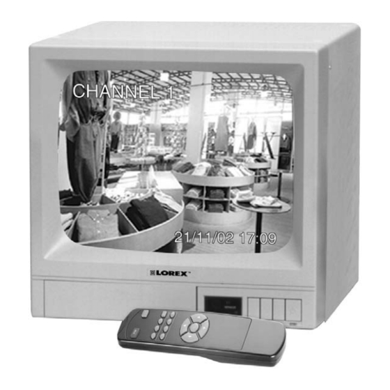
INSTRUCTION MANUAL 12” B&W 4 CHANNEL OBSERVATION SYSTEM SEE WHAT YOU ’ VE BEEN MISSING SEE WHAT YOU ’ VE BEEN MISSING BEFORE OPERATING THIS UNIT, PLEASE READ THIS MANUAL THOROUGHLY AND RETAIN IT FOR FUTURE REFERENCE... - Page 2 FUTURE REFERENCE Thank you for purchasing the 12” B&W 4 Channel Observation system . LOREX is committed to providing our customers with a high quality, reliable security product that customers have come to expect from us. To learn more about this 12” B&W 4 Channel Observation system and to learn about our complete range of accessory products, please visit our website at: www.strategicvista.com...
- Page 3 NOTE This equipment has been certified and found to comply with the limits regulated by FCC, EMC and LVD. Therefore, it is designed to provide reasonable protection against interference and will not cause interference with other appliance usage. However, it is imperative that user follows this manual's guidelines to avoid improper usage which may result in damage to the unit, electrical shock and fire hazard or injury.
-
Page 4: Table Of Contents
13. APPENDIX - A ALARM CONNECTION -------------------------------------------------- 14. APPENDIX - B CONNECTING MONITOR TO A VCR ------------------------------- 15. APPENDIX - C WIRING CONNECTION. -------------------------------------------------- 16. APPENDIX - D CONNECTING TO A LOREX TIME LAPSE VCR FOR NORMAL REC.--------------- 17. LOREX PRODUCT WARRANTY ------------------------------------------------------- 18. -
Page 5: General Precautions
GENERAL PRECAUTIONS 15.Servicing 1. Read Instructions Do not attempt to service this product yourself All of the safety and operating instructions should as opening or removing covers may expose be read and understood before the product is used. you to voltage or other hazards. Refer all 2. -
Page 6: Cautions And Features
CAUTIONS 1. All the warnings and instructions of this manual should be followed 2. Remove the plug from the outlet before cleaning. Do not use liquid aerosol detergents. Use water damped cloth for cleaning 3. Do not use this unit in very humid and wet places 4. -
Page 7: System
SYSTEM INCLUDES 12” B&W 4CHANNEL MONITOR 4-65 Ft CABLE INCLUDED B/W PIR MOTION SENSOR CAMERA (MODEL SG7011SX – 4 CAMERAS AND 4 METAL STAND INCLUDED) (1 Cable included with (1 Camera included with model model SG1241 & 2 SG1241 & 2 with SG1242) with SG1242) -
Page 8: Monitor Controls - Front Panel
MONITOR CONTROLS - FRONT PANEL 1. Brightness Control - Adjusts brightness of picture.Turn knob to reach desired brightness level. 2. Contrast Control - Adjusts contrast of picture. Turn knob to reach desired contrast level. 3. Alarm control button – The sound level of alarm can be adjusted in three levels as desired. Alarm Off - Mutes the alarm. - Page 9 7. VCR button – This button will change the display from the camera inputs to the VCR audio/video playback and recording signal.Note:The surveillance system is designed to work on a professional Time lapse VCR only. 8. Extra button – The button will change the display from the camera inputs to the EXTRA camera signal installed in BNC Jack on rear panel.
- Page 11 1. Channel name set – This option allows the user to title each of the four camera locations. A total of 8 letters / characters can be used. Use the Volume and channel control buttons on the control panel to move and set the titles or to save these settings move the cursor to the EXIT button and press the Menu button.You can also use the Remote control to set the Title.
-
Page 12: Monitor Controls - Back Panel
MONITOR CONTROLS - BACK PANEL 1. AC Input - This Cord is used to connect the supplied power cord from the monitor to an electrical outlet. AC 100V ~ 240V, 50/60Hz. 2. Power Switch(main power switch) - This button controls power to the entire unit. Depress the side with the ‘I’, to turn power ON. -
Page 13: Remote Control
REMOTE CONTROL Listed below are the features of the Remote Control. For more details on specific remote control features, refer to the Monitor feature section. FUNCTION DESCRIPTION ST/BY Turns monitor ON / OFF Sets monitor to VCR Mode Sets OFF the alarm or sets it ALRE Select extra camera DOOR... -
Page 14: Standard B&W
STANDARD B&W Camera Lens - Delivers high quality image by using a 1/3’’ CCD Image Sensor Microphone - Picks up sound around the camera Camera Inputs - Connects cable to monitor Speaker - Delivers sound from the monitor to the camera Bracket - Metal bracket connects to camera for mounting to walls, ceilings or table PIR Sensor - Detects movement / motion. -
Page 15: Monitor Connections
MONITOR CONNECTIONS 1. Camera 1 input Connect one end of the supplied 65ft cable to the first wired camera and the other end to the camera 1 input 2. Camera 2 input Connect one end of the supplied 65ft cable to the first wired camera, the other end to camera 2 input 3. -
Page 16: Technical Specifications
TECHNICAL SPECIFICATIONS MONITOR Picture Tube 12” B&W Horizontal resolution 600 lines Camera Capable Up to four (4 DIN) Camera Input 4 6 pin DIN Control power, seq, Talk, VCR, brightness, Contrast,volume,time,alarm set. Input signal 1 V p-p at 75 ohms terminated Power Source Multi-voltage (AC100V –... -
Page 17: Optional Accessories
OPTIONAL ACCESSORIES The following accessories are available to add to your existing system. CABLE TIME LAPSE RECORDER Extends viewing length from 24 Hour Real Time or 960 Hour Camera to monitor. Available Time Lapse VCR. Records key In 65, 100 and 250 ft lengths events ACCESSORY SUNSHADE HOUSING NIGHTVISION... -
Page 18: Appendix - A Alarm Connection
APPENDIX - A PIN SPECIFICATION OF CABLE COLOR DESCRIPTION WHITE VIDEO SIGNAL BLACK AUDIO(monitor to camer) BLUE N.C. GREEN AUDIO B+ AUDIO(monitor to camer) YELLOW AUDIO B+ ‘SHIELD’ GROUND TO PIR SENSOR PROCEDURE Connection PIR SENSOR to Camera sensor terminal. NOTE Ensure correct connections. -
Page 19: Appendix - B Connecting Monitor To A Vcr
APPENDIX - B TO CAMERA CONNECTIONS PROCEDURE Connect Monitor to Cameras, using 6 pin din cable supplied. NOTE Each pin should match. So that the arrow marks are to the top upside on the Din cable when connecting the cable to Monitor or Camera terminal. -
Page 20: Appendix - C Wiring Connection
APPENDIX - C Connection Diagrams PROCEDURES 1. Connect VCR & Slave Monitor (optional) to main Monitor with RCA cables (not supplied). 2. Connect Camera to Monitor with 65ft DIN cable supplied. (Connect PIR sensor to Camera terminal(optional)) 3. Connect Extra Camera optionally with BNC plug (not supplied). 4. -
Page 21: For Normal Rec
APPENDIX - D CONNECTING TO A LOREX TIME LAPSE VCR FOR NORMAL RECORDING -18-... -
Page 22: Lorex Product Warranty
This warranty is invalidated if other than Lorex accessories are or have been used in or in connection with the Product or in any modification or repair is made to the Product be other than a service depot authorized by Lorex. -
Page 23: Care And Maintenance
CARE AND MAINTENANCE Please follow the following instructions to ensure proper care and maintenance of this system Keep your monitor and camera dry. If it gets wet, wipe it dry immediately. Use and store your unit in normal temperature environment. Extreme temperatures can shorten the life of the electronic devices.
Need help?
Do you have a question about the 12” B&W 4 CHANNEL OBSERVATION SYSTEM and is the answer not in the manual?
Questions and answers