Table of Contents
Advertisement
Quick Links
Advertisement
Table of Contents

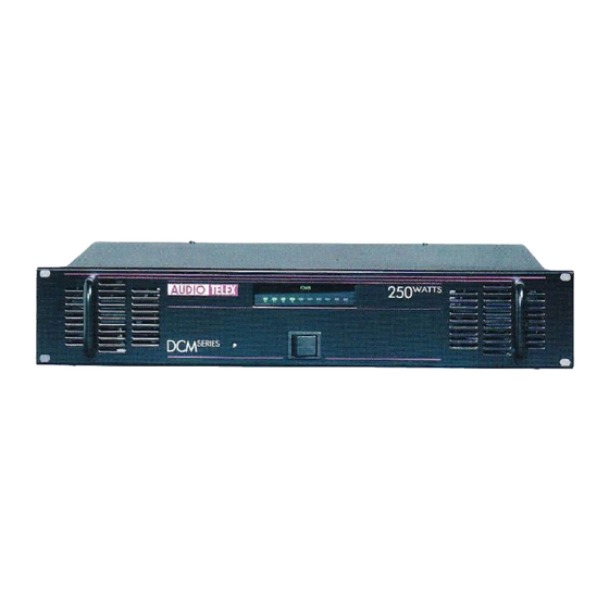
Summary of Contents for AUDIO TELEX DCM250
-
Page 1: Service Information
SERVICE INFORMATION AUDIO TELEX DCM250 POWER AMPLIFIER CONTENTS: OPERATION MANUAL CIRCUIT DESCRIPTION SET-UP / TEST PROCEDURE SCHEMATIC DIAGRAMS PCB OVERLAYS COMPONENT LISTS Australian Monitor 1 Clyde Street, Silverwater NSW 2128 Australia +61 2 9647 1411 www.australianmonitor.com.au... -
Page 6: Power Switch
To set the current limit: 1. Reset the trimpot P1 turning fully clockwise. 2. Connect the amplifier to half it’s minimum load (10ohm for DCM500, 20ohm for DCM250, 40ohm for DCM120). 3. Run an rms 1kHz sine wave into the amplifier and set the input level so that you read 425mVDC (DCM250/500) or 825mVDC (DCM120) across the emitter resistor, measuring the side which has the higher current (measured as a voltage across the emitter resistors). -
Page 7: Power Amp
The thermal cutout and fan is controlled by a microprocessor (PIC12C509A). The temperature is sensed using a 10k@25degC NTC. The fan is normally off and turns on to full speed at 60degC. This temperature is fixed and not adjustable. The thermal cutout temperature is set using the trimpot accessible through the hole in the top left side of the chassis return (only visible with the lid off). -
Page 8: Fuse Sizes
DCM120 – 80 ohms DCM250 – 40 ohms DCM500 – 20 ohms XLR Audio Input and Parallel Output The DCM series includes both male and female 3 pin XLR connectors per channel. While the female is normally used as the input to the amplifier, both XLR’s are connected in parallel so either will work. -
Page 9: Electrical Check
7815 output = 15.5V 2.6 Give input signal of 500 mV to get outputs as follows (@ 4Ω output load)/ 22V for DCM 120, 32VAC for DCM250, 44.7VAC for DCM 500. Check 100V O/p at 100vV line, Remove the input signal... -
Page 10: Final Testing
8. Overload setting: - Check the DC voltage at the emitter resistors having the maximum voltage value. Increase input signal to get 820mV for DCM 120, 425mV (for DCM250 & DCM 500). Turn preset (P2) anticlockwise such that it just mutes the output signal and signal returns back slowly after 2 seconds. - Page 16 R15B R16B R17B R18B R19B R20B R21B R22B R23B 150R 150R R42B R38B 11 X TIP35C 220R 220R R36B 500R +35V PCB6201 220R DCM250 POWER PCB Title CD6201-2 Size Number Revision Date: 7-May-2003 Sheet of File: C:\DCM Manuals\CD6201-21.DDB Drawn By:...
- Page 17 Microprocessor Mute/Limiter/Drive 100P PIC12C509 IC3A R16 2M2 SA571 X3/1 X1/1 680R R35 33K X1/2 BC639 100K X1/3 .47u IC4B LM833-B Desc GP0-OUT = 1/2VCC CON X2/1 100R (N/C) AGND GP1-OUT = FAN CON 100K IC2A LM358 GP2-OUT = PRTCT/MUTE GP3-IN = I LIMIT GP4-IN = FAN SENSE...
- Page 18 BATTERY +35VDC 6.3A SB 240AC IN 10000U 0.15u PCB6203 DCM250 POWER SUPPLY Title CD6203-2 Size Number Revision Date: 6-May-2003 Sheet of File: C:\DCM Manuals\CD6203-2.DDB Drawn By:...
- Page 22 DCM250 Output Stage Component List Designator Part Type Description 820P Multi layer Ceramic capacitor 820P Multi layer Ceramic capacitor 1N4007 Rectifier Diode 1N4007 Rectifier Diode 1N4007 Rectifier Diode 1N4007 Rectifier Diode 1N4007 Rectifier Diode 1N4007 Rectifier Diode 1N4007 Rectifier Diode...
- Page 23 220R Resistor, metal film .5W Resistor, metal film .5W R40B Resistor, metal film .5W R41A 100D R42B Resistor, metal film .5W Resistor, metal film .5W Resistor, metal film .5W 150R Resistor, metal film .5W 150R Resistor, metal film .5W 150R Resistor, metal film .5W 150R Resistor, metal film .5W...
- Page 24 DCM Series Drive Stage Component List Designator Part Type Description Electrolytic Capacitor 35V Electrolytic Capacitor 35V Electrolytic Capacitor 35V Electrolytic Capacitor 35V Multi layer ceramic capacitor Multi layer ceramic capacitor 100u Electrolytic Capacitor 16V 100u Electrolytic Capacitor 16V Electrolytic Capacitor 35V Electrolytic Capacitor 35V Electrolytic Capacitor 35V Electrolytic Capacitor 35V...
- Page 25 Link, zero ohms Link, zero ohms Link, zero ohms Link, zero ohms Cermet, preset Horizontal Potentiometer 16mm Cermet, preset Horizontal Resistor, metal film .5W Resistor, metal film .5W 390R Resistor, metal film .5W 100R Resistor, metal film .5W Resistor, metal film .5W Resistor, metal film .5W 100K Resistor, metal film .5W...
- Page 26 Driver Transformer RF2285B Driver Transformer BC639 Transistor TO92 BC639 Transistor TO92 BC546 Transistor TO92 BC556 Transistor TO92 BC546 Transistor TO92 BC546 Transistor TO92 BC546 Transistor TO92 BC556 Transistor TO92 BC556 Transistor TO92 Please note * DCM120-DCM500 ** DCM250 Please note...


Need help?
Do you have a question about the DCM250 and is the answer not in the manual?
Questions and answers