Table of Contents
Advertisement
Quick Links
Download this manual
See also:
Operating Instructions
Advertisement
Table of Contents

Related Manuals for AUDIO TELEX IC30


Summary of Contents for AUDIO TELEX IC30
-
Page 1: Service Information
SERVICE INFORMATION AUDIO TELEX IC30 MIXER AMPLIFIER CONTENTS: OPERATION MANUAL SCHEMATIC DIAGRAMS BOARD OVERLAY PARTS LISTING TEST PROCEDURE Australian Monitor 1 Clyde Street, Silverwater NSW 2128 Australia +61 2 9647 1411 www.australianmonitor.com.au... -
Page 2: Ac Power Inlet
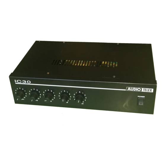
DC power supply source. The amplifier is supplied free standing with rubber feet but can be rack mounted via an optional rack mount kit (IC30RMK). The IC30 will deliver 30 watts into a load of 4 ohms, 70 volt or 100 volt line. -
Page 3: Phantom Power
Activation is via contact closures which may be wired to the rear panel of the IC30 or to external switches or a timer. Full installation instructions are provided with the tone generator. -
Page 4: Fuse Sizes
Rack Mouting Kit An optional rack mounting kit (IC30RMK) is available to mount the IC30 in a standard 19" equipment rack. Fuse Sizes Mains 230 VAC: 1 Amperes Slow Blow The DC fuse is located on the circuit board. This is a feature of the AMIS series amplifiers, which are equipped with a current limiting circuit preventing excessive DC currents, thus eliminating the risk of blowing high tension fuses. - Page 5 TDA1516 680R MIC3 LM1458 IC2A 680R +12V +10V 330P MUTE 4A SB +14V +12V BATTERY 1A SB BD139 D2-D5 240VAC +10V 100u 470u Title IC30 MIX/POWER PCB Size Number Revision CD6168-1 Date: 21-Oct-2002 Sheet of File: C:\Protel Files\CDTRAX\CD6168-1.DDB Drawn By:...
- Page 6 TDA1516 680R MIC3 LM1458 IC2A 680R +12V +10V 330P MUTE 4A SB +14V +12V BATTERY 0.5A SB BD139 D2-D5 240VAC +10V 100u 470u IC30 MIX/POWER PCB Title CD6168-1 Size Number Revision Date: 4-Jul-2003 Sheet of File: C:\AMIS604 Manual\CD6168-1.DDB Drawn By:...
- Page 8 IC30 Parts List Designator Part Type Description Manufacturer's Code Electrolytic capacitor 63V 2121280010 Electrolytic capacitor 63V 2121280010 330P Multi layer ceramic capacitor 100V 2127181331 330P Multi layer ceramic capacitor 100V 2127181331 Electrolytic capacitor 63V 2121280010 Electrolytic capacitor 63V 2121280010 Electrolytic capacitor 63V...
- Page 9 4.0A 4.0 Amp Anti-surge Fuse 2541210840 LM1458 IC Dual Op Amp DIP8 2152870558 LM1458 IC Dual Op Amp DIP8 2152870558 4066 I.C. CD 4066BCN VCA (14 PIN) 2159440066 TDA1516 Amplifier IC TDA1516BQ 2153121516 TDA1516 Amplifier IC TDA1516BQ 2153121516 LM741 LM741 IC 2152080741 Transistor BD139 2141400139...
- Page 10 Resistor, metalfilm .5W 9111590472 Potentiometer linear 2021000503 Resistor, metalfilm .5W 9111590473 Rocker switch SPST 2511213112...
- Page 11 WORK INSTRUCTION Testing of IC 30 1. Perform physical inspection ( Visual Inspection stage ) 1.1 Check : • All screws for tightness ( esp. H/S & IC fixing). • Capacitors for polarity. • Earth connection for good contact (XLR gnd to AC earth), including earthing of RCA’s, •...
- Page 12 5. Function Checks (Final stage). 5.1 Move signal generator to Mic2. Turn up volume control. Watch for irregularities. Check for 10.5V out. 5.2 Move signal generator to Mic3. Turn up volume control. Watch for irregularities. Check for 10.5V out. 6. Line level inputs (Final stage). 6.1 Connect signal generator to Line1 input.
- Page 13 WORK INSTRUCTION Testing of IC 30 1. Perform physical inspection ( Visual Inspection stage ) 1.1 Check : • All screws for tightness ( esp. H/S & IC fixing). • Capacitors for polarity. • Earth connection for good contact (XLR gnd to AC earth), including earthing of RCA’s, •...
- Page 14 5. Function Checks (Final stage). 5.1 Move signal generator to Mic2. Turn up volume control. Watch for irregularities. Check for 10.5V out. 5.2 Move signal generator to Mic3. Turn up volume control. Watch for irregularities. Check for 10.5V out. 6. Line level inputs (Final stage). 6.1 Connect signal generator to Line1 input.
Need help?
Do you have a question about the IC30 and is the answer not in the manual?
Questions and answers