Table of Contents
Advertisement
Quick Links
Advertisement
Table of Contents

Summary of Contents for AUDIO TELEX DCM120
-
Page 1: Service Information
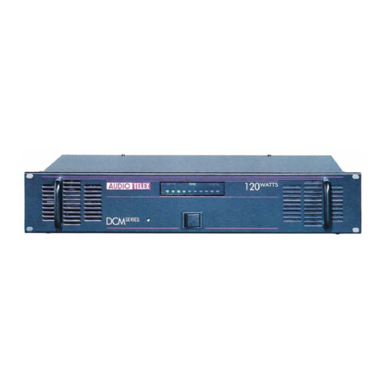
SERVICE INFORMATION AUDIO TELEX DCM120 POWER AMPLIFIER CONTENTS: OPERATION MANUAL CIRCUIT DESCRIPTION SET-UP / TEST PROCEDURE SCHEMATIC DIAGRAMS PCB OVERLAYS COMPONENT LISTS Australian Monitor 1 Clyde Street, Silverwater NSW 2128 Australia +61 2 9647 1411 www.australianmonitor.com.au... - Page 2 ff{lTl AUlilrDililt@ co M M u N CATI SPrar www.audiotelex.com .fr, DCMl Amplifier 120w Power Ouditv EndorseA "ffiiH io Tel"1$pJnn"y,3j":"?ljons Pty Ltd NSW & ACT Beaconsfield Street Commercial Road Middleborough Road 221277 Private Bag 149 HillVlC 3128 .frl Silverwater NSW 2128 Fortitude Valley QLD 4006 Australia...
- Page 3 Turning the control Series clockwise the output of the DCM120 increase it's maxim'm towards output level while turning will the control cormter-clockwise contol the output level. Adjust this decrease...
- Page 4 PoWef: This LED glows green power to the DCM120. Note that this not indicate switched does pres€nce supply voltage tlains Failure: will glows ftilure in power there...
- Page 5 tll!||l||tl lllllillil! llll||l!iiil (-'.' ilIB a----------------) -_-------- c---------------) c-----------) -_----------) ---- (.------------ -__- (--__--------- ililil!lr!llil l||l||ll!tl ltll||l!tl!
-
Page 6: Power Switch
3. Run an rms 1kHz sine wave into the amplifier and set the input level so that you read 425mVDC (DCM250/500) or 825mVDC (DCM120) across the emitter resistor, measuring the side which has the higher current (measured as a voltage across the emitter resistors). -
Page 7: Power Amp
Common or “-” for low impedance speaker loads (4 or 8 ohms) Positive “+” for 4 ohm speaker loads (use with common) Positive “+” for 8 ohm speaker loads (use with common) DCM120 only Common or “-” for 70v or100v speaker loads Positive “+”... -
Page 8: Fuse Sizes
DCM120 – 80 ohms DCM250 – 40 ohms DCM500 – 20 ohms XLR Audio Input and Parallel Output The DCM series includes both male and female 3 pin XLR connectors per channel. While the female is normally used as the input to the amplifier, both XLR’s are connected in parallel so either will work. - Page 9 TESTING PROCEDURE OF DCM 120/DCM 250/DCM 500 I. PRE-TESTING (of complete sets). • Check 1.1 All screw for tightness (Bridge rectifier and transistor bolts) 1.2 Earth Connection for good contact (solder and crimpling) 1.3 This setup has signal input to the Amplifier through male (XLR) 1.4 Check with Multimeter that there is a DC resistance of about 250 Ω...
-
Page 10: Final Testing
II. FINAL TESTING (This setup should have signal input to Amplifier through female (XLR) (The limiter link should be out of circuit initially.) 1. Connect the Amplifier to the setup, set voltage selector switch to 240V 2. Switch ON the set to 240VAC. 3. - Page 14 NOT USED BC556 470R 820P TO X7 150R 150R IRF9520 BATTERY TIP35C TIP35C +35VDC 240AC IN 220R 220R TIP41C 10000U +35V 500R 100R DCM120 POWER PCB Title CD6206-1 Size Number Revision Date: 8-May-2003 Sheet of File: C:\DCM Manuals\CD6206-12.DDB Drawn By:...
- Page 15 IC6/P2 FAN CONTROL BC546 IC6/P6 IC6/P3 X2/4 X4/3 X4/1 PROTECT POWER Power Current Limit 16VDC 7815 7805 X2/3 X4/2 X2/2 R41=15K=DCM120/500 470K BC556 100u R41=12K=DCM 250 X4/6 IC6/P4 X4/5 100u BC546 AGND 100u AGND IC6/P7 Title BC546 DCM DRIVER Size...
- Page 18 DCM120 Output Component List Designator Part Type Description KBPC 3506 Bridge rectifier 400V 35A 820P Multi layer Ceramic Capacitor 820P Multi layer Ceramic Capacitor 15,000uF Electrolytic Capacitor 50V LED Green 3.0mm 1N4148 Diode Rectifier 1N4007 Diode Rectifier 1N4148 Diode Rectifier...
- Page 19 Not Used Metal film resistor .5W Metal film resistor .5W Metal film resistor .5W 150R Metal film resistor .5W 150R Metal film resistor .5W Metal film resistor .5W Metal film resistor .5W Switch Switch DPST Switch Switch DPST Mains XFMR Mains Transformer Output XFMR Output transformer TIP41C...
- Page 20 DCM Series Drive Stage Component List Designator Part Type Description Electrolytic Capacitor 35V Electrolytic Capacitor 35V Electrolytic Capacitor 35V Electrolytic Capacitor 35V Multi layer ceramic capacitor Multi layer ceramic capacitor 100u Electrolytic Capacitor 16V 100u Electrolytic Capacitor 16V Electrolytic Capacitor 35V Electrolytic Capacitor 35V Electrolytic Capacitor 35V Electrolytic Capacitor 35V...
- Page 21 Link, zero ohms Link, zero ohms Link, zero ohms Link, zero ohms Cermet, preset Horizontal Potentiometer 16mm Cermet, preset Horizontal Resistor, metal film .5W Resistor, metal film .5W 390R Resistor, metal film .5W 100R Resistor, metal film .5W Resistor, metal film .5W Resistor, metal film .5W 100K Resistor, metal film .5W...
- Page 22 Driver Transformer RF2285B Driver Transformer BC639 Transistor TO92 BC639 Transistor TO92 BC546 Transistor TO92 BC556 Transistor TO92 BC546 Transistor TO92 BC546 Transistor TO92 BC546 Transistor TO92 BC556 Transistor TO92 BC556 Transistor TO92 Please note * DCM120-DCM500 ** DCM250 Please note...


Need help?
Do you have a question about the DCM120 and is the answer not in the manual?
Questions and answers