Table of Contents
Advertisement
Quick Links
Effective September 2010 –
QUICK LOAD™ Liners Standard
on all TOUGH GUN™ Robotic MIG Guns
TECHNICAL GUIDE
TOUGH GUN™ ThruArm™
G1 Series Robotic MIG
Guns for KUKA® Robots
KR 5 arc HW
INSTALLATION
MAINTENANCE
TECHNICAL DATA
OPTIONS
EXPLODED VIEW & PARTS
LIST
ORDERING INFORMATION
Certified ISO 9001 : 2008
Please read instructions prior to use.
Save this manual for future reference
Advertisement
Table of Contents

Related Manuals for Tregaskiss G1 Series


Summary of Contents for Tregaskiss G1 Series
- Page 1 TECHNICAL GUIDE TOUGH GUN™ ThruArm™ G1 Series Robotic MIG Guns for KUKA® Robots KR 5 arc HW INSTALLATION MAINTENANCE TECHNICAL DATA OPTIONS EXPLODED VIEW & PARTS LIST ORDERING INFORMATION Effective September 2010 – QUICK LOAD™ Liners Standard on all TOUGH GUN™...
-
Page 2: Table Of Contents
7.0 – ORDERING INFORMATION .......................... 14 THANK YOU... …for selecting a Tregaskiss TOUGH GUN™ ThruArm™ G1 Series Robotic MIG Gun. Manufacturing operations demand extremely dependable robotic equipment. With this in mind, the TOUGH GUN™ MIG Gun was designed and engineered to be a reliable tool to support high production within a robotic cell. As the name implies, the TOUGH GUN MIG Gun is made from durable materials and components engineered to perform in a rugged welding environment. -
Page 3: General Safety Information
Buyer after notification by Customer Service. Tregaskiss makes no other warranty of any kind, expressed or implied, including, but not limited to the warranties of merchantability or fitness for any purpose. Tregaskiss shall not be liable under any circumstances to Buyer, or... -
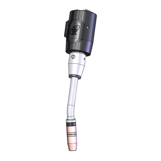
Page 4: Complete Assembly Overview
1.0 – COMPLETE ASSEMBLY OVERVIEW LSR UNICABLE QUICK LOAD™ POWER LINER AND RETAINER THRUARM CLUTCH ASSEMBLY NECK RETAINING HEAD CONTACT TIP NOZZLE For part numbers, please see Section 6.0 EXPLODED VIEW AND PARTS LIST. -
Page 5: Installation
2.0 – INSTALLATION CONNECTOR NECK INSULATING DISC CONSUMABLES HOUSING OUTER COVER STEP #1 - POSITIONING THE ROBOT Position the robot with the wrist and top axis as shown to properly complete the gun installation. WRIST TOP AXIS STEP #2 - REMOVING OUTER COVER ... -
Page 6: Step #4 - Connecting Lsr Unicable
Insert Unicable through mounting face of robot (cutaway of robot shown below). Insert Unicable Connector into flange-cable connector. Ensure components are fully seated. Tregaskiss Low Stress Robotic Unicable shown here (See Section 2.0 INSTALLATION) Secure by tightening M6x20 SHCS, using 5 mm Allen key to 80 in.-lbs. (9 Nm). -
Page 7: Step #6 - Installing Power Pin To The Lsr Unicable
STEP #6 - INSTALLING POWER PIN TO THE LSR UNICABLE Option #1 of 2: Power Pins Install power pin onto the LSR Unicable. NOTE: Power pins incorporate a taper to seat and lock the pin to the rear handle block. Make POWER PIN sure the power pin is tightened in the block with (MILLER SHOWN) -
Page 8: Step #8 - Installing Consumables
STEP #8 - INSTALLING CONSUMABLES TOUGH LOCK RETAINING NOZZLE NECK CONTACT TIP HEAD Retaining Head Thread the retaining head onto the neck. Use a 5/8” wrench and tighten to 80 in.-lbs. (or 9 Nm). Contact Tip Thread the contact tip into the retaining head. ... -
Page 9: Maintenance
3.0 – MAINTENANCE 3.1 REPLACEMENT / ADJUSTMENT OF CLUTCH LIMIT SWITCH Feed wires of switch through center holes of switch base and jam nut as shown in exploded view. Thread switch base far enough down on the switch body so that the switch will not bottom out when the assembly is fastened to the clutch. -
Page 10: Replacement Of Quick Load Liner
Insert the two M5 x 6mm countersunk screws and torque to 12 in.-lbs. (1.35 Nm). You may have to rotate the hand nut to access the holes. 3.3 REPLACEMENT OF QUICK LOAD LINER ™ POWER PIN (MILLER SHOWN) LINER RETAINER REAR CAP ... -
Page 11: Technical Data
4.0 – TECHNICAL DATA 4.1 GUN CONFIGURATIONS 22° Neck – 0.59” (15 mm) CTWD 45° Neck – 0.59” (15 mm) CTWD 4.2 CENTER OF MASS 22° NECK 45° NECK 0.14" 0.33" (3.60 mm) (8.38 mm) -4.9" -4.65" (124.46 mm) (-118.11 mm) 3.94 lbs. -
Page 12: Amperage Ratings
4.3 AMPERAGE RATINGS* 60% DUTY CYCLE - MIXED GASES MODEL OR 100% DUTY CYCLE - CO TOUGH GUN ThruArm Series – Air-Cooled 500 amp *Ratings are based on tests that comply with IEC 60974-7 standards. 5.0 – EXPLODED VIEW & PARTS LIST – K5800 PART # DESCRIPTION PART #... -
Page 13: Parts Lists For K5800A, K5800W, & K5800Aw Models
NOTE: Run Air Blast Line through the same hole as the Control Cable. See Technical Guide Addendum M076 Air Blast Installation for ThruArm Series Robotic MIG Guns on our website at www.tregaskiss.com for details or call Tech Services at 1-877-737-3111 for assistance. PART # DESCRIPTION Air Blast Kit (Includes 15’... -
Page 14: Ordering Information
To order replacement parts for your TOUGH GUN ThruArm G1 Series Robotic MIG Gun, please contact your authorized Tregaskiss distributor. For help with configuring a part number for a new TOUGH GUN ThruArm G1 Series Robotic MIG Gun, visit www.tregaskiss.com/ThruArm for a complete list of available options to fill in the 10 digit part number below.
Need help?
Do you have a question about the G1 Series and is the answer not in the manual?
Questions and answers