
Related Manuals for Talkswitch owner friendly

Summary of Contents for Talkswitch owner friendly
- Page 1 ™ TalkSwitch User Guide Release 6.12...
- Page 2 Information in this user guide is subject to change without notice and does not represent any commitment on the part of TalkSwitch. No part of this user guide may be reproduced or transmitted in any form or by any means, electronic or mechanical, including photocopying, recording, or information storage and retrieval systems, or translated to another language, for any purpose other than the licensee’s personal use and, as specifically allowed in the licensing...
-
Page 3: Table Of Contents
Upgrading the TalkSwitch software and firmware ........ - Page 4 Connecting TalkSwitch units to a LAN ........
- Page 5 TalkSwitch TS-550i, TS-480i, TS350i, TS-9133i or TS-9112i ......60 TalkSwitch TS-850i (United States and Canada only) ......61...
- Page 6 Adding TalkSwitch TS-9112i, TS-9133i and TS-480i IP phones ....... 90...
- Page 7 Further configuration ............95 Adding TalkSwitch TS-850i IP phones (United States and Canada only) ......96 Installing the base .
- Page 8 TalkSwitch Line Optimizer........
- Page 9 Open > TalkSwitch Location ........
- Page 10 Configuring TalkSwitch systems ........
- Page 11 Conference calling ............. 209 Two local TalkSwitch extensions and one outside caller......209 Two outside callers and one local extension .
- Page 12 Using a standard phone connected in parallel to TalkSwitch .......
- Page 13 I am not able to retrieve settings from TalkSwitch....... .
- Page 14 Appendix B: TalkSwitch and Telephone Company Services........
- Page 15 Appendix E: TalkSwitch One-Year Warranty and Return Policy ....... . .
-
Page 16: Preface
This preface contains important information to help you minimize your installation effort and to get the most out of the features and the flexibility of your TalkSwitch system. We strive to make your experience with installation and configuration the most rewarding possible. -
Page 17: What You Should Know
WHAT YOU SHOULD KNOW While TalkSwitch is customer installable, certain skills are required if you need to route cables or to configure a network. The following points will help you determine the required skills: • Configuring the TalkSwitch system using the TalkSwitch management software can be performed by anyone with basic computer skills once the system is physically installed with proper networking equipment configurations (if two or more units are networked on a LAN). -
Page 18: Important Information
The equipment will not operate when mains power fails. In the event of a power failure, each TalkSwitch unit will connect extension E4 to phone Line 1 to permit calls (except-AU models). Calls must be dialed without a hunt group. All other TalkSwitch functions will not be available until power is restored. -
Page 19: External Audio Source Isolation
Where to go for further information The guides listed below and other guides can be found on the TalkSwitch software CD, in the TalkSwitch folder in the Windows Start menu once the software has been installed, and in the support section of our website at http://global.talkswitch.com. -
Page 20: Guide Conventions
GUIDE CONVENTIONS The TalkSwitch User Guide uses the following text elements and icons as visual aids, making the manual more accessible. Text elements Italic Italicized text highlights labels within windows, references within the document, and references to other TalkSwitch documents. -
Page 21: Chapter 1: Talkswitch Installation
CD and documentation comes with every unit. Refer to the TalkSwitch Start Guide included with the unit to verify you have everything you need. The package for VoIP-enabled units also contains a VoIP Network Configuration Guide. -
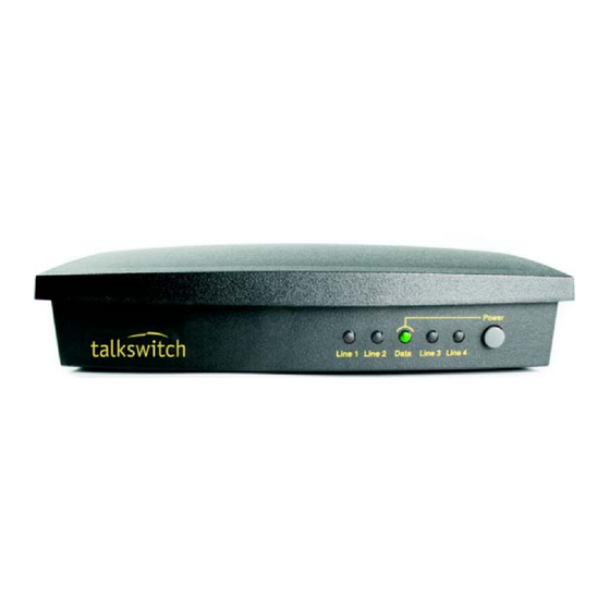
Page 22: Unit Front Panel
This indicator is disabled by default, but can be enabled. TalkSwitch models with eight telephone lines do not have lights for Lines 5 to 8. What the flashing lights mean The TalkSwitch unit flashes the lights on the front panel in different patterns to show diagnostic states. -
Page 23: Line 1 And 3 Lights, Then Line 2 And 4 Lights Flashing Alternately
Line 1 and 3 lights, then Line 2 and 4 lights flashing alternately The firmware and prompts have been updated, and the TalkSwitch unit needs to reboot. 1. Choose Tools > Reboot TalkSwitch or, on the front panel, turn the power button off and back on. -
Page 24: Unit Back Panel
The PF box between E4 and L1 represents power failure support. In the event of a power failure or loss of power to TalkSwitch, extension jack E4 is able to receive and make calls on Line 1. Note: not applicable in Australia. -
Page 25: Installing The Talkswitch Management Software
1. If the TalkSwitch unit is connected to a USB cable, disconnect the cable. 2. Turn on your computer and insert the TalkSwitch CD into your CD drive. The install program starts automatically. 3. Click NEXT and follow the instructions. -
Page 26: Upgrading The Talkswitch Software And Firmware
1. Click Start > Programs > TalkSwitch 6.12 > TalkSwitch Auto Update. If your TalkSwitch management software is due for an update, a window informs you of the status of your software version. If you need an update, you have the option to download the update. -
Page 27: Step 1 - Check Current Version
To find your TalkSwitch software version number, choose Help > About TalkSwitch Management Software. Write down the software number. Go to the support section of the TalkSwitch website at http:// global.talkswitch.com. The instructions help you select and download the appropriate upgrade. -
Page 28: Step 3 - Updating The Firmware
C:\Program Files\TalkSwitch\TalkSwitch Configuration 6.12. INITIAL CONFIGURATION Once your software is installed and your TalkSwitch is connected directly to a PC or via a switch/ hub to the LAN, you can customize the TalkSwitch system with the TalkSwitch management software. -
Page 29: Select Location For Installation
SELECT LOCATION FOR INSTALLATION Select a suitable location for installation of TalkSwitch. TalkSwitch can be installed on a desktop or mounted on a wall. It can be installed in a office or communications or utility room. Choose a location that meets the following requirements: •... -
Page 30: Connect Talkswitch To A Network Or A Pc
1. Connect the cable to a USB port on your PC and to the USB port on the back of TalkSwitch. T A L K S W I T C H I N S T A L L A T I O N... -
Page 31: Internet Connection
(standard phone, cordless phone, fax machine or modem) connected to extension jack E1–E8. An IP extension is an IP phone connected via LAN. An external IP extension is an IP phone connected via the Internet, and requires the TalkSwitch unit to have VoIP capability. -
Page 32: Connecting A Single-Line Analog Phone
Figure 7: Single-line phones Connecting a two-line analog phone You can plug a two-line phone into two extension jacks of the TalkSwitch unit. You can then configure each telephone line to ring a specific extension. For example, line 1 can ring extension 111, which will show Line 1 as active. -
Page 33: Connecting An Ip Phone
A modem connected to a TalkSwitch unit operates at up to 28 kbps. If you don’t want to change your dial-up settings for the modem, enable Direct Line Access for the extension associated to the modem. -
Page 34: Connecting A Fax Machine
Connecting a fax machine If you are connecting a fax machine to a TalkSwitch unit, plug it into an extension jack. TalkSwitch provides you with three options to configure your fax machine. Choose the best option for your office. Option 1 — Dedicated fax line You may already have an incoming dedicated fax line. -
Page 35: Option 3 - Automatic Fax Detection Via The Auto Attendant
The PA jack can be connected to a PA system for overhead paging, screening voicemail and playing music on hold. The PA jack requires a 1/8" (3.5 mm) mono phono connector. If your system has multiple TalkSwitch units, use a splitter to connect each TalkSwitch unit to the PA system. -
Page 36: Internal Audio File
Internal audio file You can load an audio .wav file into the TalkSwitch unit. If you have more than one unit connected by LAN, the .wav file is automatically copied to each unit. -
Page 37: Power Up All The Talkswitch Units
It is important that you place the IP extensions on the same subnet as TalkSwitch. For example, if your TalkSwitch unit has the IP address 192.168.1.200, your IP extensions should use IP addresses in the range 192.168.1.xxx that do not conflict with other IP addresses. -
Page 38: Keep Track Of The Lines And Extensions
ID. It simplifies matters when you need to add or remove extensions and lines. Optimizing the system for networked use TalkSwitch units have been designed to operate optimally when in a networked state. Below are a few items that have been designed for better network use. -
Page 39: Special Considerations When Connecting Multiple Units To A Lan
Special considerations when connecting multiple units to a LAN Multiple TalkSwitch units on a LAN will function as a single phone system. Some features are expanded as you add units, and other features are not. As you add more units, the number of telephone lines, local extensions, VoIP lines, remote extensions and voice mailboxes will increase. -
Page 40: Upgrading Talkswitch Units
VoIP, as well as adding telephone lines and extension jacks. The upgrade kit consists of a top board you add to your existing TalkSwitch unit, as well as a guide containing detailed, step-by-step instructions for the upgrade procedure. -
Page 41: Enabling Licensed Add-Ons
CONNECTING A TALKSWITCH UNIT TO A PBX Connecting a TalkSwitch unit to a PBX allows the TalkSwitch unit to answer calls with an auto attendant. The caller can dial 7 followed by an extension number to reach an extension on the PBX. -
Page 42: Chapter 2: Talkswitch Configuration
Ch ap te r 2 : Ta lk Sw itch Co n fi g u ra ti o n TA LKSW ITCH CO NFIGURATION INTRODUCTION This chapter contains detailed information about all the features in the TalkSwitch management software, with step-by-step instructions on how to customize these features to best suit your needs. - Page 43 Click Connect to Different System. The Connect Via IP window appears. b) Enter the URL / IP address and Port of the TalkSwitch unit, and then click OK. This is the public IP address or FQDN of the TalkSwitch system. The software loads the configuration from the TalkSwitch unit, and the About page appears.
- Page 44 8. To open a configuration file: a) Click Open a Configuration File or Template. The Open File or Template window appears. b) Click Open a File. The Configuration File window appears. c) Browse to the .tsd file, and then click Open. The software opens the configuration file. T A L K S W I T C H C O N F I G U R A T I O N...
-
Page 45: About
See System time on page 31. • The current mode. A mode is a period of time when the TalkSwitch system uses a particular call handling setup for incoming calls. Mode 1 is typically office hours, and Mode 2 is typically evening and weekend hours. - Page 46 IP address, model number, firmware version, and length of operation for each TalkSwitch unit. To identify a TalkSwitch unit, click the Identify button. The Identify button will change to a Stop button. All the lights on the front panel will start flashing. Click the Stop button to end the flashing.
-
Page 47: Administration
CAUTION: Use a system password, otherwise the system will be vulnerable to configuration changes, misuse and/or lock-out by callers or users. If the router has port 9393 mapped to the TalkSwitch unit for remote configuration, the system will also be vulnerable to anyone on the Internet. -
Page 48: Region Selection
TalkSwitch unit will operate. Language The Language area displays the language loaded into the TalkSwitch system, and allows you to load and remove language files. 1. To change the language files loaded into the TalkSwitch system, click Edit. The Language File Management window appears, listing loaded language files. -
Page 49: Scheduling
SCHEDULING A mode is a period of time when the TalkSwitch system uses a particular call handling setup for incoming calls. Mode 1 is typically office hours, and Mode 2 is typically evening and weekend hours. Holiday Mode is when your office is closed for a statutory holiday or shutdown. -
Page 50: Change Mode
c) Click Settings. The Holiday Settings window appears. The calendar shows the current date in green. d) Select your country in the Populate calendar with holidays observed in list, and then click Populate. The calendar will show your country’s statutory holidays in grey. e) Using the calendar, select the month and then click the date of the holiday. -
Page 51: Scheduling
NTP server programmed into the TalkSwitch system. NOTE: You can configure the TalkSwitch system to get the time and date (but not the year or time zone) from caller ID. See Clock Preferences on page 189. -
Page 52: Date & Time
1. Click Adjust. You can also choose Options > Set Date & Time. The TalkSwitch Date and Time Properties window appears. Date & time The Date & Time area allows you to set the date and time programmed into the TalkSwitch system. - Page 53 1. Select the NTP Server tab. 2. Enter the NTP server. T A L K S W I T C H C O N F I G U R A T I O N...
-
Page 54: Ip Configuration
IP addresses. If so, enter the following IP addresses from your LAN administrator: a) Enter a static IP address for each TalkSwitch unit in the Unit IP address boxes. b) Enter the Subnet mask for the LAN. This address determines the subnet the unit IP addresses belong to. -
Page 55: Talkswitch Proxy
2. Select the TalkSwitch unit. Public IP address The Public IP address section allows you to set up Internet parameters so the TalkSwitch system can communicate with other locations over the Internet. 1. Set the Type of public address. Choices are: •... -
Page 56: Router Port Forwarding
Leave the Fully qualified domain name box blank. If the TalkSwitch unit is not behind a router, or if a private virtual network is used, the public IP address should be set to the local IP address of the TalkSwitch unit acting as local proxy. -
Page 57: Configuring The Router Manually
1. Open the router configuration and navigate to the screen used to set up port forwarding. See your router documentation. 2. Map port 5060 (Type: UDP) to the TalkSwitch unit acting as local proxy. Port 5060 is the default port for forwarding SIP signaling data to the TalkSwitch system. -
Page 58: On-Hold/Ringback
If required, you can map different ports. In this case enter the first port in the Starting RTP port box of the VoIP Settings window. 4. If you are setting up external IP extensions, map port 69 (Type: UDP) to the TalkSwitch unit acting as local proxy. Port 69 allows the TalkSwitch system to configure external IP extensions. -
Page 59: On-Hold Settings
Click Browse to select a .wav file, and then click Select Wav File. The system will load the .wav file into the TalkSwitch unit(s), and will display the file size and date loaded. 3. Adjust the volume of music on hold. -
Page 60: Transfer Settings
See PA Output on page 183. EMAIL SERVICE The TalkSwitch system can send an e-mail if a voicemail message has been left in a mailbox. The e-mail includes the caller ID, and can include the voicemail message as an attachment. -
Page 61: Email Notification Settings
4. Select the Notification option. Choices include: • Include voice message as attachment — Attaches the voicemail message to the e-mail as a .wav file. From: TalkSwitch Voicemail Sent: April 18, 2008 2:53:30 PM Subject: From: ext 112 Attachments: voice_message_111.wav (68 KB) - Page 62 TalkSwitch Voicemail Management Save message Delete message ____________ ______________ Note: It may take up to 2 minutes for the message to be saved/ deleted from your mailbox. • Email notification only (full length) — Does not attach the voicemail message to the e- mail, but includes full details about the contents of the voice mailbox.
-
Page 63: Import An Email List
Import an email list The Import an Email List area allows you to import e-mail addresses from a .csv file. Each entry in the file must be formatted as follows: name,e-mail address. For example: John Doe,john.doe@email.com Jane Doe,jane.doe@email.com 1. Click Select File. The Import an Email List window appears. 2. -
Page 64: Outgoing Server Authentication
5. Enter the name of the Incoming mail server (POP3). The name will automatically appear in the My Outgoing Server (SMTP) Requires Authentication area. 6. To configure authentication, server port numbers and how often the TalkSwitch unit should check the POP3 server, click More Settings. The Internet email settings window appears. -
Page 65: Outgoing Server Port Numbers
The incoming server is also referred to as the POP3 server. 1. Select the Email request interval, ranging from 1 minute to 30 minutes. 2. To delete e-mail messages that aren’t from TalkSwitch users (i.e. spam), select the Delete any unrecognized inbound emails checkbox. -
Page 66: Testing The E-Mail Server Settings
3. Enter an e-mail address in the Test email address box, and then click Start. The following window shows a successful result, with each task completed. If a task fails, the TalkSwitch system is not able to send e-mail messages. Adjust the e-mail server parameters accordingly: •... -
Page 67: Managing Voicemail Messages
3. To delete the voicemail message, the recipient clicks Delete message. The e-mail program creates a new e-mail message with the To and Subject fields completed. The recipient sends this e-mail message. Upon receiving the e-mail message, the TalkSwitch unit will delete the voicemail message. -
Page 68: Voip Configuration
Setting up a TalkSwitch profile You can set up a TalkSwitch profile for the SIP server or for a SIP client. The TalkSwitch profile contains registration details and authentication information. The information is from the TalkSwitch unit acting as the SIP server for a TalkSwitch VoIP network. -
Page 69: Provisioning Details
Viewing registration status on page 54. Authentication The Authentication area allows you to set a username and password for the TalkSwitch VoIP network if you choose to permit access exclusively to authorized devices. 1. If you are configuring the SIP server location, set Registrar authentication to Yes (digest). -
Page 70: Line Reservation
2. Select the number of VoIP lines to reserve for External IP extension calls using its pull-down menu. 3. Select the number of VoIP lines to reserve for TalkSwitch VoIP network calls using its pull- down menu. 4. Select the number of VoIP lines to reserve for VoIP service provider calls using its pull-down menu. -
Page 71: Activate Profile
Automatic configuration 1. Select the Activate Profile checkbox. 2. The Service Provider menu offers a list of TalkSwitch certified VoIP service providers. If your service provider appears in the menu, click on the name. The name is then displayed in the Service Provider field. -
Page 72: Manual Configuration
3. If your service provider requires you to register using your private IP address, select the Disable public IP address substitution checkbox. Check with your service provider. 4. Some providers require the TalkSwitch system to register using the username or account information rather than the VoIP number(s) provided. If so, check the Register with authentication username box to have TalkSwitch register with the username information provided in the VoIP numbers page. -
Page 73: Provisioning Details
Options area. See System VoIP options on page 49. Viewing registrar entries If you are configuring the TalkSwitch profile for the SIP server, the window enables the View Registrar Entries button. Clicking the button shows the Registrar Entries window with a list of the VoIP numbers, their IP addresses and port numbers, and the number of seconds until their registrations with the SIP server will expire. -
Page 74: Viewing Registration Status
Clicking the View All Registrations button shows a window with a list of VoIP numbers, their registration status, and the number of seconds until their registrations with the SIP server will expire. This confirms the TalkSwitch system is registered with a SIP server. 1. Click View All Registrations. The Registration status window appears. -
Page 75: Setting Codec Options
A codec is a method of compressing and decompressing audio signals for communication across a network. TalkSwitch supports the G.729, G.726 and G.711 (µ-law or A-law) codecs for VoIP calls. If your service provider or equipment requires specific codecs for VoIP or Fax over IP calls, you can restrict TalkSwitch to use the required codec. -
Page 76: Licensed Add-Ons
Attendant Console allows users to monitor telephone lines, VoIP lines and extensions, and to perform call handling on a PC. Call Reporting polls the call detail record (CDR) output from the TalkSwitch unit, and writes the information to a database file. It then reads the database file, and generates reports. -
Page 77: Local Extensions/Fax
An IP extension can be internal or external. An internal IP extension is an IP phone connected through the LAN to the TalkSwitch unit. An external IP extension is an IP phone located outside the office. It is connected to the TalkSwitch system through the Internet. External IP extensions require a VoIP-enabled TalkSwitch unit. -
Page 78: Activate Extension
The Activate Extension area allows you to enter information about the user and the extension. If you connected a TalkSwitch TS-9112i, TS-9133i or TS-480i IP phone to the LAN and used it to select an extension number, the Extension type and Type of phone for that extension will be complete. -
Page 79: Ip Extension Details
IP phone. Status will change to Registered, and the IP address of the phone will appear. If you connected a TalkSwitch IP phone to the LAN and used it to select an extension number, the Location and MAC address for that extension will be complete. In this case, you can configure the programmable keys of a TalkSwitch TS-550i, TS-480i, TS350i or TS-9133i. -
Page 80: Talkswitch Ts-550I, Ts-480I, Ts350I, Ts-9133I Or Ts-9112I
You can enter the MAC address manually. The MAC address is printed on the bottom of the phone and on the phone’s shipping box. 2. If the Type of phone is TalkSwitch TS-550i, TS-480i, TS-350i or TS-9133i, click Configure Keys to set up the programmable keys. See Programming TS-9133i function keys on page 93, Programming TS-480i softkeys on page 94, Programming TS-550i function keys on page 88, or Programming TS-350i function keys on page 87. -
Page 81: Talkswitch Ts-850I (United States And Canada Only)
1. Enter the Username and Password. The default settings are user[extension number] and pass[extension number]. These are used to manage calls between TalkSwitch and the IP extension and must match the username and password of the IP phone. Change only if required. - Page 82 Example: You have a fax machine connected to the local extension and don‘t want to reprogram the speed dial numbers with hunt group numbers. Enable direct line access and select the hunt group. As soon as the fax goes off-hook, it finds an available line within the line hunt group. 1.
-
Page 83: Hotline Access
— Connects to the selected auto attendant. • go to VoIP location — Connects to the selected VoIP number within the TalkSwitch VoIP network. 4. Select the resource. Depending on the action, resources are voice mailboxes, extensions, auto attendants, or VoIP numbers within the TalkSwitch VoIP network. -
Page 84: Hunt Group Permissions
The user dials Flash or Recall, remote extension, and then Flash 4 or Recall 4. The telephone company puts the caller on hold, and the TalkSwitch system uses the same telephone line to try the remote extension. -
Page 85: Caller Id Settings
1. Click Additional Settings. The Additional Settings window appears. 2. Select the Caller ID Settings tab. 3. Set the Phone number used for TalkSwitch VoIP caller ID list to the phone number that should be displayed during a call on the TalkSwitch VoIP network. -
Page 86: Entering The Call Cascade
• Attempt to transfer the call to a VoIP number within the TalkSwitch VoIP network. • Transfer the call to a voice mailbox, allowing the caller to leave a message. The call can be transferred to a local extension, remote extension or general voice mailbox. -
Page 87: Setting Up Call Handling
Select the resource. Depending on the action, resources are voice mailboxes, extensions, announcements, auto attendants, or VoIP numbers within the TalkSwitch VoIP network. c) If you selected queue at extension, the caller will hear a prompt each time the reminder timer expires. - Page 88 VoIP location c) Select the resource. Depending on the action, resources are voice mailboxes, extensions, announcements, auto attendants, or VoIP numbers within the TalkSwitch VoIP network. 5. If you selected an extension in the second alternative, set up the third alternative.
-
Page 89: No Answer Call Cascade
VoIP location c) Select the resource. Depending on the action, resources are voice mailboxes, extensions, announcements, auto attendants, or VoIP numbers within the TalkSwitch VoIP network. 4. If you selected an extension in the first alternative, set up the second alternative. -
Page 90: Answered Call Cascade
VoIP location c) Select the resource. Depending on the action, resources are voice mailboxes, extensions, announcements, auto attendants, or VoIP numbers within the TalkSwitch VoIP network. 5. If you selected an extension in the second alternative, set up the third alternative. - Page 91 VoIP location b) Select the resource. Depending on the action, resources are voice mailboxes, extensions, announcements, auto attendants, or VoIP numbers within the TalkSwitch VoIP network. 5. If you selected an extension in the first alternative, set up the second alternative.
-
Page 92: Do Not Disturb Cascade
VoIP location b) Select the resource. Depending on the action, resources are voice mailboxes, extensions, announcements, auto attendants, or VoIP numbers within the TalkSwitch VoIP network. 4. If you selected an extension in the first alternative, set up the second alternative. -
Page 93: Setting Do Not Disturb Mode
1. Pick up a local extension, or remotely call the TalkSwitch system. 2. Enter command mode by either pressing # on an analog extension phone, or *55# on a TalkSwitch IP phone (note: other brands may use *55 Send or *55 Dial). 3. Enter the system password, followed by #. -
Page 94: Ignoring Call Cascades For Calls Transferred From Local Extensions
• If the extension is not answered, it will continue to ring. • If a local extension has call screening enabled, the caller won’t be prompted for their name. However, if a remote extension or ring group has call screening enabled, call screening will occur. -
Page 95: Voicemail Tab
The recording time for internal music on hold, voicemail, and the auto attendants is shared on the TalkSwitch unit. You can expand the built-in memory using memory cards. Note that the system allows up to 99 voicemail messages per mailbox. Once a mailbox fills up, callers won’t be able to leave voicemail messages for that user. -
Page 96: Mailbox Greeting
3. To configure the voice mailbox as a mailbox, leave the Play announcement only checkbox cleared. The TalkSwitch unit activates the greeting and the mailbox, and enables all the controls on the page. The caller will hear a greeting, and will be able to leave a message in the mailbox. -
Page 97: Notification Settings
Notification settings The Notification Settings area allows you to set up voicemail notification, which tells the user if a caller leaves a message. The TalkSwitch system can: • Notify up to four users by e-mail, with the voicemail message included as an attachment. -
Page 98: Setting Up Notification By Phone
Select the second option to have TalkSwitch repeat notification until the user either dials * to skip the message, or dials # to play the message. TalkSwitch will only consider notification to be successful once the user acknowledges notification by dialing a key. -
Page 99: Setting Up Notification By Pager
1. Click Configure Notification Options. The Configure Notification Options window appears. 2. Select the hunt group the TalkSwitch system will use to phone or page the user. 3. Select the number of times the TalkSwitch system will ring the number before aborting each attempt, ranging from 1 time to 10 times. -
Page 100: Voicemail Screening
1. Select the Message Waiting Light tab. 2. Click the Edit button. The Message Waiting Indication window appears. 3. Select the extensions. Voicemail screening The system can be configured to perform voicemail screening in addition to overhead paging. In this case it will route audio to the PA jack when a caller leaves a voicemail message or a user accesses a voice mailbox. -
Page 101: Adding Ip Phones
Visit http://global.talkswitch.com for information on which models are available in your region and useful resources such as quick reference cards, user guides and firmware files. To access the IP phone guides, choose Start > Programs > TalkSwitch 6.12 > Documentation > IP Phone Guides. -
Page 102: External Ip Extensions
Internet. For voice data to reach the TalkSwitch system through the firewall, port forwarding is required. Port forwarding allows the router to map ports to the IP addresses of the TalkSwitch units. Valid Internet data will use the ports to go through the firewall to the TalkSwitch units. - Page 103 2. If required, click the Manual Port Mapping Required link. The Manual Port Mapping window appears. It lists the packet type, port number, IP address and protocol of each required port. 3. To access the router configuration: a) Click the link containing the IP address of the gateway. The default browser starts, and prompts you for the router’s user name and password.
-
Page 104: Configuring The Router Manually
1. Open the router configuration and navigate to the screen used to set up port forwarding. See your router documentation. 2. Map port 5060 (Type: UDP) to the TalkSwitch unit acting as local proxy. Port 5060 is the default port for forwarding SIP signaling data to the TalkSwitch system. -
Page 105: Adding Talkswitch Ts-350I And Ts-550I Ip Phones
) and your network (i.e. router or LAN connection). The TalkSwitch 350i and 550i IP phones also have a PC port. The PC port can be used to connect the PC to the network if only one network connection is available. -
Page 106: Ip Extension Details Area
You can select the Phone MAC Address from a list of automatically-detected phones connected to your LAN. To use this method: i) Click the Select… button. A MAC Selection window appears and lists TalkSwitch IP phones of the selected type. -
Page 107: About Programmable Function Keys
About programmable function keys The TS-350i has 6 programmable functions keys, and the TS-550i has 22 programmable keys. The keys allow the user to access TalkSwitch features, and to monitor and engage lines, extensions and queued calls (i.e. line appearance). -
Page 108: Using A Key Assignment Template
Unpark, Call Pickup (any or specific extension), Overhead Page, or User Defined (phone). For further details, see TalkSwitch phone programmable key functions on page 100. If the phone has TS-50e expansion modules installed, use the pull-down menu to select the number of modules installed. -
Page 109: Programming The Talkswitchts-350I Or Ts-550I Ip Phone As An External Ip Extension
3. Press 7 to enter the Firmware Update menu. 4. Press 2 to enter the TFTP Server Address menu. 5. Use the keypad to enter the public IP address or FQDN of the TalkSwitch system, and then press the OK softkey. -
Page 110: Adding Talkswitch Ts-9112I, Ts-9133I And Ts-480I Ip Phones
3. Connect power to the phone, either using the power adapter, or an 802.3af Power-Over- Ethernet (POE) source (TS-9133i or TS-480i). If the phone is connected to the same network as the TalkSwitch system, and an extension has been configured with the phone’s MAC address, the system will automatically register and configure the phone. -
Page 111: Adding The Extension To The Talkswitch System
4. Select the Extension tab. Activate extension area If you connected a TalkSwitch TS-9112i, TS-9133i or TS-480i IP phone to the LAN and used it to select an extension number, the Extension type and Type of phone will already be assigned and displayed. -
Page 112: Ip Extension Details Area
IP extension details area If you connected a TalkSwitch TS-9112i, TS-9133i or TS-480i IP phone to the LAN and used it to select an extension number, the IP Extension Details area for that extension will be complete. If necessary, perform the following steps: 1. -
Page 113: About Programmable Function Keys
About programmable function keys The TS-9133i has 7 programmable functions keys, and the TS-480i has 14 programmable ssoftkeys. The keys allow the user to access TalkSwitch features, and to monitor and engage lines, extensions and queued calls (i.e. line appearance). -
Page 114: Programming Ts-480I Softkeys
4. Use the cursor keys to navigate to the TFTP Settings menu, and then press Enter or Show. 5. Select Primary TFTP, and then press Enter or Show. 6. Use the keypad to enter the public IP address or FQDN of the TalkSwitch system, and then press Set or Done. -
Page 115: If Registration Does Not Work
Show. 6. Select All Defaults, and then press Enter or Show. 7. If setting up an external IP extension, follow the steps in Programming the TalkSwitch IP phone as an external IP extension on page 94 after the phone reboots. -
Page 116: Adding Talkswitch Ts-850I Ip Phones (United States And Canada Only)
NOTE: The TS-850i requires version 6.11 or greater of the TalkSwitch management software. Configuring the TS-850i for use within the office If the TS-850i is located within the office, it connects to your TalkSwitch system over the local area network (LAN). -
Page 117: Ip Extension Details Area
You can select the Phone MAC Address from a list of automatically-detected phones connected to your LAN. To use this method: i) Click the Select… button. A MAC Selection window appears and lists TalkSwitch IP phones of the selected type. -
Page 118: Programming The Talkswitch Ts-850I Ip Phone As An External Ip Extension
3. Choose Network settings, and then press the OK key. 4. Select Provision server, and then press the OK key. 5. Enter the Public IP address or FQDN (fully qualified domain name) of the TalkSwitch system as provided by your administrator. To enter a period: a) Press the Options softkey. -
Page 119: Checking And Updating Firmware
For instructions on obtaining firmware for your region and language, contact your Authorized TalkSwitch reseller. If you purchased directly from TalkSwitch, visit http:// global.talkswitch.com to obtain further information or assistance. -
Page 120: Talkswitch Phone Programmable Key Functions
TALKSWITCH PHONE PROGRAMMABLE KEY FUNCTIONS Many TalkSwitch IP phone models offer programmable keys. The function and associated resources are assigned using TalkSwitch Management Software in the Local Extensions/Fax > IP Extension Details > Configure Keys page. Supported functions for a phone model typically include most of the items listed below. - Page 121 # to page the extension in Intercom mode. The intercom page function can only page TalkSwitch phones. Lights or icons are not used for Page keys. Note: You can also page a TalkSwitch phone by pressing *84, dialing the extension, then pressing #, or the Dial key or softkey.
-
Page 122: Adding Polycom Ip Phones
2. Set the Extension type to IP extension. 3. Enter the user’s First name and Last name. The names are used for caller ID, and appear within other pages of the TalkSwitch management software. The Last name is used with the dial-by-name directory. -
Page 123: Configuring The System For External Ip Extensions
1. Ensure your TalkSwitch system is connected to a network. See Connecting to a network on page 232. 2. Ensure that you have set up a public IP address for the TalkSwitch system. See Public IP address on page 35. -
Page 124: Confirming The Polycom Firmware Version
5. Select Server Address and press the Edit key. Press the 1/A/a key. If you are setting up an internal IP extension, enter the IP address of the TalkSwitch unit acting as local proxy. If you are setting up an external IP extension, enter the public IP address or FQDN of the TalkSwitch system. -
Page 125: Installing A Tftp Application
1. Press the Menu key and select Settings > Advanced. 2. Enter the password, and then press the Enter key. By default this is 456. When the TalkSwitch unit configures the phone, it changes the password to 23646 (which spells “admin” on the telephone keypad). -
Page 126: Adding Grandstream Ip Phones
2. Set the Extension type to IP extension. 3. Enter the user’s First name and Last name. The names are used for caller ID, and appear within other pages of the TalkSwitch management software. The Last name is used with the dial-by-name directory. -
Page 127: Configuring The System For External Ip Extensions
1. Ensure your TalkSwitch system is connected to a network. See Connecting to a network on page 232. 2. Ensure that you have set up a public IP address for the TalkSwitch system. See Public IP address on page 35. -
Page 128: Confirming The Grandstream Firmware Version
6. If you are setting up an internal IP extension, set Config Server Path to the IP address of the TalkSwitch unit acting as local proxy. If you are setting up an external IP extension, set Config Server Path to the public IP address or FQDN of the TalkSwitch system. -
Page 129: Updating The Grandstream Firmware
2. In a web browser, enter the IP address in the Address field. 3. Enter the password. By default this is admin. When the TalkSwitch unit configures the phone, it changes the password to 23646 (which spells “admin” on the telephone keypad). - Page 130 6. Set Firmware Server Path to the IP address of the PC running the TFTP server. 7. Scroll to the bottom of the page and click the Update button to save the settings. 8. On the following screen, click the Reboot button to apply the settings. T A L K S W I T C H C O N F I G U R A T I O N...
-
Page 131: Adding Counterpath Ip Phones
2. Set the Extension type to IP extension. 3. Enter the user’s First name and Last name. The names are used for caller ID, and appear within other pages of the TalkSwitch management software. The Last name is used with the dial-by-name directory. -
Page 132: Configuring The System For External Ip Extensions
1. Ensure your TalkSwitch system is connected to a network. See Connecting to a network on page 232. 2. Ensure that you have set up a public IP address for the TalkSwitch system. See Public IP address on page 35. - Page 133 1. Install the eyeBeam software. The SIP Accounts window appears. 2. Click the Add button. The Properties of Account1 window appears. 3. Enter the User Details in the Account tab. a) Set the Display Name to the name for Caller ID. b) Set the User name to the local extension number.
-
Page 134: Updating Eyebeam Software
If setting up an internal IP extension, set Domain to the IP address of the TalkSwitch unit acting as local proxy. If setting up an external IP extension, set Domain to the public IP address or FQDN (Fully Qualified Domain Name) of the TalkSwitch system. -
Page 135: Adding Other Ip Phones
ADDING OTHER IP PHONES Other IP phones with the G.711 codec may work with TalkSwitch but not all features may be supported. We strongly recommend you use only the IP phones supported by TalkSwitch. If you connect an unsupported IP phone, select Other IP phone as the Type of phone. As TalkSwitch cannot enable features, or customizations of these phones, further configuration will be limited to the programmable options on the IP phone itself. -
Page 136: Extension Tab
• Transfer the call by dialing ** + the extension number. The call can be transferred to a local extension, remote extension, ring group, or VoIP number within a TalkSwitch VoIP network. • Transfer the call to a voice mailbox by dialing *** + the voice mailbox number. -
Page 137: Activate Extension
8 + the new phone number + #. 4. Select the hunt group in the Connect using list. The TalkSwitch unit will use a line from this hunt group to connect with the remote extension. We recommend the default Hunt group 9 (or Hunt Group 0 in certain regions) unless you have set up a different hunt group for calling remote extensions. - Page 138 Because the same line is used, the hunt group setting from Step 4 is ignored. If you do not select the Use same line connect checkbox, the TalkSwitch unit will put the caller on hold, and then use a second line to try the remote extension. The second line will be from the hunt group selected in Step 4.
-
Page 139: About Call Cascades
8. If you have the Transfer and Clear service from the telephone company, you can enable the transfer and clear feature. See To remote extension tab on page 184. a) Choose Options > Transfer Preferences. The Transfer Preferences window appears. b) Select the To Remote Extension tab. -
Page 140: Caller Options
Extension/Fax. See Notification settings on page 77. Remote extensions and telephone company services See Appendix B: TalkSwitch and Telephone Company Calling Services on page 268 for information about using the 3-Way Calling/Conference, Transfer and Clear, Prompted Ring Back, and Ringback Tones services with remote extensions. -
Page 141: Ring Groups
A ring group is a group of local extensions that ring in unison. Local extensions and auto attendants can dial a ring group. There are ten ring groups in the TalkSwitch system, which are numbered 300 to 309. By default, 300 is configured to ring all local extensions. -
Page 142: About Call Cascades
3. Select a Ring pattern to indicate the call is for the ring group. Choices are Regular, and Alternate 1 to Alternate 5. 4. Click the Edit button. The Set Ring Group Extensions window appears. 5. Select the local extensions you want to ring in unison. About call cascades See About call cascades on page 65. -
Page 143: General Voice Mailboxes
General voicemail is not associated with any extension, but is for general use or for a group. By default, general voicemail is deactivated. There are ten general voice mailboxes per TalkSwitch unit, which are numbered as follows: • TalkSwitch Unit 1 — 410 to 419 •... -
Page 144: Notification Settings
The Global Message Waiting Indicator area allows you to have the Power/Data light on the TalkSwitch unit flash when there is a voicemail message in any mailbox. 1. Select the Slowly pulse the Power/Data light to indicate new messages checkbox to have the Power/Data light on the TalkSwitch unit flash when voicemail is present. -
Page 145: Voicemail Management
4. Select the Remove blank messages and hang up automatically checkbox, if you want the TalkSwitch system to delete blank messages. A blank message occurs when the caller hangs up upon reaching your voicemail. If you have the caller ID service from your telephone company and choose to keep blank messages, you will be able to check the caller’s number... -
Page 146: Delete Password
Alternatively, you can choose Tools > Voicemail Manager > Reset Mailboxes. 2. Select one or more mailboxes to delete their greetings, messages and passwords. 3. Select the Delete name from dial-by-name directory checkbox to delete the names recorded for the dial-by-name directory from these mailboxes. 4. -
Page 147: Permissions
TalkSwitch system will prompt you for the access code. Enter the access code, followed by #. If the access code is accepted, the TalkSwitch unit makes a telephone line available. Enable password protection when access codes are used. Change the system password frequently to prevent unauthorized users from making calls or changing the configuration. -
Page 148: Adding An Access Code
Adding an access code 1. Select a code. 2. Enter a Code name. This is typically the name of the user, or the name of the office where the extension is located. Alternatively, you can click the Browse button to display the Browse for Extension window. -
Page 149: System Speed Dials
*300 to *399. Because the speed dial numbers are maintained within the TalkSwitch system, they don’t need to be programmed into each individual phone. If a new client is added or an existing client’s phone number changes, you can add or modify the speed dial number, and all users will have immediate access to the new phone number. -
Page 150: Creating A Speed Dial List
A speed dial list is a .csv file that contains speed dial numbers. You can create the speed dial list using a text editor like Microsoft Notepad, or with a spreadsheet program like Microsoft Excel. You can then import the speed dial list into the TalkSwitch system. Including the speed dial number Each entry in the file can include the speed dial number. -
Page 151: Import System Speed Dial List
2. Select the .csv file, and then click Open. A progress bar appears. 3. Click Close. 4. Choose File > Save to save the imported speed dial list to the TalkSwitch unit. Export system speed dial list The Export System Speed Dial List area allows you to export the speed dial numbers to a .csv file. -
Page 152: Caller Id Name Tagging
If you open the .csv file in a text editor (e.g. Microsoft Notepad), each item will be surrounded by quotes. For example: “SSD”,”FIRST NAME”,”LAST NAME”,”PHONE NUMBER” “*300”,”John”,”Doe”,”1235551212” “*301”,”Jane”,”Doe”,”1235551313” If you open the .csv file in a spreadsheet program (e.g. Microsoft Excel), the quotes will be omitted. -
Page 153: Telephone Lines
TELEPHONE LINES The Telephone Lines page allows you to set up the telephone numbers, telephone company services, and call handling for each telephone line. You can also calibrate the TalkSwitch unit to match the telephone lines. 1. Select the Telephone Lines page. -
Page 154: Phone Numbers
268 for a description of these services and how the TalkSwitch unit uses them. • Transfer and Clear allows the TalkSwitch unit to release the line after transferring a call from an outside caller to a remote extension. You can enable this feature if the Transfer and Clear service will allow a call to remain in progress between the outside caller and the remote extension, after the TalkSwitch unit hangs up. -
Page 155: Line Reversal Settings
Check with your telephone company to see whether line reversal is used, and when. For example, the TalkSwitch unit can send a signal when it: • Seizes the line. The TalkSwitch unit seizes a line when a user dials a hunt group number. • Answers the line. -
Page 156: Call Handling
Call handling The Call Handling area allows you to set up call handling for each telephone number of each telephone line for Mode 1, Mode 2 and Holiday Mode. The telephone line can ring selected local extensions in sequence, and then play an auto attendant or go to a voice mailbox. Alternatively, it can immediately play an auto attendant or go to a voice mailbox without ringing the extensions. -
Page 157: Line Optimization
The OPTIMIZED method measures each phone line and creates custom parameters for the closest match. This method requires that your PC be connected on the same LAN as your TalkSwitch unit(s), and requires that your TalkSwitch system be out of service during the optimization process. -
Page 158: Quick Method
1. Click Calibrate Lines. The Calibrate Lines window appears. The calibration status of your system is displayed at the top of the window next to the information icon. You may be informed that: • one or more of your telephone lines requires calibration. •... -
Page 159: Optimized Method
LAN that your PC is connected to. Use the pull-down menu to select the unit you want to optimize lines for. Click Connect. You can also enter the IP address of the desired TalkSwitch unit in the IP field in the Explicit Connection area. Specify the Port if necessary. The default port is 9393. - Page 160 As your TalkSwitch system reboots and proceeds with optimization, the Line Optimizer displays progress information. When the program reports Calibration Finished, you can perform another calibration or exit the Line Optimizer. T A L K S W I T C H C O N F I G U R A T I O N...
-
Page 161: Voip Numbers
VOIP NUMBERS A VoIP number is like a telephone number. It allows a caller to dial a TalkSwitch system across the TalkSwitch VoIP network or through a VoIP service provider. A VoIP number can be three or more digits long. Each VoIP number must be unique (i.e. only used at one location). -
Page 162: Activate Voip Number
The Phone Number area allows you to enter the VoIP number. TalkSwitch profile If the TalkSwitch profile is used, a VoIP number can be three or more digits long. Each VoIP number must be unique (i.e. only used at one location). -
Page 163: Username And Password
Username and password If a service provider profile is used, the Username and Password area allows you to enter the authentication information required to access the service provider’s SIP server. 1. Enter the User/Account, as provided by the service provider. 2. - Page 164 If you assign a different value to each extension, the extension with the lowest number of rings will ring first. The other extensions will start ringing as the number of rings goes up. For example, the system can ring the receptionist first, and then ring other users if the receptionist doesn’t answer.
-
Page 165: Caller Id (Or Clid) Based Routing
CALLER ID (OR CLID) BASED ROUTING Incoming calls include caller ID information. The caller ID (referred to as CLID in some regions) includes the phone number and perhaps the name of the caller. The Caller ID Based Routing page allows you to set up call handling based on the caller ID information. The system will check the caller ID of each incoming call. -
Page 166: Caller Id Lookup List Or Clid Matching List
Caller ID lookup list or CLID matching list The Caller ID lookup list area (or CLID matching list in some regions), allows you to define up to 200 caller ID entries. Each entry has an optional name, a phone number and a routing assignment. - Page 167 For example, assume an important client is calling. The system can ring the president when Mode 1 is active during the day. If the president doesn’t answer, the call can be routed to voicemail. A voice mailbox can immediately answer the call when Mode 2 is active at night or on weekends.
-
Page 168: Setting Up Caller Id Routing With An Extension
b) If you selected go to auto attendant, select the auto attendant. You can assign the same auto attendant to multiple groups, or a different auto attendant to each group. c) If you selected play announcement, select the announcement. d) If you selected go to voicemail, select the voice mailbox. You can select a local extension mailbox, remote extension mailbox, or general voice mailbox. -
Page 169: Line Hunt Groups
VoIP networks. See Hunt group permissions on page 64. The TalkSwitch unit uses a hunt group when placing a call from a local extension, to a remote extension, or with the call bridge (DISA) feature. The hunt groups do not affect incoming calls. -
Page 170: Activate Hunt Group
• Phone lines — Allows you to select telephone lines. • TalkSwitch VoIP — Uses the TalkSwitch VoIP network lines in the hunt group. • SPn VoIP Service — Uses the service provider VoIP lines in the hunt group. 2. If you set Line type to Phone lines:... -
Page 171: Hunting Order For Outgoing Calls
Order specified above — The system will start with the first line in the hunt group. • Search lines on same unit first — The system will hunt for lines on the TalkSwitch unit that the extension is connected to, before hunting on the other units. This minimizes network traffic between TalkSwitch units. -
Page 172: Overflow Tone Notification
If the dialed hunt group and the overflow hunt group are both busy, the user will hear the busy tone. A hunt group that contains telephone lines can have an overflow hunt group that contains telephone lines or VoIP lines. Similarly, a hunt group that contains VoIP lines can have an overflow hunt group that contains telephone lines or VoIP lines. -
Page 173: Auto Attendants (Menus)
Transfer the call to a local extension, remote extension or ring group. The call then follows the extension’s call cascade. • Transfer the call to the call queue of a ring group. The call is placed on hold. The TalkSwitch system will ring the next available local extension in the ring group. •... -
Page 174: Activate Auto Attendant
The TalkSwitch system automatically copies the auto attendants to each TalkSwitch unit on the network. This reduces network traffic and allows the system to continue functioning even if a unit loses power or is disconnected from the LAN. The recording time for internal music on hold, voicemail, and the auto attendants is shared on the TalkSwitch unit. - Page 175 3. Select the language in the Language of system prompts list. If the caller selects this option, they will hear all subsequent prompts in the selected language. 4. Select the action If a fax call is detected. The TalkSwitch system can automatically detect a fax machine that plays a CNG tone. Choices are: •...
-
Page 176: Action Performed After Auto Attendant Playback
You can record a new message using a local extension or remote phone. 1. Pick up a local extension, or dial into the TalkSwitch system from a remote phone. If you pick up a local extension, you will hear the dial tone. If you dial in from a remote phone, the auto attendant will answer. -
Page 177: Loading A Message
1. Pick up a local extension, or dial into the TalkSwitch system from a remote phone. If you pick up a local extension, you will hear the dial tone. If you dial in from a remote phone, the auto attendant will answer. -
Page 178: Example Auto Attendant
If the caller is a fax machine that plays the CNG tone, the TalkSwitch system will route the call to the fax machine at extension 118. If no selection is made, the call is routed to the receptionist at extension 114. -
Page 179: Setting The Pbx Extension Length
PBX. This way the TalkSwitch unit can route callers as requested. See Connecting a TalkSwitch unit to a PBX on page 21. If you will connect the TalkSwitch unit to another PBX, set the extension length used by the other PBX. See From auto attendant tab on page 186. -
Page 180: Auto Route Selection
AUTO ROUTE SELECTION Introduction Enable password protection when ARS or toll restriction is used. Change the system password frequently to prevent unauthorized users from making calls or changing the configuration. See Administration on page 27. About automatic route selection Automatic route selection (ARS) routes outgoing calls to a certain hunt group depending on the leading digits. -
Page 181: About Carrier Codes
About carrier codes A carrier code is prefixed to the phone number dialed by the user. It tells the telephone company to route the call to an alternative carrier. For example, the carrier code could be a calling card number and PIN number. ARS determines the carrier code based on the leading digits and the time of day. -
Page 182: Setting Up Automatic Route Selection And Toll Restriction
Setting up automatic route selection and toll restriction The Auto Route Selection page allows you to set up automatic route selection (ARS) and toll restriction. 1. Configure the system password and hunt groups before setting up ARS and toll restriction. 2. -
Page 183: Carrier Code Prefixes
IDT expires, the user can press #. For example, the ARS table has 12345. The user dials hunt group 88 to use the TalkSwitch VoIP network, and dials VoIP number 1234. This is a possible match for entry 12345, so system will pause until the IDT expires. -
Page 184: Restricting Local Extension Access To Specific Hunt Groups
a) Click ARS Hunt Groups. The ARS Hunt Groups window appears. b) Select the Hunt group checkboxes. The selected hunt groups will be subject to ARS and toll restriction. c) If 3-Way Calling/Conference is selected in the Telephone Lines page, the Hunt group 80 is used for same line connect checkbox is enabled. -
Page 185: Regulatory Advisory Notice
TalkSwitch or its distributors and resellers, with regard to the accuracy of these features and that the use of such a features may not be considered by a telephone company in any disputes which may arise regarding the accuracy of any subscriber's telephone account. -
Page 186: Call Bridge (Disa)
CALL BRIDGE (DISA) Call bridge lets a travelling user place a call through the TalkSwitch system using your company’s long-distance savings plan. This minimizes long-distance and hotel telephone costs. You can set up eight call bridge accounts for the system. -
Page 187: Hunt Group Access
Select the checkbox to enable hunt group 80. If the user activates call bridge by dialing hunt group 80, the TalkSwitch system will use the same telephone line to call the third party. It will have the telephone company put the user on hold. -
Page 188: Using Auto Call Back
1. Select the Auto Call Back page. Using auto call back 1. Call the telephone line or VoIP number, let it ring twice, and then hang up. The TalkSwitch unit will dial the call back number configured for that line. -
Page 189: Activate Auto Call Back
The new call back number will replace that entered into the Auto Call Back page. 5. To have the TalkSwitch unit dial a number before the call back number, select the Use call back prefix checkbox, and then enter the prefix. The prefix can include numbers 0–9, *, #, and “,”... -
Page 190: Recording An Announced Message
Select the checkbox to enable hunt group 80. If the user dials hunt group 80, the TalkSwitch system will use the same telephone line to call the third party. It will have the telephone company put the user on hold. It will then dial the third party’s phone number, using the same telephone line. -
Page 191: Prompted Call Back
You can set up one prompted call back account for the system. The Prompted Call Back page allows you to set up prompted call back for the TalkSwitch system, including the name, call back number, announced message, password, dialing prefix, and hunt groups. -
Page 192: Activate Prompted Call Back
Prompted Call Back page. 3. To have the TalkSwitch unit dial a number before the call back number, select the Use call back prefix checkbox, and then enter the prefix. The prefix can include numbers 0–9, *, #, and “,”... -
Page 193: Recording An Announced Message
Select the checkbox to enable hunt group 80. If the user dials hunt group 80, the TalkSwitch system will use the same telephone line to call the third party. It will have the telephone company put the user on hold. It will then dial the third party’s phone number, using the same telephone line. -
Page 194: File Menu
Open an existing configuration file. If a configuration is open, you can: • Save the configuration to a TalkSwitch unit. The TalkSwitch unit can be local or at a remote location. This is only available if you opened a configuration file. •... -
Page 195: Open > Talkswitch Location
Alternatively, you can also click the Connect to a Different System button or the Connect to a System Via IP button in the Configuration Selection page. 2. Enter the URL / IP Address of the TalkSwitch unit, and then click OK. You can also choose the TalkSwitch system from the address book. -
Page 196: Save
The Save To > Location command saves the configuration from the open configuration file to the selected TalkSwitch system. The TalkSwitch system can be local or at a remote location. The command is only available if you opened a configuration file. -
Page 197: Retrieve Settings
3. To save the configuration to a remote TalkSwitch system: a) Click Other TalkSwitch. The Connect Via IP window appears. b) Enter the URL / IP address of the remote TalkSwitch system, and then click OK. You can also choose the TalkSwitch system from the address book. -
Page 198: Tools Menu
Memory Usage 1. Choose Tools > Memory Usage. The Memory Usage window appears. It shows the amount of time provided by the TalkSwitch units, and the amount of time used by voicemail and auto attendant messages. The recording time for internal music on hold, voicemail, and the auto attendants is shared on the TalkSwitch unit. -
Page 199: Posting Firmware Update Files On Your Server
TFTP servers. At a configured time the TalkSwitch system will update its firmware and reboot. The status of the update will be reported to the designated syslog and/or TFTP servers. -
Page 200: Configuring Talkswitch Systems
(e.g. 123.45.67.89:555). Instructions for setting up a Syslog server are listed below. 5. By default the TalkSwitch system will check for updates every hour. To have the TalkSwitch system check for new updates immediately, click the Check manually for update button. -
Page 201: Setting Up A Tftp Server
Setting up a TFTP server 1. Download and install TFTP software to a server accessible by all TalkSwitch units that you will manage. Note the IP address or FQDN of the server: it will be needed to configure the TalkSwitch units you administer. -
Page 202: Call Logging Output (Cdr)
This will cancel any calls in progress. • Clear Auto-Reboot to prevent the TalkSwitch units from rebooting automatically. You will have to manually reboot the TalkSwitch units later, when there are no calls in progress. See Reboot TalkSwitch on page 183. b) Click the Update button. -
Page 203: Reboot Talkswitch
1. Choose Tools > Reboot TalkSwitch. The Reboot System window appears. 2. Select when the TalkSwitch units should reboot. They can reboot immediately, when all calls are complete, once the system has been unused for a period of time, or once a certain time arrives. -
Page 204: Transfer Preferences
Transfer Preferences The Transfer Preferences command allows you to set options for transferring callers. You can set options for calls transferred to local extensions, remote extensions and ring groups, and from auto attendants and home phones. 1. Choose Options > Transfer Preferences. The Transfer Preferences window appears. To local extension tab The To Local Extension tab allows you to set call handling for calls manually transferred to a local extension, if the extension is busy or unanswered. - Page 205 Clear service available and selected on the Telephone Lines page. See Phone line services on page 134. 5. Select how the TalkSwitch system transfers calls from a remote extension to a local extension, ring group or VoIP number within a TalkSwitch VoIP network. Choices are: •...
-
Page 206: To Ring Group Tab
1. Select the From Auto Attendant tab. 2. If the TalkSwitch system is used as an auto attendant for another PBX, set the PBX extension length to the number of digits the PBX uses for its extensions. When the caller dials 7 followed by an extension number, the TalkSwitch unit will capture the extension number, flash the line and then dial the extension number to complete the transfer. -
Page 207: From Home Phone Tab
Flash or Recall or Link on a local extension. This is required if you have a phone connected to the same telephone line as the TalkSwitch unit, but the phone is not connected to the TalkSwitch unit itself (i.e. the phone and the TalkSwitch unit are connected in parallel to the telephone line). -
Page 208: Voip Trunking
SIP server for a TalkSwitch VoIP network. 1. Select the amount of time between registration messages from the SIP server. Use a higher number if you have a large TalkSwitch VoIP network. Choices range from 5 minutes to 60 minutes. The default value is 60 minutes. -
Page 209: Clock Preferences
• TalkSwitch unit 4 — 6400 to 6414 These are the RTP ports the TalkSwitch system listens to for audio. If these are not opened correctly, users will not hear their callers. 3. Ensure your router is set up to perform port forwarding for the SIP signalling and RTP ports. -
Page 210: Call Back
Otherwise the intercom call will ring continuously. Call Back The Call Back command allows you to set the number of rings the TalkSwitch unit will allow before hanging up, during an auto call back or prompted call back. -
Page 211: Troubleshooting Menu
If your system does not appear to be functioning properly, first ensure the country where the TalkSwitch operates is set correctly in the Region Selection field of the About page, then click the Use Defaults button on this window. If this does not resolve the problem, please contact your local dealer or technical support centre for assistance. -
Page 212: Extensions > Regular Analog Extensions
If your system does not appear to be functioning properly, first ensure the country where the TalkSwitch operates is set correctly in the Region Selection field of the About page, then click the Use Defaults button on this window. If this does not resolve the problem, please contact your local dealer or technical support centre for assistance. -
Page 213: Extensions > Ip Extensions
6. The default HTTP port is 8484. If required, enter a different port number ranging from 1024 to 65535. If your system will use a TalkSwitch IP phone as an external IP extension, ensure the router maps this port to the TalkSwitch unit acting as local proxy. -
Page 214: Fax Detection
The Line Optimization area offers two calibration methods to match your telephone lines. All controls on this page update the TalkSwitch unit in real time. This allows you to adjust levels without saving the configuration. - Page 215 1. Choose Troubleshooting > Telephone Lines > Audio. The Telephone Lines - Audio window appears. 2. Calibrate the TalkSwitch unit to match the far end impedance of the telephone lines. Click Calibrate Lines. The Calibrate Lines window appears. The calibration status of your system is displayed at the top of the window next to the information icon.
- Page 216 When Test Complete appears, click Close. OPTIMIZED method The OPTIMIZED method requires that your PC and your TalkSwitch unit(s) be on the same LAN. a) You will be prompted to terminate your TalkSwitch configuration session before launching the TalkSwitch Line Optimizer program.
- Page 217 You can also enter the IP address of the desired TalkSwitch unit in the IP field in the Explicit Connection area. Specify the Port if necessary. The default port is 9393. d) Use the checkboxes to select the line(s) you want to optimize for each unit, and click Calibrate…...
-
Page 218: Telephone Lines > Detection And Timers
If your system does not appear to be functioning properly, first ensure the country where the TalkSwitch operates is set correctly in the Region Selection field of the About page, then click the Use Defaults button on this window. If this does not resolve the problem, please contact your local dealer or technical support centre for assistance. -
Page 219: Voip
Do not change the following controls unless directed by your local dealer or technical support centre. VoIP ports The SIP server port and starting RTP port can be specified for the SIP server for a TalkSwitch VoIP network. See VoIP ports on page 188. SIP Server Registration Timer The SIP Server Registration Timer can be specified for the SIP server for a TalkSwitch VoIP network. -
Page 220: View Blocked Ip Addresses
IP extensions, see Router port forwarding on page 36. View Blocked IP Addresses If TalkSwitch detects IP traffic that appears malicious or may impair operation of your phone system, it will block traffic from the source IP address. The View Blocked IP Addresses area provides a hyperlink to a page that displays blocked IP addresses. -
Page 221: Logging > Email Software Configuration Logs
Logging > Email Software Configuration Logs The Troubleshooting > Email Software Configuration Logs window allows you to automatically e-mail log files to TalkSwitch Customer Support. Only use this feature as directed, after receiving a Case ID from TalkSwitch Customer Support. - Page 222 If you use a different e-mail client, or don’t have one configured (e.g. you use a web-based e- mail service like Hotmail) you can manually e-mail the log files. Address the e-mail to support@talkswitch.com. Enter the Case ID in the Subject line. Attach the .zip file listed in the Support window.
-
Page 223: Chapter 3: Using Talkswitch
Enter command mode to make system changes All these features can be password-protected to avoid unauthorized access. TalkSwitch also provides the option of ringing specific extensions or ring groups prior to the engagement of an auto attendant. Without the auto attendant If you do not use the auto attendant to answer calls, please note that the call cascade options for the local extensions are not engaged. -
Page 224: Using An Analog Extension
USING AN ANALOG EXTENSION This section describes how to use a third party analog phone with the TalkSwitch system. You can also use these procedures with the TalkSwitch TS-80, TS-200, TS-400, and TS-600 phones. However, these phones have additional keys that make it easier to access the functions. Refer to the user guide supplied with your TalkSwitch phone. -
Page 225: Place Out-Of-Office Calls From A Local Extension
Place out-of-office calls from a local extension 1. Dial 9 (0 in some regions) or 81–88 to choose a hunt group. The hunt group gives you access to an available line to dial out. 2. If your system requires permissions for outgoing calls, enter your access code. 3. -
Page 226: Placing Calls On Hold
If you put a caller on hold using the Hold button on some third party analog phones, you won’t be able to access Talkswitch features while the caller is holding. If you have music on hold enabled, the caller will not hear music while on hold. -
Page 227: Unscreened Transfer
1. Press Flash or Recall to put the caller on hold. 2. Press *510. TalkSwitch selects the first available park orbit (500–509). If you use a TS-80, TS-200, TS-400 or TS-600 phone, press the Park button or softkey. You hear a confirmation indicating the caller has been parked successfully and into which park orbit. -
Page 228: Queuing Callers At A Ring Group
If you do not want to answer the new call, ignore the call waiting beeps. TalkSwitch will direct the caller to the next level of the call cascade for your extension (e.g. TalkSwitch will send the caller to your voice mailbox). -
Page 229: Conference Calling
Two outside callers and one local extension There are two different methods for this type of conference call. The first method is similar to the one above, using only TalkSwitch for the conference function. 1. Establish a call with an outside party. -
Page 230: Using An Ip Extension
USING AN IP EXTENSION This section describes how to use a third party IP phone with the TalkSwitch system. You can also use these procedures with the TalkSwitch IP phones. However, these phones have additional keys that make it easier to access the functions. See TalkSwitch phone programmable key functions on page 215, and refer to the guide supplied with your TalkSwitch phone. -
Page 231: Place Out-Of-Office Calls From A Local Extension
Place out-of-office calls from a local extension Warning: Using an external IP extension to call an emergency service number will not send the correct address to the emergency operator. We strongly recommend that you apply a warning label to any external IP extension stating: If an emergency call is made from this phone, you must provide your address to the emergency operator. -
Page 232: While You're On A Call
While you’re on a call You can intercept a call while connected to another caller. 1. Press Hold to place the first call on hold. 2. Press *9, or *7 and the extension number, then press Dial, Send or #. 3. -
Page 233: Transferring Calls To An Outside Number
1. Press Transfer or xfer to put the caller on hold. 2. Press *510, then press Dial, Send or #. TalkSwitch selects the first available park orbit (500–509). You hear a confirmation indicating the caller has been parked successfully and into which park orbit. -
Page 234: Using Call Waiting
Conference calling with TalkSwitch Note: If you try to initiate a conference call with a TalkSwitch 9112i IP phone, but there is no line available, you will not hear a busy signal. You will instead be reconnected with the other caller. -
Page 235: Talkswitch Phone Programmable Key Functions
TALKSWITCH PHONE PROGRAMMABLE KEY FUNCTIONS Many TalkSwitch IP phone models offer programmable keys. The function and associated resources are assigned using TalkSwitch Management Software in the Local Extensions/Fax > IP Extension Details > Configure Keys page. Supported functions for a phone model typically include most of the items listed below. -
Page 236: Using Voip
# to page the extension in Intercom mode. The intercom page function can only page TalkSwitch phones. Lights or icons are not used for Page keys. Note: You can also page a TalkSwitch phone by pressing *84, dialing the extension, then pressing #, or the Dial key or softkey. -
Page 237: Using A Standard Phone Connected In Parallel To Talkswitch
VoIP numbers associated with New York (270–273). TalkSwitch automatically finds an available VoIP line and connects to the New York location. The TalkSwitch unit at the New York location handles the call according to the configuration in the VoIP Numbers page. -
Page 238: Modems And Telephone Line Access
MODEMS AND TELEPHONE LINE ACCESS If your modem is attached to TalkSwitch as an extension, you can configure it to access your telephone lines in one of two ways. 1. Enable direct line access to one of your telephone lines. You don’t have to dial 9 (0 in some regions) or any other hunt group to access an outside line at the extension where your modem is connected. -
Page 239: Transferring Calls From A Remote Extension
(Same Line Connect) to forward calls, the caller hears music while TalkSwitch is waiting for the remote extension to accept the call. If a forwarded call is not answered or the line is busy, TalkSwitch performs the following, based on how the call was originally forwarded: •... -
Page 240: Calls Over Voip With Ip Extensions And Gateways
Transferring calls 1. If the call is routed via TalkSwitch, you can transfer the caller by dialing ** and any extension or voice mailbox. 2. If the call came directly from a IP gateway or phone, you can transfer the call if your phone or service provider supports this feature. -
Page 241: Retrieving Messages And Accessing A Voice Mailbox
If a new message is left in a local extension mailbox, TalkSwitch plays a stutter dial tone when the handset is picked up (not applicable to the TS-850i). If the extension supports a frequency- shift keying (FSK) message waiting indicator (not applicable to IP extensions), the light flashes. -
Page 242: Recording An Announcement On A Local Extension
4. Dial 2 to change greeting options. This allows you to record a new personal voicemail greeting. The default greeting is: “The extension you have reached is unavailable at this time. Please leave a message after the tone”. While recording your greeting or announcement, remember that callers can press * to return to the auto attendant, if the call came from the auto attendant. -
Page 243: Music On Hold
Press * to postpone listening to messages. MUSIC ON HOLD TalkSwitch can play music to callers when they are on hold, parked or queued. The music played is provided by the source you have connected to the music jack or from a sound file (8 KHz, 8 bit, mono, u-law, .wav format) stored on the unit(s). -
Page 244: Switching Modes Automatically
You can make a call to TalkSwitch, access a telephone line connected to TalkSwitch and enter the number you want to dial. This is especially useful when you are out of the office with your cell phone and need to make a long-distance call. -
Page 245: Using Call Back
Using call back The call back feature allows you to initiate TalkSwitch to call you at a specified phone number. This gives you access to the following: • Call bridge • Local extensions, remote extensions and ring groups • Voicemail •... -
Page 246: Accepting The Call Back
Using the announced message option The Use announced message option allows the call back from TalkSwitch to reach you when you are in a hotel or an office where calls are intercepted by a receptionist or switchboard operator. -
Page 247: Introduction
6000 records may only cover a couple of days, but on a system with less traffic, 6000 records may cover more than a month. The TalkSwitch unit can instead send the CDRs to a computer in real-time over the USB port. In this case the TalkSwitch unit does not store any CDRs. -
Page 248: Talkswitch Unit
TalkSwitch unit The TalkSwitch Unit area allows you to select the TalkSwitch unit that will process the CDRs. It is enabled if you selected Real-time to Serial/USB port or Store to File on TalkSwitch. 1. Select the TalkSwitch unit that will process the CDRs. Only active units are available. -
Page 249: Analyzing The Data
4. Enter the system name in the User Name field of the Log in window, and the system password in the Password field. If the system name is blank, enter talkswitch. The browser shows the Welcome to TalkSwitch screen. 5. Click the Call Detail Record (CDR) Management link. The browser shows the Call Detail Record (CDR) Management screen. - Page 250 • T — Transfer state • O — Outbound call • B — Bridged call. For example, a call in on one line that is forwarded over another line. This can include calls forwarded to remote extensions. • X — Blocked call •...
- Page 251 calculate the total amount of time spent with a particular customer. The account number can be a numerical code up to 15 digits long. To assign an account number after a call has been completed, dial *88. When prompted, dial <Account Number>...
-
Page 252: Chapter 5: Voip Information
All VoIP-enabled TalkSwitch units have built-in SIP servers to manage a TalkSwitch VoIP network, but you must designate only one TalkSwitch unit as the SIP server. TalkSwitch systems at other locations are configured as SIP clients. Note: For VoIP calls made through a VoIP service provider, the service provider is the SIP server. -
Page 253: Connecting To Local And Ip Networks
TalkSwitch unit and other equipment. Optional IP phones can be connected as well. Use the provided RJ-45 Ethernet cable to connect the TalkSwitch unit to the LAN. To ensure reliability, all equipment should be connected to a UPS (uninterrupted power supply). -
Page 254: Setting The System Ip Settings
Setting the system IP settings Each TalkSwitch unit must be configured with a local IP address. These addresses are used to direct VoIP calls to the appropriate location. 1. Select the IP Configuration page. By default, Obtain IP and DNS information automatically is selected and the area shows IP addresses from the router. -
Page 255: Setting The Public Ip Address
Setting the public IP address If you are setting up an external IP extension, or the SIP server of a TalkSwitch VoIP network, you must configure a public IP address for the TalkSwitch system. Some service provider VoIP networks also require the TalkSwitch system to have a public IP address. -
Page 256: Configuring The Router
Internet Service Provider. Leave the Fully qualified domain name box blank. If the TalkSwitch unit is not behind a router, or if a private virtual network is used, the public IP address is the local IP address of the TalkSwitch unit acting as local proxy. - Page 257 2. If required, click the Manual Port Mapping Required link. The Manual Port Mapping window appears. It lists the packet type, port number, IP address and protocol of each required port. 3. To access the router configuration: a) Click the link containing the IP address of the gateway. The default browser starts, and prompts you for the router’s user name and password.
-
Page 258: Configuring The Router Manually
1. Open the router configuration and navigate to the screen used to set up port forwarding. See your router documentation. 2. Map port 5060 (Type: UDP) to the TalkSwitch unit acting as local proxy. Port 5060 is the default port for forwarding SIP signaling data to the TalkSwitch system. - Page 259 For example, the following illustration shows external IP extension 151 at a home office, and 152 at a branch office. The external IP extensions connect to the TalkSwitch unit at the main office over the Internet. In this example, a user can receive or place a call with their external IP extension through the TalkSwitch unit to the standard telephone network.
-
Page 260: Talkswitch Voip Network
TALKSWITCH VOIP NETWORK A TalkSwitch VoIP network has at least one SIP device at each location. A SIP device is a VoIP- enabled TalkSwitch unit, IP telephone or SIP gateway. One TalkSwitch unit in the network acts as the SIP server. The other SIP devices are SIP clients. -
Page 261: Setting Up A Talkswitch Profile For The Sip Server
SETTING UP A TALKSWITCH PROFILE FOR THE SIP SERVER The TalkSwitch profile for the SIP server shows registration details and contains authentication information. 1. Start the TalkSwitch management software, and connect to the TalkSwitch system that will act as the SIP server. 2. Select the VoIP Configuration page. -
Page 262: Setting Up A Talkswitch Profile For A Sip Client
SETTING UP A TALKSWITCH PROFILE FOR A SIP CLIENT The TalkSwitch profile for a SIP client contains registration details and authentication information. 1. Start the TalkSwitch management software, and connect to the TalkSwitch system that will act as the SIP client. 2. Select the VoIP Configuration page. -
Page 263: Configuring Voip Numbers For A Talkswitch Voip Network
CONFIGURING VOIP NUMBERS FOR A TALKSWITCH VOIP NETWORK A VoIP number is like a telephone number, and is used to dial a TalkSwitch system at a particular location. Each VoIP number must be unique (i.e. only used at one location). -
Page 264: Setting Up Line Hunt Groups
ID at each location. The same setting will be used by the TalkSwitch profile and all service provider profiles. See Setting up caller ID on page 250. 3. All VoIP lines are shared by default. You can reserve VoIP lines for the TalkSwitch profile at each location. See Reserving VoIP lines on page 250. -
Page 265: Service Provider Voip Network
To reach an outside party, the user dials the hunt group number associated with the service provider profile, and then dials the phone number. The TalkSwitch unit routes the call over the Internet to the service provider. If the outside party doesn’t use the same service provider, they are connected over the standard telephone network. -
Page 266: Setting Up A Service Provider Profile
Configured the router (page 236). SETTING UP A SERVICE PROVIDER PROFILE If you are using a TalkSwitch-certified VoIP service provider, visit the support section at http:// global.talkswitch.com to access the service configuration guide for your VoIP service provider. Otherwise use the procedures in this section. -
Page 267: Setting Codec Options
• Realm/domain SETTING CODEC OPTIONS If you are using a TalkSwitch-certified VoIP service provider, visit the support section at http:// global.talkswitch.com to access the service configuration guide for your VoIP service provider. The service configuration guide lists the supported codecs. -
Page 268: Configuring Voip Numbers For A Service Provider Voip Network
VoIP service provider. Otherwise use the procedures in this section. A VoIP number is like a telephone number, and is used to dial a TalkSwitch system at a particular location. Your service provider will assign VoIP numbers for each location. -
Page 269: Setting Up Line Hunt Groups
The configuration has nine different hunt groups. If a VoIP-enabled TalkSwitch unit is present, hunt group 88 uses the TalkSwitch VoIP network by default, and the other hunt groups use telephone lines. You can modify these default settings as required. If you are using multiple service provider VoIP networks, set up a hunt group for each service provider. -
Page 270: Advanced Voip Configuration
Setting up caller ID The VoIP Caller ID area allows you to set up the source for caller ID for outbound VoIP calls. The same setting is used for the TalkSwitch profile and all service provider profiles. Extension names are used by default. -
Page 271: Saving Settings To Talkswitch
VoIP lines at this location. Shared means no VoIP lines are reserved for this service. Only unreserved lines will be available. SAVING SETTINGS TO TALKSWITCH To transfer settings from your computer to the TalkSwitch system, choose File > Save. A window appears indicating the configuration is being sent. VERIFYING REGISTRATION... -
Page 272: What Happens If The Power Goes Out Or If The Ip Network To Voip Fails
The purpose of a firewall is to control what kind of traffic enters and leaves your network. The TalkSwitch unit is designed to allow VoIP calls to traverse firewalls properly. To allow VoIP calls to pass through your firewall, you may need to use the port forwarding feature on your firewall. -
Page 273: What's The Difference Between A Public Ip Address And A Private Ip Address
IP address changes. But since this can be an expensive option, TalkSwitch supports the ability to handle dynamic public IP addresses for the Internet connection. TalkSwitch automatically checks for the current public IP address and substitutes the private IP address with the public address, so that VoIP traffic is properly routed through NAT. -
Page 274: What Is A Sip Server
SIP server. When you first set up your VoIP device (TalkSwitch unit, gateway or phone), it will register itself with the SIP server so calls can be directed to your location. -
Page 275: What Is A Port Number
You need to specify the apartment number as well as the address of the building, so the mail can reach the correct final destination. TALKSWITCH VOIP NETWORK ADMINISTRATION FORM Use this form to keep track of VoIP numbers assigned to locations within a TalkSwitch VoIP network. Location of the SIP server:__________________________________________... -
Page 276: Chapter 6: Troubleshooting And Support
I am not able to retrieve settings from TalkSwitch 1. Reboot TalkSwitch. On the TalkSwitch front panel, turn the power button off and back on. 2. Make sure you do not have any communications programs running at the same time you are using the TalkSwitch management software. -
Page 277: Auto Attendant
4. From an out-of-office phone, call into TalkSwitch and wait for the auto attendant. Enter command mode by pressing # on an analog extension phone, or *55# on a TalkSwitch IP phone (note: other brands may use *55 Send or *55 Dial). Enter the correct password, if you have password protection. -
Page 278: How Do I Access My Voicemail Remotely
2. If calls are ringing, then going into voicemail, TalkSwitch may be set to answer after a predetermined number of rings that is larger than the number of rings set for your phone company voicemail. To remedy this situation, decrease the number of rings before the auto attendant answers (see below) or increase the number of rings before your phone company voicemail answers. -
Page 279: I'm Unable To Place Intercom Calls From A Local Extension
1. Ensure you selected the correct extension in the If a fax call is detected list in the Auto Attendants (Menus) page. 2. Not all fax machines emit a CNG tone that TalkSwitch can detect and route. Therefore, you may consider incorporating an additional method of fax routing. This could include the use of a dedicated fax line or a distinctive ring number. -
Page 280: Extension(S) Ring, But There Is No Caller
2 to determine the cause. If there is a conflict with the unit ID numbers assigned to each TalkSwitch unit, give each unit a unique unit ID. See Setting or changing the unit ID on page 17. -
Page 281: Calls Across The Lan Are Lower In Volume
Example: You have two TalkSwitch units, six telephone lines and 12 employees. The six lines have the hunt/rollover service from the phone company. Suggested setup: Plug the four highest traffic lines into unit 1. Also, connect the eight highest phone usage employee extensions to unit 1. -
Page 282: Support
3. Attach the shipping label to the package exterior. 4. On the shipping label, be sure to include the WRA number obtained from TalkSwitch or your reseller. 5. Ship the product (prepaid) to your reseller. Ifthe product was purchased from TalkSwitch,... -
Page 283: For Products Purchased Outside Of The U.s. And Canada
We trust your TalkSwitch telephone system will provide exceptional features, performance and value to your business. Should you have any further questions, please contact your authorized TalkSwitch reseller. If you purchased directly from TalkSwitch, visit the support section at http://global.talkswitch.com. -
Page 284: Appendices
410–419 420–429 430–439 440–449 VoIP numbers There are 50 VoIP numbers for a TalkSwitch VoIP network: 250–299. Ring groups There are ten ring groups for the entire system: 300–309. FUNCTIONS YOU CAN ENTER FROM LOCAL EXTENSIONS The following table lists functions that can be entered from local extensions. On an analog extension, press Flash or Recall. - Page 285 Conference call for 3 parties. Press Flash or Recall to put the first caller on hold, dial another extension or external number and press Flash 6 or Recall 6. TalkSwitch unit will announce its IP address. Disables Do Not Disturb at the current extension. Enables Do Not Disturb at the current extension.
-
Page 286: Functions You Can Enter From Outside Phones
Enter command mode by either pressing # on an analog extension phone, or *55# on a TalkSwitch IP phone (note: other brands may use *55 Send or *55 Dial). When prompted, enter the system password + #. You can then enter the command. - Page 287 30 + # TalkSwitch tells you which mode it is currently using. 3 and mode number + # Switch modes (1 = mode 1, 2 = mode 2, 3 = holiday mode). 4 and auto attendant Record auto attendant message (1 to 9).
-
Page 288: Appendix B: Talkswitch And Telephone Company Services
If a local extension is configured to ring at least twice before the auto attendant answers, TalkSwitch will pass the caller ID to that extension. If a call is transferred from one extension to another, the caller ID will also be passed on. The TalkSwitch unit can use the time stamp from the caller ID to set its internal clock. -
Page 289: Voicemail
Calling/Conference. TalkSwitch is compatible with a variety of 3-Way Calling/Conference services. Where multiple services are available, you can designate the service type on a per line basis. TalkSwitch may not be compatible with some 3-Way Calling/Conference services. TRANSFER AND CLEAR The Transfer and Clear service allows you to add a third party to a call already in progress. -
Page 290: Hunt/Rollover
Pressing the Flash or Recall button once will put the caller on hold, but the Flash or Recall signal will not be sent to the telephone line. This prevents the TalkSwitch system from hanging up on the caller. Pressing the Flash or Recall button a second time will send a Flash or Recall signal to the telephone line. -
Page 291: Services Using Line Reversals
In certain regions, telephone companies may use line reversal signaling to improve call handling on busy telephone lines. TalkSwitch units support various forms of line reversal, and allow per- line configuration of service type. TalkSwitch units are pre-set to work with the common line reversal service type for each region, where applicable. -
Page 292: Appendix C: Talkswitch And Power Interruptions
Calling features In the event of a power failure, each TalkSwitch unit will connect extension E4 to phone Line 1 to permit calls (except-AU models). Calls must be dialed without a hunt group. All other TalkSwitch functions will not be available until power is restored. -
Page 293: Appendix D: Safety And Regulatory Information
4. Moisture — Do not place TalkSwitch in a high-humidity environment. 5. Heat — Never place TalkSwitch near heat sources such as radiators, floor registers or in direct sunlight. Do not stack units on top of each other. - Page 294 This CLASS B Digital apparatus meets all requirements of the Canadian interference-causing equipment regulations. Changes or modifications not expressly approved by TalkSwitch could void the user’s authority to operate the equipment. S A F E T Y A N D R E G U L A T O R Y I N F O R M A T I O N...
- Page 295 For all ICASA license enquiries please contact your South African authorized distributor for TalkSwitch. S A F E T Y A N D R E G U L A T O R Y I N F O R M A T I O N...
- Page 296 Other Countries For latest information on regulatory compliance in other markets see http://global.talkswitch.com and select required country. RoHS Compliance This equipment conforms with the Reduction of Hazardous Substances (RoHS) Directive 2002/ 95/EC. The RoHS directive provides for restriction or elimination of the following substances: Lead, mercury, cadmium, hexavalent chromium, polybrominated biphenyls (PBB), and polybrominated diphenyl ether (PBDE).
-
Page 297: Appendix E: Talkswitch One-Year Warranty And Return Policy
TalkSwitch shall not have any obligation to repair or replace product until the Customer returns defective product to TalkSwitch. Any replacement product may be either new or like-new, and may contain remanufactured parts, equivalent to new in performance. - Page 298 3. Attach the shipping label to the package exterior. 4. On the shipping label, be sure to include the WRA number obtained from TalkSwitch or your reseller. 5. Ship the product (prepaid) to your reseller. If the product was purchased from TalkSwitch,...
-
Page 299: Appendix F: Specifications
A P P E N D I X F A pp e n di x F : Spe ci f ic ati o n s SP E CI F I CA TI O NS The following specifications apply to TalkSwitch units bearing the part number CT.TS001.1. Interfaces 240vs... - Page 300 Analog Extension Specifications Connector type RJ-11, 2-pin Trunk type Loop start Either 600 Ω, 900 Ω, TBR21, BT complex, AU complex or ZA Interface impedance complex, depending on region. 0–600 Ω Loop range Recall or Flash supported On-hook voltage 35 V Off-hook loop 35 V voltage source...
- Page 301 Regulatory Approvals ACTA TIA/EIA/IS-968A and FCC Part 68, Industry Canada CS-03 FCC Part 15B, Industry Canada ICES-003 Power adapter complies with UL and CSA Reduction of Hazardous Substances (RoHS) Directive 2002/95/EC VoIP Features (models with VoIP lines only) • Embedded SIP server and user agents •...
-
Page 302: Appendix G: Copyright And Licensing Notices
TalkSwitch software is protected under copyright law and international treaties. Unauthorized reproduction or distribution of TalkSwitch software, or any portion of it, in any form, may result in severe civil and criminal penalties, and will be prosecuted to the maximum extent of the law. - Page 303 C) © 2001–2003 Swedish Institute of Computer Science. All rights reserved. Redistribution and use in source and binary forms, with or without modification, are permitted provided that the following conditions are met: • Redistributions of source code must retain the above copyright notice, this list of conditions and the following disclaimer.
- Page 304 F) © 1991, 1999 Free Software Foundation, Inc. 3rd-Party IP Phone configuration library. © 2006 Centrepoint Technologies, Inc. This library is free software. You can redistribute it and/or modify it under the terms of the GNU Lesser General Public License as published by the Free Software Foundation, either version 2.1 of the License, or (at your option) any later version.
-
Page 305: Appendix H: Home/Office Wiring Guide
A P P E N D I X H A pp e n di x H : H o me /O ffi ce W i r i ng Gu i de HOME/OFF ICE WIRING GUIDE This appendix describes phone wiring for North America, and is provided as reference information for other countries and regions. - Page 306 Demarcation point The demarcation point is the point of interconnection between the telephone company facilities and your building. Location: It is usually a box located inside the building, within 15 feet of the incoming phone wiring. In newer houses, it may be located near the fuse box. Wiring: The box will contain at least four posts used to branch the incoming wiring to the internal phone wiring.
- Page 307 Line 1, Line 2 or even both lines for two-line phones. Prior to adding a TalkSwitch, all phones in the home ring in unison when a call comes in. Home phones do not have TalkSwitch functionality and rely on phone company features for any enhancements.
- Page 308 TalkSwitch L1 Using a two-line phone two-line phone cord — 4 pins Connecting to TalkSwitch rear panel If you have two lines, you will need to connect them to jack L1 and jack L2. This shows a single line from...
- Page 309 OPTION 2 — TalkSwitch controls incoming lines and phones Advantages • Home phone system and office phone system are integrated together. • Calls to the home can be forwarded to the office and vice versa. • The home phones have all the call handling capability as the office phones including voicemail, call cascade, mode scheduling, call forwarding etc.
- Page 310 Adding an extension block To TalkSwitch extension To house loops 1. Add an extension block next to the demarcation point. 2. Connect the house loops and the phone cable from the demarcation point to the posts of the extension block.
- Page 311 1. Use a single-line RJ-11 phone cord to connect the demarcation point to TalkSwitch L1. 2. Use a single-line RJ-11 phone cord to connect the extension block to TalkSwitch E4. 3. Use single-line RJ-11 phone cords to connect the office phones to TalkSwitch E1, E2 and E3. LEGEND:...
-
Page 312: Glossary
Call back If call back is activated, it instructs TalkSwitch to call you back at a preset out-of-office phone number. With call back you can access the TalkSwitch long-distance plan while you are away. - Page 313 TalkSwitch parties or remote callers. Configuration The way the system is set up. The management software defines the settings of the TalkSwitch system. These settings determine what each TalkSwitch feature will do and when and how it will do it.
- Page 314 Most businesses with two or more lines subscribe to the rollover service so that only one phone number needs to be published for customers. You should configure all TalkSwitch lines that are part of the rollover group to answer in the same fashion. Icon A small picture representing a program, an action or a feature in the TalkSwitch management software.
- Page 315 Line 1, 2, 3, or 4 A jack or plug-in on the back panel of TalkSwitch which can accept an RJ-11 plug from a telephone line or PBX system. You can plug in a single-line telephone cable into this jack and it becomes a usable TalkSwitch line.
- Page 316 Most businesses with two or more lines subscribe to the rollover service so that only one phone number needs to be published for customers. You should configure all TalkSwitch lines that are part of the rollover group to answer in the same fashion Registered jacks Telephone and data plugs registered with the FCC.
- Page 317 Virtual The term ‘virtual’ refers to something that is not physically plugged in. Voicemail (call answer) A service provided by TalkSwitch or telephone companies giving callers the opportunity to leave a message when your phone is busy or unanswered. VoIP Voice over IP.
-
Page 318: Index
INDEX Numerics 3-Way Calling / Centrex Transfer area 199 3-way calling/Centrex Transfer Timer area 199 3-Way Calling/Conference check box 134 3-Way Calling/Conference service 161, 185 About Call cascade 65 About page 25 Access code Adding 128 Removing 128 Access code box 128 Access Code Configuration area 127 Account name box 167 Account Options area 169, 172... - Page 319 Polycom IP phones 102 TalkSwitch TS-350i and TS-550i IP phones 85 TalkSwitch TS-850i IP phones 96 TalkSwitch TS-9112i, TS-9133i and TS-480i IP phones 90 Additional Settings button 62, 63, 64, 65 Additional Settings window 62, 63, 64, 65 Adjust button 31...
- Page 320 Calibrate Lines window 137 Calibrating Telephone lines 137 Call Back Recording an announcement 170 Call Back Bridging Access window 170, 173 Call Back Options window 190 Call back ring return area 190 Call Bridge (DISA) page 166 Call cascade About 65 Ignoring for calls transferred from local extensions 74 Ignoring for unanswered intercom calls 73 Call conference 209...
- Page 321 Codec Options window 55 Configuration File window 24, 175 Configuration Selection page 23 Configuration software troubleshooting 256 Configure Auto-Detected TalkSwitch System button 23, 177 Configure Keys button 87, 88, 93, 94 Configure Notification Options window 79 Configure Notification Options... button 79 Configuring...
- Page 322 Default language for system prompts to callers list 28 Delete any unrecognized inbound emails check box 45 Delete name from dial-by-name directory check box 126 Delete Password button 126 Delete password for mailbox list 126 Delete Password window 126 Delete Wav File button 40 Deleting Music on hold file 40 Password 126...
- Page 323 Extension connectors 5 Extension ring groups queuing callers to... 208 Extension tab 57 Extension type list 58 Extensions Connecting 11 Numbering convention 17 Extensions Requiring an Access Code area 128 External audio source isolation XVII External IP extension 57 configuring 89, 98 External IP extension calls list 50 External IP extension registration interval list 193 External IP extensions 82, 238...
- Page 324 217 Incoming mail server (POP3) box 44, 45 Incoming Mail Server Options area 45 Incoming Server Authentication area 45 Increasing Voicemail memory 19 Installing Memory card 19 TalkSwitch management software 5 I N D E X...
- Page 325 Key assignment template Saving 87 Using 88 Keys 87, 93 Label box 169 Connecting 10 Optimizing TalkSwitch system 18 LAN connector 5 Language area 28 Language File Management window 28 Language of system prompts list 155 Last name box 58, 117, 129...
- Page 326 Load Wav File button 39 Loading Auto attendant message Erasing Local area network Connecting 10 Networking TalkSwitch units 16 Optimizing TalkSwitch system 18 troubleshooting 260 Local extension Bypassing automatic route selection 164 Bypassing toll restriction 164 Restricting access to line hunt groups 164...
- Page 327 Setting up 15 troubleshooting 258 My Outgoing Server (SMTP) Requires Authentication area 44 My Outgoing Server (SMTP) Requires Authentication check box 44 My TalkSwitch system link 26 Networking TalkSwitch units 16 No answer call cascade 69 No Answer tab 69...
- Page 328 Phone Line Services area 134 Phone notification 78 Phone Number area 142 Phone number box 78, 129, 142 Phone number used for TalkSwitch VoIP caller ID list 65 Phone Numbers area 134 Phones Connecting 11 Play announcement only check box 76...
- Page 329 Prompted call back Recording announced message 173 Prompted Call Back page 171 Proxy server name box 53 Proxy/registrar server name box 49, 242 Public IP address area 35 Public IP address-checker server name box 35 queue at extension 207 Queue options reminder timer list 188 QUICK calibration window 138 QUICKkMethod LineCalibration 138...
- Page 330 Programming TS-480i 94 Programming TS-550i 88 Start time 1 list 163 Start time 2 list 163 Starting TalkSwitch management software 22 Starting RTP port box 189, 193 Starting SIP port box 193 Stop button 26 Subnet mask box 34, 234...
- Page 331 TalkSwitch 480i window 94 TalkSwitch 550i window 88 TalkSwitch 9133i window 93 TalkSwitch Command Console window 181 TalkSwitch configuration software Upgrading 6 TalkSwitch Date and Time Properties window 31 TalkSwitch Firmware Update window 182 TalkSwitch management software Installing 5 Starting 22 Upgrading 6...
- Page 332 TFTP server location box 180 This server requires logon to incoming mail server before sending mail option 44 This server requires SMTP logon information option 44 This TalkSwitch location is the proxy/registrar checkbox 49 Time to send box 228 Time Zone area 32...
- Page 333 Use announced message check box 169, 172 Use automatic mode switching check box 31 Use call back prefix check box 169, 172 Use configured IP and DNS information option 34, 234 Use direct line access on check box 62 Use extension names in caller ID information for all outgoing VoIP calls option 49 Use password check box 169, 173 Use same line connect check box 118 Use system name in caller ID information for all outgoing VoIP calls option 49...
- Page 334 When a call is answered list 70 When listening to voicemail messages, always start with list 124 When matched, perform the following list 146 I N D E X...
Need help?
Do you have a question about the owner friendly and is the answer not in the manual?
Questions and answers