Table of Contents
Advertisement
www.proform.com
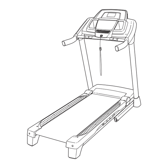
Model No. PFTL49612.1
USER'S MANUAL
Serial No.
Write the serial number in the space
above for reference.
Serial Number
Decal
QUESTIONS?
If you have questions, or if parts
are damaged or missing, DO NOT
CONTACT THE STORE; please
contact Customer Care.
IMPORTANT: Please register this
product (see the limited warranty
on the back cover of this manual)
before contacting Customer Care.
CALL TOLL-FREE:
1-888-533-1333
Mon.–Fri. 6 a.m.–6 p.m. MT
Sat. 8 a.m.–4 p.m. MT
ON THE WEB:
www.proformservice.com
CAUTION
Read all precautions and instruc-
tions in this manual before using
this equipment. Save this manual
for future reference.
Advertisement
Table of Contents

Subscribe to Our Youtube Channel
Related Manuals for Pro-Form PFTL49612.1


Summary of Contents for Pro-Form PFTL49612.1
- Page 1 Model No. PFTL49612.1 USER’S MANUAL Serial No. Write the serial number in the space above for reference. Serial Number Decal QUESTIONS? If you have questions, or if parts are damaged or missing, DO NOT CONTACT THE STORE; please contact Customer Care.
-
Page 2: Table Of Contents
TABLE OF CONTENTS WARNING DECAL PLACEMENT ............. . .2 IMPORTANT PRECAUTIONS . -
Page 3: Important Precautions
IMPORTANT PRECAUTIONS WARNING: To reduce the risk of burns, fire, electric shock, or injury to persons, read all important precautions and instructions in this manual and all warnings on your treadmill before using your treadmill. ICON assumes no responsibility for personal injury or property damage sus- tained by or through the use of this product. - Page 4 movement, may affect the accuracy of heart 24. Never insert any object into any opening on rate readings. The heart rate monitor is the treadmill. intended only as an exercise aid in determin- ing heart rate trends in general. 25. Inspect and properly tighten all parts of the treadmill regularly.
-
Page 5: Before You Begin
BEFORE YOU BEGIN Thank you for selecting the new PROFORM reading this manual, please see the front cover of this ® CT treadmill. The 425 CT treadmill offers an impres- manual. To help us assist you, please note the product sive selection of features designed to make your model number and serial number before contacting us. -
Page 6: Part Identification Chart
PART IDENTIFICATION CHART Use the drawings below to identify small parts used for assembly. The number in parentheses below each draw- ing is the key number of the part, from the PART LIST near the end of this manual. The number following the key number is the quantity used for assembly. -
Page 7: Assembly
ASSEMBLY • To hire an authorized service technician to • To identify small parts, see page 6. assemble the treadmill, call 1-800-445-2480. • Assembly requires the following tools: • Assembly requires two persons. the included hex key • Place all parts in a cleared area and remove the one Phillips screwdriver packing materials. - Page 8 2. See the inset drawing. Cut the plastic tie near the Upright Wire (87). Plastic Tie Attach a Wheel (96) to the Base (95) with a 3/8" x 2" Bolt (8) and a 3/8" Nut (10). Do not over- tighten the Nut; the Wheel must turn freely. Press a Base Cap (89) into the Base (95).
-
Page 9: Mill So That The Base (95) Is Flat On The Floor
4. Hold the Right Upright (85) against the Base (95). Be careful not to pinch the Upright Wire (87). Insert two 3/8" x 4" Screws (7) with two 3/8" Star Washers (11) and a 3/8" x 1 1/2" Screw (14) with a 3/8" Star Washer (11) into the Right Upright. - Page 10 6. Hold the Left Upright (84) against the Base (95). Insert two 3/8" x 4" Screws (7) with two 3/8" Star Washers (11) and a 3/8" x 1 1/2" Screw (14) with a 3/8" Star Washer (11) into the Left Upright.
-
Page 11: Right Upright
8. Identify the Right Upright Cover (86) and the Right Handrail (83). Slide the Right Upright Cover onto the Right Upright (85). Remove the tie from the bracket on the Right Handrail. If necessary, press the 5/16" Cage Nut (38) back Bracket into place. - Page 12 10. IMPORTANT: To avoid damaging the Crossbar (104), do not use power tools and do not overtighten the #10 x 3/4" Screws (2). Orient the Crossbar (104) as shown. Attach the Crossbar to the Handrails (82, 83) with four #10 x 3/4"...
- Page 13 12. Firmly tighten the four 5/16" x 1" Screws (3) and Console the two 5/16" x 1" Bolts (4) (only one side is Console Assembly shown). Wire With the help of a second person, hold the con- Ground sole assembly near the Right Handrail (83) and Wire the Left Handrail (not shown).
-
Page 14: Right Upright
14. Hold the Right Upright Cover (86) against the console assembly. Align the holes in the Right Upright Cover with the holes in the Right Upright (85). Attach the Right Upright Cover with two #8 x 3/4" Screws (1). Attach the Left Upright Cover (80) to the Left Upright (84) in the same way. -
Page 15: Operation And Adjustment
OPERATION AND ADJUSTMENT HOW TO CONNECT THE POWER CORD nominal 120-volt circuit capable of carrying 15 or more amps. To avoid overloading the circuit, do Use a Surge Suppressor not plug other electrical devices, except for low- power devices such as cell phone chargers, into Your treadmill, like other electronic equipment, can be the surge suppressor or into an outlet on the same circuit. - Page 16 CONSOLE DIAGRAM FEATURES OF THE CONSOLE To turn on the power, see page 17. To use the man- ual mode, see page 17. To use an onboard workout, see page 19. To use an 8-week weight-loss work- The treadmill console offers an impressive array of features designed to make your workouts more effec- out, see page 20.
-
Page 17: To Turn On Power
HOW TO TURN ON THE POWER HOW TO USE THE MANUAL MODE IMPORTANT: If the treadmill has been exposed to 1. Insert the key into the console. cold temperatures, allow it to warm to room tem- perature before turning on the power. If you do not See HOW TO TURN ON THE POWER at the left. - Page 18 5. Follow your progress with the display. When the manual mode is se- lected, the upper half of Track the display will show a Contacts track that represents 1/4 mile (400 m). As you walk or run, indicators will appear in succession around the track until the entire track appears.
-
Page 19: How To Use Onboard Workout
HOW TO USE AN ONBOARD WORKOUT The workout will continue in this way until the last segment of the profile flashes in the display and the 1. Insert the key into the console. last segment ends. The walking belt will then slow to a stop. - Page 20 HOW TO USE AN 8-WEEK WEIGHT-LOSS 4. Start the workout. WORKOUT Press the Go button, and then press the Start but- 1. Insert the key into the console. ton to start the workout. See HOW TO TURN ON THE POWER on page 17. The workout will function in the same way as an onboard workout (see step 3 on page 19).
- Page 21 HOW TO USE THE STEREO SOUND SYSTEM THE INFORMATION MODE To play music or audio books through the console’s The console features an information mode that keeps stereo speakers, you must connect your MP3 player, track of treadmill usage information. The information CD player, or other personal audio player to the con- mode also allows you to select miles or kilometers as sole through the MP3 jack.
-
Page 22: How To Fold And Move The Treadmill
HOW TO FOLD AND MOVE THE TREADMILL HOW TO FOLD THE TREADMILL HOW TO MOVE THE TREADMILL To avoid damaging the treadmill, adjust the incline Before moving the treadmill, fold it as described at the to the lowest position before you fold the treadmill. left. -
Page 23: Troubleshooting
TROUBLESHOOTING Most treadmill problems can be solved by follow- SYMPTOM: The console displays remain lit when ing the simple steps below. Find the symptom that you remove the key from the console applies, and follow the steps listed. If further assis- tance is needed, see the front cover of this manual. - Page 24 Remove the three #8 x 3/4" Screws (1) and care- If the incline system does not begin calibrating, fully pivot the Motor Hood (62) off. press the Stop button, and then press the Incline increase or decrease button again. When the incline system is calibrated, remove the key from the console.
- Page 25 SYMPTOM: The walking belt is off-center or slips b. If the walking belt slips when walked on, first when walked on remove the key and UNPLUG THE POWER CORD. Using the hex key, turn both idler roller a. If the walking belt is off-center, first remove the screws clockwise, 1/4 of a turn.
-
Page 26: Exercise Guidelines
EXERCISE GUIDELINES Burning Fat—To burn fat effectively, you must exer- WARNING: cise at a low intensity level for a sustained period of Before beginning this time. During the first few minutes of exercise, your or any exercise program, consult your physi- body uses carbohydrate calories for energy. -
Page 27: Part List
PART LIST Model No. PFTL49612.1 R0712A Key No. Qty. Description Key No. Qty. Description #8 x 3/4" Screw Right Foot Rail #10 x 3/4" Screw Frame 5/16" x 1" Screw Roller Bracket 5/16" x 1" Bolt Roller Ground Wire #8 x 1" Tek Screw... -
Page 28: Exploded Drawing
EXPLODED DRAWING A Model No. PFTL49612.1 R0712A... - Page 29 EXPLODED DRAWING B Model No. PFTL49612.1 R0712A...
- Page 30 EXPLODED DRAWING C Model No. PFTL49612.1 R0712A...
- Page 31 EXPLODED DRAWING D Model No. PFTL49612.1 R0712A...
-
Page 32: Ordering Replacement Parts
ORDERING REPLACEMENT PARTS To order replacement parts, please see the front cover of this manual. To help us assist you, be prepared to pro- vide the following information when contacting us: • the model number and serial number of the product (see the front cover of this manual) •...
Need help?
Do you have a question about the PFTL49612.1 and is the answer not in the manual?
Questions and answers
How do I reset the treadmill so the incline lowers? It is stuck.