FreeWave FGR2-PE User Manual And Reference Manual
Wireless data transceiver
Hide thumbs
Also See for FGR2-PE:
- Programming & installation manual (23 pages) ,
- User manual (91 pages)

Related Manuals for FreeWave FGR2-PE


Summary of Contents for FreeWave FGR2-PE
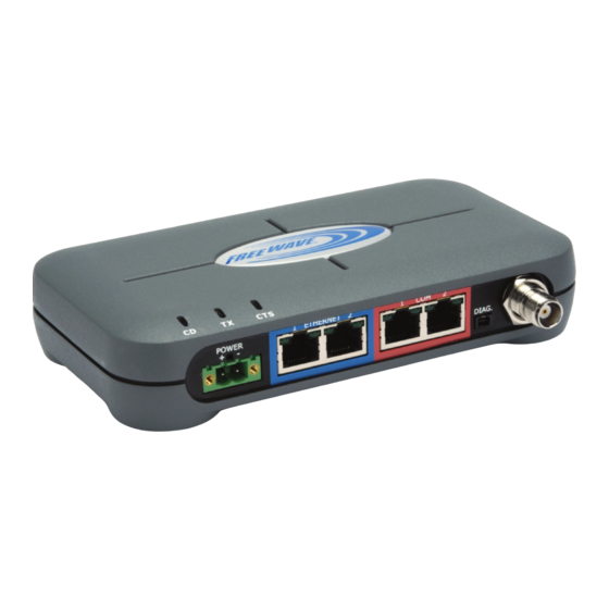
- Page 1 FGR2-PE Wireless Data Transceiver Firmware 2.22 User Manual and Reference Guide For use with Baseline Irrigation Controllers Part Number: LUM0024AB Revision: A Last Updated: 12/7/2011...
-
Page 2: Safety Information
FreeWave upon receiving a Return Material Authorization (RMA) for evaluation of Warranty Coverage. In no event will FreeWave Technologies, Inc., its suppliers, and its licensors be liable for any damages arising from the use of or inability to use this Product. This includes business interruption, loss of business information, or other loss which may arise from the use of this Product. - Page 3 Administration. Please contact FreeWave Technologies, Inc. for assistance and further information. UL Specifications The FGR2-PE transceiver is suitable for use in Class I, Division 2, Groups A, B, C, and D or non-hazardous locations only. Warning! Explosion Hazard! Substitution of components may impair suitability for Class I, Division 2.
- Page 4 This device must be operated as supplied by FreeWave Technologies, Inc.. Any changes or modifications made to the device without the express written approval of FreeWave Technologies, Inc. may void the user's authority to operate the device.
- Page 5 Firmware revision information is available in Appendix A. Discovery Server procedures are now in Appendix C. Added Windows 7 instructions for changing an IP address. Added Tool Suite procedures where appropriate throughout. Converted to the current FreeWave look and feel. LUM0024AB Rev A...
- Page 6 LUM0024AB Rev A...
-
Page 7: Table Of Contents
Table Of Contents Chapter 1: Introduction Getting to Know Your Plus-Style Transceiver Boot-Up LED Sequence Ethernet Port Conditions Error LED Conditions Com Port LED Conditions Choosing a Location for the Transceivers Choosing Point-to-Point or Point-to-MultiPoint Operation Chapter 2: Setting Up and Programming Transceivers Basic Steps to Programming Plus-Style Transceivers MultiPoint Network Considerations Powering the Transceiver... - Page 8 IP Parameter Reference Default Gateway IP Address NTP Client Enable NTP IP Address Push to Syslog Server Spanning Tree Subnet Mask Syslog Server 1 Syslog Server 2 VLAN Data ID VLAN Default Gateway VLAN IP Address VLAN Management ID VLAN Mode VLAN Subnet Mask Web Page Port (http) Chapter 4: Serial Port Settings...
- Page 9 Serial Modbus RTU Serial Parity Stop Bits TCP Client Enable TCP Client IP TCP Client Port TCP Server Enable TCP Server Inactivity Timeout TCP Server Port UDP Local IP Port UDP Power Up IP UDP Power Up Port UDP/Multicast Enable Utilize For Alarm Chapter 5: Radio Settings Radio Setup Parameter Reference Addressed Repeat...
- Page 10 Programming Point-To-Point Extended Call Book to Use Three or Four Repeaters Programming Point-to-MultiPoint Call Book Programming Point-to-MultiPoint Extended Call Book Chapter 6: Security Settings Viewing the System Log Security Parameter Reference AES Encryption Key Detach Local Ethernet Force SSL (https) MAC Filter Peer To Peer RADIUS Enable...
- Page 11 Signal Alarm Below Signal Alarm Enable Tx Rate Alarm Below Tx Rate Alarm Enable VSWR Alarm Above VSWR Alarm Enable Voltage Alarm Above Voltage Alarm Below Voltage Alarm Enable Chapter 8: Viewing Transceiver Status and Statistics Refreshing and Resetting Statistics Available Statistics Bad Packets Broadcast Packets...
- Page 12 Factory Default Settings Mechanical Drawing Appendix A: Firmware Updates Version 2.22 Version 2.21 Appendix B: Using the FreeWave TFTP Server Installing and Running the TFTP Sever TFTP Server Client Connections TFTP Control Options TFTP Server Log Moving and Renaming the TFTP Server Log...
- Page 13 Upgrading Firmware from Discovery Server Appendix D: Changing the Computer IP Address in Windows Changing the Computer IP Address in Windows XP Changing the IP Address in Windows 7 Appendix E: Object Tree for FREEWAVE-TECHNOLOGIES-MIB Object List for FREEWAVE-TECHNOLOGIES-MIB Index LUM0024AB Rev A...
- Page 14 LUM0024AB Rev A...
- Page 15 SNMP information, and security. Descriptions of each statistic that is available about the transceivers state and performance. Examples of how FreeWave transceivers can exist in a network with other transceivers. Pin outs, specifications, and other mechanical information. Information additional tools you might use when working with your Plus-style transceiver.
- Page 16 FGR2-PE Wirelss Data Transceiver The term "radio" and "transceiver" are used throughout this manual to refer to the FGR2-PE. Contacting FreeWave Technical Support For up-to-date troubleshooting information, check the Support page at www.freewave.com. FreeWave provides technical support Monday through Friday, 7:30 AM to 5:30 PM Mountain Time (GMT -7).
-
Page 17: Chapter 1: Introduction
Chapter 1: Introduction The FGR2-PE offers industrial serial and Ethernet wireless connectivity using the license-free spread spectrum for data communication over long distances. The transceiver is compatible with other FreeWave FGR plus family radios and has two Ethernet ports and two serial ports, providing the ability to transition from serial to Ethernet data communications without having to replace your wireless communications infrastructure. -
Page 18: Boot-Up Led Sequence
This port is currently non-functioning. No settings and no diagnostics are delivered to this port. All Plus-style transceivers must be programmed using Ethernet, either through the configuration Web pages or using FreeWave Tool Suite. For more information about the setup tools available, see "Configuration Tool Options" on page 16. -
Page 19: Error Led Conditions
Placement of the FreeWave transceiver is likely to have a significant impact on its performance. The key to the overall robustness of the radio link is the height of the antenna. In general, FreeWave units with a higher antenna placement will have a better communication link. In practice, the transceiver should be placed away from computers, telephones, answering machines, and other similar equipment. - Page 20 FGR2-PE Wirelss Data Transceiver to the Gateway. In a MultiPoint network, you determine the set number of times outbound packets from the Gateway or Repeater to Endpoints or other Repeaters are sent. The receiving transceiver, Endpoint or Repeater, accepts the first packet received that passes the 32 bit CRC. However, the packet is not acknowledged.
- Page 21 User Manual and Reference Guide Point-to-MultiPoint Operation LEDs Gateway Endpoint Repeater Carrier Clear to Carrier Clear to Carrier Clear to Detect Transmit Send Detect Transmit Send Detect Transmit Send Condition (CD) (Tx) (CTS) (CD) (Tx) (CTS) (CD) (Tx) (CTS) Powered, not linked Solid red Solid red Solid red...
- Page 22 LUM0024AB Rev A...
-
Page 23: Chapter 2: Setting Up And Programming Transceivers
2. Be familiar with your network and know if you have a Point-to-Point or Point-to-MultiPoint configuration. Most FreeWave networks are Point-to-MultiPoint. 3. Connect the transceiver to the configuration tool, such as Tool Suite or view the transceiver's configuration Web pages. -
Page 24: Multipoint Network Considerations
Using a dedicated power supply line is preferred. The power supply you use must provide more current than the amount of current drain listed in the "FGR2-PE Specifications" on page 99 for the voltage you are using. For example, if you are using +12 VDC, the power supply must provide above the drain that is required for transmit using +12 VDC. -
Page 25: Determining And Setting A Transceiver's Ip Address
User Manual and Reference Guide Determining and Setting a Transceiver's IP Address Before you can work with a Plus-style transceiver, you need to determine the transceiver's IP address. By default, each Plus-style transceiver's IP address is 192.168.111.100 and its password is admin. If the address has changed, if you do not know the transceiver's address, or you need to change the address, use one of the following tools: HyperTerminal using the Com 1 serial port... - Page 26 FGR2-PE Wirelss Data Transceiver 3. In the Name field, enter a descriptive name for the connection and select an icon from the Icon selection box. 4. Click OK. The Connect To dialog box displays. 5. In the Connect Using field, select the connection type to use.
- Page 27 User Manual and Reference Guide Enter the following port settings for a proper connection: Port Setting Select Bits per second 19200 Data bits Parity None Stop bits Flow control None 7. After selecting the option for each setting, click OK. The following HyperTerminal dialog box displays: 8.
- Page 28 FGR2-PE Wirelss Data Transceiver Important: To make changes to the connection properties, you must first disconnect the terminal session. To set or determine the transceiver's IP address using HyperTerminal: 1. With the HyperTerminal session from the above procedure open, connect power to the transceiver.
- Page 29 User Manual and Reference Guide 4. Enter 0 to select the IP Setup Menu to display the IP Address along with the other IP setup options: The transceiver's current IP address displays in the IP Address option. 5. To change the IP address or any other setting available here, select the number of the selection and make the changes.
-
Page 30: Using Discovery Server
You can also determine and a set the IP address of a Plus-style transceiver with a firmware version of 2.8 or higher using the FreeWave Discovery Server, a free utility available from FreeWave. Discovery Server is available on the User Manual and System Tools CD and is also available for download from www.freewave.com. -
Page 31: Resetting Transceivers To The Factory Default Settings
User Manual and Reference Guide 3. In the IP Address field, update the IP address to the address you want to assign to the transceiver. 4. In the Password field, enter the current administrator password. Transceivers running firmware version 2.14 or earlier only accept admin as the valid password. Transceiver's running a later version of firmware accept any password up to 7 characters long. -
Page 32: Configuration Tool Options
FGR2-PE Wirelss Data Transceiver 4. Enter default at the prompt and press Enter. The transceiver reboots, and all of the transceiver settings are reset to the factory defaults. Configuration Tool Options After you have determined the Ethernet address of your Plus-style transceiver, you can use either Tool Suite or the configuration Web pages accessed through any Web browser for general programming and setup. - Page 33 Set the SNMP management features of the transceiver. The transceiver supports SNMP versions 1, 2, and 3. All of the SNMP-manageable objects for FreeWave's radios are contained in a single MIB file: FREEWAVE-TECHNOLOGIES-MIB. This file is available from FreeWave upon request. For more information, "SNMP Settings" on page...
-
Page 34: Reading Plus-Style Transceivers In Tool Suite
FGR2-PE Wirelss Data Transceiver Page Used To Set FreeWave Redundant Master System units only. For details about these settings, see the Redundant Master System User Manual Adden- dum. Diagnostics View the signal level, noise level, signal-to-noise delta, and receive rate for each frequency available to the transceiver. -
Page 35: Accessing Configuration Web Pages
User Manual and Reference Guide Accessing Configuration Web Pages Each Plus-style transceiver has a built in Web interface that you can use to program its settings. To access the Web interface, you must have a Web browser installed on your computer. 1. -
Page 36: Providing Site Information
FGR2-PE Wirelss Data Transceiver Any change made in the configuration Web pages that is not yet saved is highlighted in yellow. This highlight indicates that you need to click Save/Apply before navigating away from the page, or the changes will be lost. -
Page 37: Using The Multipoint Gateway To Change All Connected Transceivers
User Manual and Reference Guide 2. In the Pages menu on the left side, click Tools to display the Tools page. 3. In the Change Site Information section of the page, provide any of the following information: Field Description Site Name Enter any text up to 25 characters that helps to identify the transceiver. -
Page 38: Creating User Logins
FGR2-PE Wirelss Data Transceiver Important: Changes made to the settings on this page can cause the radios to lose communication with the Gateway and/or MultiPoint Repeaters. Use caution when making global changes. Security page - All settings on the Security page can be part of a Global Change. -
Page 39: Adding And Deleting Users
User Manual and Reference Guide Note: You cannot change the group assigned to the admin user. The admin user always has Full Access to all pages. To edit user group rights using Tool Suite: 1. Access the transceiver's settings in Tool Suite. For more information, see "Reading Plus-Style Transceivers in Tool Suite"... -
Page 40: Changing User Passwords
The Plus-style transceivers share a common firmware upgrade platform and process using the FreeWave TFTP Server and a FreeWave-supplied firmware upgrade file. This section details the step-by-step process of upgrading firmware either locally (directly connected to the transceiver via an Ethernet cable) or over-the-air (OTA). -
Page 41: Before You Get Started Upgrading Firmware Using The Tftp Server
Configuring the TFTP Server The FreeWave TFTP Server enables the transfer of the firmware file from your computer to the Plus-style transceiver. After you download the FreeWave TFTP Server program, run the installer to gain access to the executable program, fwTFTP.exe. -
Page 42: Upgrading Firmware Using The Web Configuration Pages
Firmware Using the Web Configuration Pages" on page 26. Upgrading Firmware Using the Web Configuration Pages After you have configured the FreeWave TFTP Server, you are ready to complete the firmware upgrade using the transceiver's configuration Web pages. 1. Access the radio's configuration Web pages. -
Page 43: Upgrading Plus-Style Firmware Globally
User Manual and Reference Guide If the firmware file is being uploaded to the transceiver, there is a new entry in the FreeWave TFTP Server window, with a progress bar. Over a local connection, for example connected directly from computer to transceiver using an Ethernet cable, the upgrade can take less than 30 seconds. -
Page 44: Verifying Firmware Upgrades
Common Firmware Upgrade Issues and Solutions ”File Not Found” in either the configuration Web page or the FreeWave TFTP server Check the filename of the firmware upgrade file. The file name must be typed exactly as the file is named. If you have checked the name and are still unsuccessful, check the extension of the file. - Page 45 If the firmware upgrade is being done over-the-air, it can take a significant amount of time to complete the file transfer. This time can be extended if the quality of the link is poor. FreeWave recommends only attempting an over-the-air firmware upgrade with links that are stable and of high quality.
- Page 46 LUM0024AB Rev A...
-
Page 47: Chapter 3: Ip And Network Communication Settings
Chapter 3: IP and Network Communication Settings The parameters on the IP Setup tab or IP Setup configuration Web page are typically set by a network administrator. These are the parameters that set the Ethernet address and other communications for the transceiver. -
Page 48: Default Gateway
FGR2-PE Wirelss Data Transceiver Network Type: Point-to-Point, Point-to-MultiPoint, or Both Default Setting: The factory default setting for the parameter. Options: The options to which the parameter can be set. Description: A description of what the parameter is and how it applies to the transceiver in your network. -
Page 49: Ntp Client Enable
User Manual and Reference Guide NTP Client Enable Web Parameter Enable check box in the NTP Client section of the IP Setup page. Network Type: Both Default Setting: Disabled Options: Disabled, Enabled Description: Enables the Network Time Protocol (NTP) client on the transceiver. The transceiver checks with the NTP Server specified in the NTP Client IP Address parameter and sets its internal clock to the time and date specified by the NTP server. -
Page 50: Subnet Mask
Spanning Tree Protocol does use transceiver bandwidth, as any Spanning Tree transceivers are constantly communicating their network “location.” FreeWave recommends leaving Spanning Tree disabled, unless the Spanning Tree Protocol is required in your application. Subnet Mask Web Parameter: Subnet Mask in the LAN Network Interface Configuration section of the... -
Page 51: Vlan Data Id
User Manual and Reference Guide VLAN Data ID Web Page: Data VLAN ID in the VLAN Configuration (Data) section of the IP Setup page. Network Type: Both Default Setting: Options: Any valid VLAN ID between 1 and 4095. Description: Data using this VLAN ID is allowed to come into or be sent out of the transceiver’s local Ethernet port and is allowed to access the serial ports via the terminal server. -
Page 52: Vlan Mode
Description: Computers and devices using the VLAN ID entered here are able to access the transceiver’s Setup pages, receive SNMP information, send SNMP commands, and view the transceiver in the FreeWave Discovery Server. VLAN Mode Web Parameter: Mode in the VLAN Configuration (Data) section of the IP Setup page. - Page 53 User Manual and Reference Guide Description: Use this setting to change the assigned port for the configuration Web pages. The default setting is port 80, the standard Web page port. If this setting is changed from port 80, the proper port number must be included when accessing the Setup pages.
- Page 54 LUM0024AB Rev A...
-
Page 55: Chapter 4: Serial Port Settings
Chapter 4: Serial Port Settings Use the settings on the Serial Setup tab or page to set the serial ports on the transceiver. The ports are labeled 1 and 2 on the physical transceiver. See the transceiver illustration in "Getting to Know Your Plus-Style Transceiver"... -
Page 56: Disabling Serial Ports
FGR2-PE Wirelss Data Transceiver 4. Select Enabled in one of the following fields to enable that mode. If all the fields are set to Disabled, then the port is disabled. TCP Server Enable - Sets the port as a TCP terminal server. -
Page 57: Using The Serial Port As An Alarm Client
User Manual and Reference Guide TCP Server Enable TCP Client Enable UDP/Multicast Enable 5. Select a Tool Suite program option to send the changes to the transceiver. For more information about using Tool Suite, see the Tool Suite User Manual available on the User Manual and System Tools CD or by selecting File >... -
Page 58: Ethernet (Rx And Tx)
FGR2-PE Wirelss Data Transceiver Ethernet (Rx and Tx) The amount of data received (rx) and transmitted (tx) from the terminal server to the port. Received data indicates data received on the transceiver from the serial port. Transmitted data indicates data sent from the transceiver out the serial port. -
Page 59: Alarm Retry Limit (Attempts)
User Manual and Reference Guide Alarm Retry Limit (Attempts) Web Parameter: Alarm Retry Limit in the TCP Server Settings of the Serial Setup page. Network Type: Both Default Setting: Options: Any number of retry attempts. There is no limit. Description: The number of times the transceiver attempts to create an outgoing TCP connection when acting as an alarm client (when the Utilize For Alarm parameter is set to Enabled). -
Page 60: Multicast Port
FGR2-PE Wirelss Data Transceiver In the configuration Web pages, enter the IP address in the field to the left of the colon. Enter the port number in the field to the right of the colon. Multicast Port Web Parameter: Multicast Address & Port in the Multicast Settings section of the Serial Setup page. -
Page 61: Serial Data Bits
User Manual and Reference Guide transmission of data. Description: Controls the function of the CD line on the serial port. Serial Data Bits Web Parameter: Data Bits in the Serial Settings section of the Serial Support page. Network Type: Both Default Setting: Options: 5, 6, 7, 8... -
Page 62: Serial Parity
FGR2-PE Wirelss Data Transceiver Setting this option is recommended for any serial data that consist of many small packets of data. Serial Parity Web Parameter: Parity in the Serial Settings section of the Serial Setup page. Network Type: Both Default Setting:... -
Page 63: Tcp Client Ip
User Manual and Reference Guide TCP Client IP Web Parameter IP Address & Port in the TCP Client Settings section of the Serial Setup page. Network Type: Both Default Setting: 0.0.0.0 Options: Any valid IP address. Description: The IP address the transceiver creates a connection to on boot-up, when the transceiver is set to TCP Client mode. -
Page 64: Tcp Server Port
Note: In some RTUs, after the RTU is connected to the transceiver as a client, the RTU does not properly disconnect the TCP session. To help overcome this potential behavior of some RTUs, FreeWave recommends setting Inactivity Timeout to 10. -
Page 65: Udp Power Up Port
User Manual and Reference Guide UDP Power Up Port Web Parameter Power UP Dest. IP & Port in the UDP Settings section of the Serial Setup page. Network Type: Both Default Setting: 0000 Options: Any valid port number between 0 and 65535. Description: The port used if the serial port is set to UDP mode. -
Page 66: Utilize For Alarm
FGR2-PE Wirelss Data Transceiver In a MultiPoint Gateway radio, selecting multicast causes the transceiver to act as an IP Multicast Sender on the Multicast address and port. Utilize For Alarm Web Parameter: Enable Alarm Client check box on the Serial Setup configuration Web page. -
Page 67: Chapter 5: Radio Settings
Chapter 5: Radio Settings Use the settings on the Radio Setup tab or Radio Setup configuration Web page to set the general functioning of the transceiver. Within Radio Setup, you can set the following parameter types: Operation Mode - Designates the mode the transceiver uses to communicate and the network type. -
Page 68: Radio Setup Parameter Reference
FGR2-PE Wirelss Data Transceiver Radio Setup Parameter Reference This section contains the following information as it applies to the radio setup parameters that you can set for the transceivers described in this document. parameter name (as you see it in Tool Suite) Web Parameter: The name of the field as it appears in the configuration Web pages. -
Page 69: Broadcast Repeat In Multipoint Networks With Repeaters
User Manual and Reference Guide Network Type: MultiPoint Default Setting: Options: Any number between 0 and 9. Description: In a MultiPoint network, Endpoints do not acknowledge transmissions from the Gateway that are addressed for broadcast MAC addresses. If Endpoints did acknowledge all broadcast MAC address transmissions, in a large network the Gateway would soon become overwhelmed with acknowledgments from the Endpoints. -
Page 70: Frequency Key
These hopping patterns minimize the interference with other FreeWave transceivers operating in the area. For example, if there were 10 pairs of FreeWave transceivers operating on different networks in close proximity, setting a different Frequency Key value for each pair reduces the chance that transceivers hop to the same frequency at the same time. -
Page 71: Master Tx Beacon
Without having the serial numbers in the Call Book, an Endpoint may establish communications with different Gateways, though not at the same time. This is useful in mobile MultiPoint applications. FreeWave recommends a Network ID of four characters. For example, the last four digits of the Gateway's serial number. Master Tx Beacon Note: This setting needs to be the same in every Gateway, Repeater, and Endpoint. - Page 72 The following table defines the minimum packet size (in bytes) by way of charting the Min Packet Size setting versus the RF Data Rate setting. Using the default settings, the actual minimum packet size for the transceivers, in bytes, is 21 in the FGR2-PE. Minimum Packet Size Definition...
- Page 73 User Manual and Reference Guide Maximum Packet Size Definition with RF Data Rate of 154 kbps (in bytes) Max Setting (blank area = not recommended) Setting Referencing the default settings, the Gateway transmits up to 213 bytes on every hop. If fewer than 213 bytes are transmitted by the Gateway, the balance is allocated to the Endpoint's transmission, plus the quantity in the Min Packet Size setting.
-
Page 74: Modem Mode
Description: The Network Type and Modem Mode options designate the method FreeWave transceivers use to communicate with each other. FreeWave Ethernet transceivers operate in a Gateway-to-Endpoint configuration. Before the transceivers can operate together, they must be set up to properly communicate. -
Page 75: Network Type
Endpoint may communicate with its Gateway through one or more Repeaters. Point-to-Point Repeater FreeWave allows the use of up to four Repeaters in a Point-to-Point (Single Radio Repeater) communications link, significantly extending the operating range. When designated as a Point-to-Point Repeater, a transceiver behaves as a pass-through link. -
Page 76: Repeaters
Many advanced features of the Plus-style transceiver are restricted in networks where the Repeaters parameter is Enabled. For best operation, FreeWave does not recommend the use of single-radio Repeaters. Retry Timeout Note: While intended primarily for MultiPoint networks, the Retry Time Out parameter may also be modified in Point-to-Point networks. -
Page 77: Rf Data Rate
Gateway or Endpoint(s). As the link gets weaker, a lower setting allows a poor link to break in search of a different link. Note: FreeWave recommends setting the Retry Time Out to 20 in areas where several FreeWave networks exist. This setting allows Endpoints and Repeaters to drop the connection if the link becomes too weak, while at the same time prevents errant disconnects due to interference from neighboring networks. -
Page 78: Slave Connect Odds
FGR2-PE Wirelss Data Transceiver higher the Slave Connect Odds setting, the more persistent that Endpoint will be in attempting to acquire the Gateway’s connection. This setting is a chance out of a total of 15. For example, a setting of 1 means the radio has a 1 in 15 chance (6.66…%), and a setting of 9 means a 9 in 15 chance (60%). -
Page 79: Subnet Id Example
User Manual and Reference Guide F, an Endpoint or Repeater connects with the first Repeater or Gateway that it hears with the same Network ID. There are scenarios, however, where communications need to be forced to follow a specific path. Subnet ID is particularly helpful to force two Repeaters in the same network to operate in series rather than in parallel, or, if desired, to force Endpoints to communicate to a specific Repeater for load balancing purposes. - Page 80 FGR2-PE Wirelss Data Transceiver The following table shows the subnet IDs for the above example: Subnet Subnet Transceiver (RX) ID (TX) Other Information Gateway The Gateway uses 0,0. Gateway The Subnet ID (TX) value may be set in the Gateway.
-
Page 81: Transmit Power
User Manual and Reference Guide Transmit Power Web Parameter: Transmit Power in the Transmission Characteristics section of the Radio Setup page. Network Type: Both Default Setting: Options: Any number between 0 and 10. Description: Sets the output power of the transceiver. A setting of 10 is approximately 1 W of output power in a Plus-style radio. -
Page 82: About The Call Book
3. The Gateway must be programmed to call the Endpoint (Entry to Call option). The Call Book allows you to incorporate up to 10 FreeWave transceivers, designate 1 to 4 Repeaters to use with each transceiver, and designate which Endpoint the Gateway calls. To set the Entry to Call option, select the number in the Entry to Call field, select All to direct the Gateway to call all Endpoints. -
Page 83: Programming Point-To-Multipoint Call Book
Endpoint. Programming Point-to-MultiPoint Call Book Note: FreeWave recommends using the Network ID feature instead of the Call Book in a MultiPoint network. If the Network ID feature is used in a MultiPoint network, no entries are needed in the Call Book of any of the transceivers. -
Page 84: Programming Point-To-Multipoint Extended Call Book
FGR2-PE Wirelss Data Transceiver Number 884-1111 884-2222 000-0000 At times, you may want to force an Endpoint to go through a specific MultiPoint Repeater. In this scenario, the Endpoint's Call Book should contain only the serial number for that Repeater as the entry on line 0. - Page 85 User Manual and Reference Guide To set the Call Book in HyperTerminal: 1. Select (2) Call Book from the main Setup menu to display the following window: 2. Enter the number or letter associated with the option you want to select. 3.
- Page 86 LUM0024AB Rev A...
-
Page 87: Chapter 6: Security Settings
Chapter 6: Security Settings Use the settings on the Security tab or Security configuration Web page to define elements that further enhance the security of your network and the data being passed within it. Typically, a system administrator addresses security parameters. Within the Security parameters, you can set the following security features: Remote Authentication Dial In Service (RADIUS) server information - Requires authentication from Endpoints and MultiPoint Repeaters before being able to send or receive Ethernet data. -
Page 88: Security Parameter Reference
The parameters are listed in alphabetical order by their Tool Suite field name. AES Encryption Key Note: The encryption key must be the same on every transceiver in the FreeWave network. Web Parameter Key in the AES Encryption section of the Security page. -
Page 89: Detach Local Ethernet
User Manual and Reference Guide Options: Any free form text up to 16 characters long. Description: A user-defined encryption key for the 128-bit AES encryption. 128-bit AES encryption is always enabled, although the encryption key may be blank. When changing the AES encryption key globally, first make the change on the MultiPoint Gateway. -
Page 90: Peer To Peer
FGR2-PE Wirelss Data Transceiver Entering a hardware (MAC) address in the MAC Filter field and clicking Add puts that MAC address into the MAC Filter list. Selecting a MAC address in the MAC Filter list and clicking Delete removes that address from the list. -
Page 91: Radius Ip Address
User Manual and Reference Guide neither sent via the Ethernet port, nor via the radio link. RADIUS IP Address Note: This option is controlled from the Gateway only. It has no functionality on Endpoints or MultiPoint Repeaters. Web Parameter: RADIUS IP Address in the RADIUS Authentication Configuration section of the Security page. - Page 92 FGR2-PE Wirelss Data Transceiver Security page. Network Type: Both Default Setting: Blank Options: Any free form text. Description: The RADIUS password for the transceiver. An entry for the transceiver should be created in the RADIUS server’s “Users” file. The transceiver always reports its serial number, minus any hyphens, as its username.
-
Page 93: Chapter 7: Snmp Settings
The basic object tree structure and a description of each element available in that file is available in "Object Tree for FREEWAVE-TECHNOLOGIES-MIB" on page 125. The file is available from FreeWave upon request. -
Page 94: Auth Method
FGR2-PE Wirelss Data Transceiver Options: The options to which the parameter can be set. Description: A description of what the parameter is and how it applies to the transceiver in your network. The parameters are listed in alphabetical order by their Tool Suite field name. -
Page 95: Privacy Password (V3)
User Manual and Reference Guide Privacy Password (v3) Note: This option is only available when v3 is selected as the SNMP Version. Web Parameter: Privacy Password in the SNMP Agent Configuration section of the SNMP page. Network Type: Both Default Setting: Blank Options: Any free form text. -
Page 96: Trap Manager Ip
FGR2-PE Wirelss Data Transceiver Trap Manager IP Web Parameter: Trap Manager 1 IP and Trap Manager 2 IP in the SNMP Trap Configuration section of the SNMP page. Network Type: Both Default Setting: 0.0.0.0 Options: Any valid IP address. Description: The IP addresses of the authorized SNMP Trap Managers. DNS names are not accepted. -
Page 97: Delta Alarm Enable
User Manual and Reference Guide your network. The parameters are listed in alphabetical order by their Tool Suite field name. Delta Alarm Enable Web Parameter: S-N Delta Enable check box in the SNMP Trap Limits section of the SNMP page. Network Type: Both Default Setting: Disabled... -
Page 98: Noise Alarm Enable
FGR2-PE Wirelss Data Transceiver Options: Any whole, negative number between -100 and -70 db, in increments of 5. Description: If the Noise Alarm Enable option is set to Enabled, a trap condition occurs if the Noise Level goes above the value in this parameter. -
Page 99: Signal Alarm Enable
User Manual and Reference Guide Signal Alarm Enable Web Parameter: Signal Enable check box in the SNMP Trap Limits section of the SNMP page. Network Type: Both Default Setting: Disabled Options: Disabled, Enabled Description: Enables a trap for the Signal Level the transceiver reports. The trap condition is present based on the settings in the Signal Alarm Below parameter. -
Page 100: Vswr Alarm Enable
FGR2-PE Wirelss Data Transceiver VSWR Alarm Enable Web Parameter: Reflected Power Enable check box in the SNMP Trap Limits section of the SNMP page. Network Type: Both Default Setting: Disabled Options: Disabled, Enabled Description: Enables a trap for the reflected power of the transceiver. The trap condition is present based on the settings in the VSWR Alarm Above parameter. -
Page 101: Chapter 8: Viewing Transceiver Status And Statistics
Chapter 8: Viewing Transceiver Status and Statistics A Plus-style transceiver's status and statistics are available on the Status page in the configuration Web pages. The parameters available on this page are all view-only regardless if you are logged in as an administrator or as a guest. -
Page 102: Refreshing And Resetting Statistics
The current version number of the firmware revision installed on the transceiver. For information about upgrading the firmware, see "Upgrading Plus-Style Transceiver Firmware Using TFTP Server" on page 24 Hardware Version For internal FreeWave use. When speaking with a Technical Support representative, they may ask for this information. Noise The level of background noise and interference at this transceiver. -
Page 103: Notes
Note: This statistic is only valid in a MultiPoint network. The percentage of packets successfully received by this transceiver. This statistic displays 0.00% in a MultiPoint Gateway. FreeWave recommends a minimum 75% success rate or proper transceiver operation. RX Throughput The throughput of data being received over the radio link within the last 1 second. -
Page 104: Signal
Temperature The current operating temperature of the transceiver in both degrees Celsius and degrees Fahrenheit. FreeWave transceivers must be in a the temperature range of -40° to +75° C TX Success Rate Note: This statistic is only valid on MultiPoint Endpoint radios. -
Page 105: Upstream Noise
User Manual and Reference Guide On the Gateway, this statistic shows a packet that is addressed to a device the Gateway believes is on its wireless network, the Gateway has exhausted all of its packet retries, and the Gateway never received any acknowledgements for that packet. Reasons for this include the following: The destination address is not actually in the wireless network. - Page 106 LUM0024AB Rev A...
-
Page 107: Chapter 9: Data Communication Link Examples
Chapter 9: Data Communication Link Examples A FreeWave transceivers’ versatility allows data communication links to be established using a variety of different configurations. The example below shows the most common and straight forward link; a Gateway communicating to a Endpoint in a Point-to-Point link. - Page 108 FGR2-PE Wirelss Data Transceiver The example below shows a configuration where a Gateway routinely calls a number of Endpoints at different times. The Gateway is communicating with a transceiver designated as an Endpoint/Repeater that is connected to a remote device. Since this device is placed in an elevated location, the transceiver may also be used as a Repeater when it is not used as an Endpoint.
- Page 109 User Manual and Reference Guide The last example is a Point-to-MultiPoint network which uses one of the sites as an Endpoint/Repeater. This network functions in the same manner as a standard MultiPoint network with Repeaters. However, the number of transceivers may be reduced with the use of the MultiPoint Endpoint/Repeater feature. LUM0024AB Rev A...
- Page 110 LUM0024AB Rev A...
-
Page 111: Chapter 10: Additional Transceiver Information
The most common operation of RS485 is a two-wire comprised of a 120 ohm impedance single twisted pair. In this system the loading of the FreeWave transceiver is as described above which allows up to 256 1/8 unit load units on the bus. Maximum line length is also 4,000 feet with a third wire required for data common. The FreeWave transceiver checks the line to be certain no other device is transmitting before enabling the line driver for data transmission. -
Page 112: Rs422 And Rs485 Full Duplex Pinouts
Short 7 and 8 Signal Ground RJ45 to DB9 Cable Use the cable above to connect a Com port on the FGR2-PE to a serial device. The pin assignments are provided in the sections below. Com1 and Com2 RJ45 Pin Assignments... -
Page 113: Db9 Connector Pin Assignments
User Manual and Reference Guide Assignment Signal Definition Data Set Ready Output Always high when the radio is powered from the Phoenix power connector. Indicates power is on to the transceiver. Carrier Detect Output Used to show an RF connection between transceivers. - Page 114 FGR2-PE Wirelss Data Transceiver Assignment Signal Definition Request to Send Input The transceiver does not recognize RTS for flow control. RTS is used as a control line in RTS/CTS mode. Clear to Send Output This signal is used to tell the system device connected to the transceiver that the transceiver is ready to receive data.
-
Page 115: Fgr2-Pe Specifications
User Manual and Reference Guide FGR2-PE Specifications Specification Frequency Range 902 to 928 MHz (FHSS) Transmitter Output Power 5 mW to 1 W Range—Line-of-Sight Point-to-Point: 60 miles, Point-to-Multipoint: 60 miles Modulation 2 level GFSK Occupied Bandwidth 230.4 kHz Hopping Patterns... - Page 116 FGR2-PE Wirelss Data Transceiver Specification Operating Temperature -40° C to +75° C (-40° F to +167° F) Dimensions 6.8 in L x 3.8 in W x 1.4 in H (17.3 cm L x 9.6 cm W x 3.5 cm H) Weight 1.3 lbs (0.6 kg)
-
Page 117: Factory Default Settings
User Manual and Reference Guide Factory Default Settings The Plus-style transceivers ship from the factory with the following default settings: Parameter Default Setting Serial Setup (1 and 2) Parameter Mode TCP Server TCP Server Port Setup 1: 7000 Setup 2: 7001 TCP Server Alarm Disabled TCP Server Alarm IP &... - Page 118 FGR2-PE Wirelss Data Transceiver Parameter Default Setting Default Gateway 192.168.111.1 Web Page Port Spanning Tree Disabled Mode Disabled IP Address (VLAN Configuration) 192.168.111.100 Management VLAN ID Data VLAN ID NTP Client Enable Disabled NTP Client IP Address 0.0.0.0 Syslog Server Push To Server...
- Page 119 User Manual and Reference Guide Parameter Default Setting Repeaters Disabled Subnet ID (RX) Subnet ID (TX) Security Parameter Enable RADIUS Disabled RADIUS IP Address Blank RADIUS Port Number 1812 Shared Secret Blank User-Password Blank AES Encryption Key Blank MAC Filter Blank Detach Local Eth Disabled...
- Page 120 FGR2-PE Wirelss Data Transceiver Parameter Default Setting Signal Alarm Below: -90 Noise Alarm Above: -100 RMS Parameter Mode Disabled Paired Radio IP 0.0.0.0 Min Fault Time (Seconds) Voltage Alarm Above: 30 Alarm Below: 6 Reflected Power Alarm Above: 2 Users Parameter...
- Page 121 User Manual and Reference Guide Parameter Default Setting Level 2: No Access Level 3: No Access Tools Parameter Site Name Blank Site Contact Blank System Name Blank Notes Blank Global Change Capability Disabled Address of TFTP Server Blank File Name Blank LUM0024AB Rev A...
-
Page 122: Mechanical Drawing
FGR2-PE Wirelss Data Transceiver Mechanical Drawing LUM0024AB Rev A... -
Page 123: Appendix A: Firmware Updates
The latest firmware versions are available on the FreeWave Web site at www.freewave.com. You can also view the latest firmware available for most models in Tool Suite. The sections below describe the updates and known limitations in each firmware revision for the Plus-style transceivers. -
Page 124: Version 2.21
FGR2-PE Wirelss Data Transceiver FreeWave now supports only the following versions: SSLv3 256 bits AES256-SHA SSLv3 128 bits AES128-SHA SSLv3 168 bits DES-CBC3-SHA SSLv3 128 bits RC4-SHA SSLv3 128 bits RC4-MD5 TLSv1 256 bits AES256-SHA TLSv1 128 bits AES128-SHA TLSv1 168 bits DES-CBC3-SHA... - Page 125 User Manual and Reference Guide Ack packet optimizations. Connect/Disconnect with data. Changed VLAN operation. Added RMS page and functionality. Added diagnostics values (Broadcast packets, Radio Addressed Packets, Peer to Peer packets, Radio Parse error, RX and TX throughput). Changed Radio Connect Odds functionality. Added Peer-to-Peer security feature.
- Page 126 LUM0024AB Rev A...
-
Page 127: Appendix B: Using The Freewave Tftp Server
Appendix B: Using the FreeWave TFTP Server TFTP Server enables the transfer of the files from your computer to the Plus-style transceivers, specifically, the transfer of firmware files for firmware upgrades. For more information about upgrading the firmware on your Plus-style transceivers, see "Upgrading Plus-Style Transceiver Firmware Using TFTP Server"... -
Page 128: Installing And Running The Tftp Sever
If you accept the default installation directory, the program is installed in C:\Program Files\FreeWave Technologies\fwTFTP. 3. From the Windows Start menu, select All Programs > FreeWave Technologies >fwTFTP > fwTFTP.exe to open the application. All existing client connections are dropped when the program closes. The log file is not erased when the program is restarted. -
Page 129: Tftp Control Options
Moving and Renaming the TFTP Server Log By default, the TFTP Server log file is created in the FreeWave TFTP Server program folder and is named “Log.csv”. You can move the file or change the file's name using the configuration options in the TFT Server window. -
Page 130: Clearing The Tftp Server File
The root folder is where TFTP clients access files. By default, the root folder is named Root and is created under the FreeWave TFTP Server folder in the Windows Program Files folder. You can direct the root folder to any other folder or drive on your computer. -
Page 131: Appendix C: Using The Discovery Server
Appendix C: Using the Discovery Server You can use the FreeWave Discovery Server to determine and set a transceiver's IP address and other Ethernet communication settings. The Discovery Server is a free utility available from FreeWave and is available on the User Manual and System Tools CD and is also available for download from www.freewave.com. -
Page 132: Adding Transceivers Manually To The Discovery Server List
FGR2-PE Wirelss Data Transceiver Note: Depending on your IT department’s policies, broadcasts may be blocked through any routers, so the transceiver may need to be on the same LAN segment as the computer running the Discovery Server. The Discovery Server shows the serial number, radio name (if assigned), IP address, subnet mask, default gateway, Web port, and firmware version for each discovered transceiver in the network. -
Page 133: Accessing A Transceiver's Web Page From Discovery Server
User Manual and Reference Guide If the password is correct, the radio reboots and applies the requested changes. Otherwise, the radio ignores the change request. Accessing a Transceiver's Web Page from Discovery Server Each Plus-style transceiver also has a set of configuration Web pages where you can set IP address, serial port, and other configuration settings. -
Page 134: Working With Network Files In Discovery Server
FGR2-PE Wirelss Data Transceiver Upstream Margin unAcked Packets % Rx Distance % Tx # Disconnects VSWR (Reflected Power), Connected To Temp You can also view these radio statistics in the Status page in the transceiver's configuration Web pages. 1. Open the Discovery Server application. -
Page 135: Exporting Transceiver Information From Discovery Server
3. Name the file and click Save to save the data in .csv format. Upgrading Firmware from Discovery Server The Mass Firmware Upgrade option available in the Mass Options menu in Discovery Server is for FreeWave internal use only. LUM0024AB Rev A... - Page 136 LUM0024AB Rev A...
-
Page 137: Appendix D: Changing The Computer Ip Address In Windows
Appendix D: Changing the Computer IP Address in Windows The following sections detail how to change the IP address of your computer in Windows XP and in Windows 7.0. Changing the Computer IP Address in Windows XP The following instructions are for Windows XP. 1. -
Page 138: Changing The Ip Address In Windows 7
FGR2-PE Wirelss Data Transceiver 5. Select the Use the following IP address radio button, and enter an appropriate IP address in the IP Address field. 6. Press Tab and Windows XP enters a Subnet Mask of 255.255.255.0 automatically. 7. Click OK to accept your changes and OK again to close the Local Area Connection Properties window. - Page 139 User Manual and Reference Guide 5. Click Properties to display the Local Area Connection Properties window. 6. Select Internet Protocol Version 4 (TCP/IPv4) in the list and click Properties. If you use IPv6 IP addresses, select Internet Protocol Version 6 (TCP/IPv6) and click Properties. IPv6 succeeds IPv4 and provides additional IP addresses when all the addresses in the IPv4 protocol.
- Page 140 FGR2-PE Wirelss Data Transceiver 9. Click OK to accept your changes and OK again to close the Local Area Connection Properties window. LUM0024AB Rev A...
-
Page 141: Appendix E: Object Tree For Freewave-Technologies-Mib
Appendix E: Object Tree for FREEWAVE- TECHNOLOGIES-MIB This appendix includes a visual representation of the FREEWAVE-TECHNOLOGIES-MIB file and also includes a description of each object in the MIB file. The MIB file is available from FreeWave Technologies, Inc.by request. LUM0024AB Rev A... - Page 142 FGR2-PE Wirelss Data Transceiver LUM0024AB Rev A...
- Page 143 User Manual and Reference Guide (continued) LUM0024AB Rev A...
-
Page 144: Object List For Freewave-Technologies-Mib
FGR2-PE Wirelss Data Transceiver Object List for FREEWAVE-TECHNOLOGIES-MIB Object Description Access Syntax fwtPlusModemIndex An index used to identify a specific radio Unsigned32 modem within the system. Accessible fwtPlusModemSignal The received signal level for this radio Read Only Integer 32 modem, in dBm. - Page 145 User Manual and Reference Guide Object Description Access Syntax fwtPlusModemPacketRxCount The Number of ethernet packets the radio Read Only Unsigned32 has received over its RF link. fwtPlusModemPacketTxCount The Number of ethernet packets the radio Read Only Unsigned32 has sent over its RF link. fwtPlusModemDroppedCount The Number of ethernet packets the radio Read Only...
- Page 146 FGR2-PE Wirelss Data Transceiver Object Description Access Syntax fwtPlusModemRxSubnetID A numerical ID that radios use to decide Read/Write Unsigned32 ( which subnet they are allowed to link to. 0..15 ) fwtPlusModemTxSubnetID A numerical ID that radios use to decide Read/Write Unsigned32 ( which subnet they will transmit on.
- Page 147 User Manual and Reference Guide Group Object Description Objects fwtPlusModemReflectedPowerBad This notification is generated fwtPlusModemReflectedPower when the reflected power for a fwtPlusModemVendorString radio modem goes out of fwtPlusModemSystemName specification. fwtPlusModemSNDeltaBad This notification is generated fwtPlusModemSNDelta when the Signal to Noise fwtPlusModemVendorString delta for a radio modem goes fwtPlusModemSystemName...
- Page 148 FGR2-PE Wirelss Data Transceiver Group Object Description Objects fwtPlusModemStatusGroup A collection of objects fwtPlusModemSignal concerned with the current fwtPlusModemNoise status of a radio modem. fwtPlusModemSupplyVoltage fwtPlusModemRxRate fwtPlusModemReflectedPower fwtPlusModemTemperature fwtPlusModemRange fwtPlusModemTxRate fwtPlusModemSNDelta fwtPlusModemVendorString fwtPlusModemConnectedTo fwtPlusModemUpstreamSignal fwtPlusModemUpstreamNoise fwtPlusModemDisconnectCount fwtPlusModemPacketRxCount fwtPlusModemPacketTxCount fwtPlusModemPacketDroppedCount fwtPlusModemPacketBadCount...
- Page 149 User Manual and Reference Guide Group Object Description Objects fwtPlusModemControlGroup A collection of objects fwtPlusModemNetworkMode concerned with the current fwtPlusModemMode status of a radio modem. fwtPlusModemFrequencyKey fwtPlusModemMinPacketSize fwtPlusModemMaxPacketSize fwtPlusModemTxPower fwtPlusModemRetryTimeout fwtPlusModemRFDataRate fwtPlusModemBroadcastRepeat fwtPlusModemNetworkID fwtPlusModemRepeaters fwtPlusModemRxSubnetID fwtPlusModemTxSubnetID fwtPlusModemReboot fwtPlusModemMaxSlaveRetry fwtPlusModemSystemName fwtPlusModemFreqZoneDescr fwtPlusModemFreqZoneEnabled LUM0024AB Rev A...
- Page 150 LUM0024AB Rev A...
-
Page 151: Index
User Manual and Reference Guide Auth Method, defined Index Auth Password (v3), defined Bad Packets, defined Addressed Repeat, defined Baud Rate, defined AES Encryption Key, defined boot-up sequence LEDs Alarm IP & Port, defined Broadcast Packets, defined Alarm Retry Limit, defined Broadcast Repeat alarms defined... - Page 152 FGR2-PE Wirelss Data Transceiver diagnostics file in Discovery Server progress status per frequency TFTP Server viewing troubleshooting Disconnect Count, defined verifying Discovery Server Firmware Version, defined about Flow Control, defined adding transceivers Force SSL, defined deleting transceivers FreeWave Technical Support, contacting...
- Page 153 User Manual and Reference Guide IP Address multicast NTP Client Enable Multicast IP, defined NTP Client IP Address Multicast Port, defined Push to Syslog Server MultiPoint operation Spanning Tree MultiPoint Parameters Subnet Mask Addressed Repeat Syslog Server 1 Broadcast Repeat Syslog Server 2 Network ID VLAN Data ID...
- Page 154 FGR2-PE Wirelss Data Transceiver Packets Sent, defined Notes 20, 87 parameter reference NTP Client Enable Addressed Repeat NTP IP Address AES Encryption Key Operation Mode Alarm IP & Port packet size Alarm Retry Limit Parity Auth Method Peer To Peer...
- Page 155 User Manual and Reference Guide TCP Client Enable passwords TCP Client IP pinouts TCP Client Port Com1 and Com2 TCP Server Enable RJ45 TCP Server Port RS422 and RS485 full duplex Transmit Power RS422 and RS485 half duplex Transmit Rate serial cable Trap Community Point-to-MultiPoint...
- Page 156 FGR2-PE Wirelss Data Transceiver RF Data Rate Peer To Peer Slave Attempts RADIUS Enable Slave Connect Odds RADIUS IP Address Subnet ID RADIUS Port Transmit Power Shared Secret Transmit Rate User Password RADIUS Enable, defined Sent Packets, defined RADIUS IP Address, defined...
- Page 157 User Manual and Reference Guide TCP Server Port VSWR Alarm Above UDP Des. IP & Port 48-49 VSWR Alarm Enable UDP Local IP Port Write Community UDP Power Up IP SNMP Version, defined UDP Power Up Port Software Boot Version, defined UDP/Multicast Enable Spanning Tree, defined Utilize For Alarm...
- Page 158 FGR2-PE Wirelss Data Transceiver Temperature log file TX Success Rate about TX Throughput clearing Un-Acked Packets moving upstream connections renaming Upstream Noise root folder Upstream Signal running Uptime starting Voltage stopping Wireless Version window Status, defined Windows Firewall status, viewing...
- Page 159 User Manual and Reference Guide deleting Group Levels logins passwords Utilize For Alarm, defined VLAN Configuration parameters Data ID Default Gateway IP Address Management ID Mode Subnet Mask VLAN Data ID, defined VLAN Default Gateway, defined VLAN IP Address, defined VLAN Management ID, defined VLAN Mode, defined VLAN Subnet Mask, defined...
Need help?
Do you have a question about the FGR2-PE and is the answer not in the manual?
Questions and answers