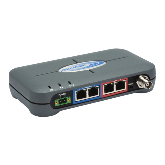
FreeWave FGR2-PE Programming & Installation Manual
Hide thumbs
Also See for FGR2-PE:
- User manual and reference manual (160 pages) ,
- User manual (91 pages)
Advertisement
Quick Links
Programming & Installing the FreeWave Model FGR2-
PE for a Wireless RF MODEM Connection
NOTE: JM Stewart utilizes an industrial 900 MHz RF Transceivers from FreeWave
Technologies, model FGR2-PE.
The FreeWave Wireless Transceiver (Model FGR2-PE) will arrive pre-configured
and installed inside the sign. It is not necessary for you to program these
Transceivers. Please skip to page 18 for installation instructions.
Programming the Transceivers
Start with the Transceiver that will be installed in your Building
1. Plug the Transceiver Ethernet Port #1 into either your computer (using an Ethernet
crossover cable) or a switch/router using a RJ-45 Ethernet cable. Connect the power
adapter to the radio and a 110 volt outlet.
2. You will need to assign your computer a static IP address on the same subnet to
access the radio. You can use 192.168.111.90. See Figure #1.
Figure #1
2201 Cantu Court Suite 215 Sarasota, FL 34232
(941) 378-4242 (800-237-3928 Fax (941) 378-2765
Stewartsigns.com
Page 1 of 23
Advertisement

Related Manuals for FreeWave FGR2-PE


Summary of Contents for FreeWave FGR2-PE
- Page 1 Programming & Installing the FreeWave Model FGR2- PE for a Wireless RF MODEM Connection NOTE: JM Stewart utilizes an industrial 900 MHz RF Transceivers from FreeWave Technologies, model FGR2-PE. The FreeWave Wireless Transceiver (Model FGR2-PE) will arrive pre-configured and installed inside the sign. It is not necessary for you to program these Transceivers.
- Page 2 The default IP address of the Transceiver from the factory is 192.168.111.100. Open your web browser (Internet Explorer) and type 192.168.111.100 into the address bar of your web browser. See figure #2. Figure #2 You will be prompted for a user name and password. The default username for the Administrator login is ‘admin’, the password is ‘admin.’...
- Page 3 Figure #4 Status Window IP Setup: This Window will be used to setup the IP address, Subnet Mask, and Default Gateway of the radio. Please check with your Network Administrator before changing these settings. This Window will also display the MAC address of the radio. 1.
- Page 4 Figure #5 IP Setup Window (Building Unit) b. Enter the IP Address as 192.168.1.50. c. Enter the Subnet Mask as 255.255.255.0. d. Enter the Default Gateway as 192.168.1.1. e. Leave the “Web Page Port” unchanged at 80. f. Record the IP Addresses for each Transceiver on a piece of paper and tape it to the Transceiver for future reference.
- Page 5 Figure #6 “Serial Setup 1” Window (Building Unit) 3. Configuring the “Serial Setup 2”. 1. Click on “Serial Setup 2”. The Serial Setup window will be displayed. See figure 2. Set Mode to “Disabled”. 3. Click on “Save/Apply” to save your settings. 2201 Cantu Court Suite 215 Sarasota, FL 34232 Page 5 of 23 (941) 378-4242 (800-237-3928 Fax (941) 378-2765...
- Page 6 Figure #7 “Serial Setup 2” Window (Building Unit) 4. Configuring the “Radio Setup”. See figure #8. a. Click on “Radio Setup”. b. Set the “Network Type” to “Point-to-Point”. c. Set the Modem Mode to “Gateway”. d. Click on “Save/Apply” to save your settings. e.
- Page 7 Figure #8 Radio Setup Window (Building Unit) Figure #9 Call Book Window (Building Unit) 2201 Cantu Court Suite 215 Sarasota, FL 34232 Page 7 of 23 (941) 378-4242 (800-237-3928 Fax (941) 378-2765 Stewartsigns.com...
- Page 8 Setting up the RF MODEM that will be installed in your Sign 1. Plug the Transceiver into either your computer (using an Ethernet crossover cable) or a switch/router using a RJ-45 Ethernet cable. Connect the power adapter to the radio and a 110 volt outlet.
- Page 9 Figure #12 NOTE: The first Window that you will see is the Status Window. This Window will include all of your device information. Nothing on this screen is user adjustable. See figure #13 Figure #13 Status Window (Sign Unit) 2201 Cantu Court Suite 215 Sarasota, FL 34232 Page 9 of 23 (941) 378-4242 (800-237-3928 Fax (941) 378-2765 Stewartsigns.com...
- Page 10 5. Configuring the “IP Setup” for the RF MODEM that will be installed in your Sign. See figure #14. a. Click on “IP Setup”. The IP Setup Window will be displayed. See figure #14. b. Enter the IP Address as 192.168.1.51. c.
- Page 11 Figure #15 “Serial Setup 1” Window (Sign Unit) 8. Configuring the “Serial Setup 2”. See figure #16. 1. Click on “Serial Setup 2”. The Serial Setup window will be displayed. See figure #15. 2. Set Mode to “Disabled”. 3. Click on “Save/Apply” to save your settings. 2201 Cantu Court Suite 215 Sarasota, FL 34232 Page 11 of 23 (941) 378-4242 (800-237-3928 Fax (941) 378-2765...
- Page 12 Figure #16 “Serial Setup 2” Window (Sign Unit) 9. Configuring the “Radio Setup”. See figure #17. 1. Click on “Radio Setup”. 2. Set the “Network Type to “Point-to Point” 3. Set the Modem Mode to “Endpoint”. 4. Click on “Save/Apply” to save your settings. 5.
- Page 13 Figure #17 Radio Setup Window (Sign Unit) Figure #18 Call Book Window (Sign Unit) 2201 Cantu Court Suite 215 Sarasota, FL 34232 Page 13 of 23 (941) 378-4242 (800-237-3928 Fax (941) 378-2765 Stewartsigns.com...
-
Page 14: Installing The Transceivers
Installing the Transceivers Included in the Transceiver box is the following: a. 2 ea. RF Transceivers installed in a Metal Enclosure. b. 1 set of Antenna adapters c. 1 Antenna Extension cable (to be used inside the sign). d. 1 Bulkhead Connector. e. - Page 15 Figure #20 Transceiver inside the Sign. Connect the RS232 Cable to “COM 1” 2. On ID cabinet ID#1, open the Lid on the LED portion of the sign by removing the Phillips screws on the bezel surrounding the Lexan Lens. 3.
- Page 16 7. Locate the serial cable. This cable has a RJ45 connector on one end and a Panduit connector on the other end. Connect the RJ45 connector to the Serial Port on the Transceiver identified as “COM 1”. a. On Traditional CPU boards, attach the Panduit connector to the RS232 port CPU labeled “RS232”...
-
Page 17: Mounting The External Antenna
Figure #21a New CPU Board inside the Sign Mounting the External Antenna 1. Drill a 5/8” hole in ID#1 side of LED cabinet 9 inches below the top of the LED cabinet to accommodate the bulkhead connector. Be careful not to interfere with the light Sensor mounted inside the cabinet. - Page 18 Figure #22 Mounting the External Antenna Figure #23 Installing the Bulkhead Connector 3. For weather proof seal wrap external half of the bulkhead connector as well as 2 inches of the base of the antenna in the Arlon Silicone Self-Fusing Electrical Tape. See figure #23 4.
- Page 19 Figure #23 Wrapping the Antenna in Silicone Self-Fusing Electrical Tape Connecting your Transceiver to the PC in your Building 1. Locate the Serial cable included with Transceiver. Attach one end of this cable to the #1 COM Port on the Transceiver. See figure #25. 2.
-
Page 20: Troubleshooting
Figure #25 The Transceiver Inside Your Building Troubleshooting Verifying Wireless Communications When the Transceivers are in range of each other they will continuously “hand-shake” or communicate with each other. This is indicated by a solid Green CD Light and a Flashing Red CTS light. - Page 21 Testing the RF Modems by Performing a Loopback Test 1. Remove the end of the serial cable connected to the CPU board inside ID#1 side of the sign. (This is the cable coming from the COM1 port on MODEM inside the sign).
- Page 22 Figure #27 5. Select the connection type to be used. From the “Connect using” drop-down menu and select the P.C. Serial Port you plugged the serial cable into. (this is usually COM1), 6. Click on the OK button. The “Properties” dialog box appears for the selected connection type.
- Page 23 7. After selecting the appropriate menu items for each setting, click the “Apply” button and then the “OK” button. A Hyper Terminal window will appear. See figure #21 Figure #21 8. You should be able to type characters on the Hyper Terminal window. These characters should echo back to the window.
Need help?
Do you have a question about the FGR2-PE and is the answer not in the manual?
Questions and answers