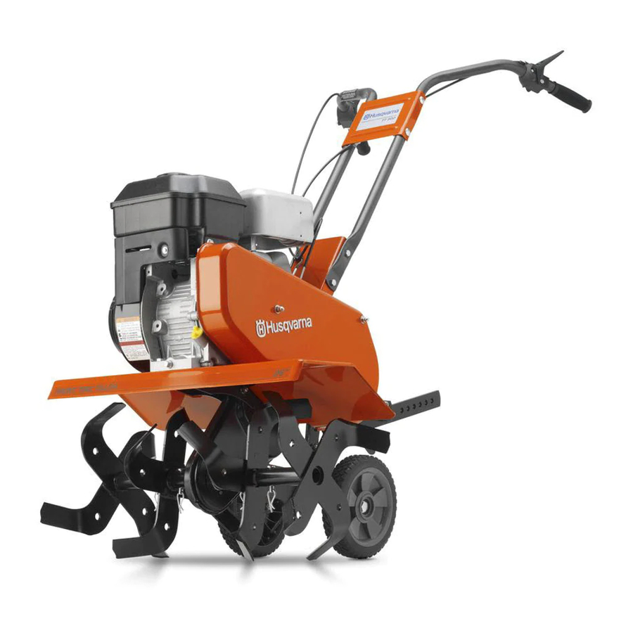
Husqvarna FT900 Owner's Manual
Walk-behind powered rotary tillers
Hide thumbs
Also See for FT900:
- Illustrated parts list (13 pages) ,
- Operator's manual (25 pages) ,
- Operator's manual (24 pages)

Related Manuals for Husqvarna FT900


Summary of Contents for Husqvarna FT900
- Page 1 FT900 Owner's Manual "This machine is approved by the EPA for E10 (10% ethanol) and lower fuel only. Do not use any fuel >E10 in this machine." 532 43 99-99...
-
Page 2: Maintenance And Storage
Safe Operation Practices for Walk-Behind Powered Ro ta ry Tillers TRAINING • Read the Owner’s Manual care ful ly. Be thor ough ly fa mil iar with the controls and the proper use of the equip ment. Know how to stop the unit and disengage the controls quickly. -
Page 3: Table Of Contents
PRODUCT SPECIFICATIONS Gasoline Capacity: 3 Quarts (2.8L) Unleaded Regular Oil (API-SG-SL): SAE 30 (Above 32°F/0°C) (Capacity: 21 oz./0.6L) SAE 5w30 (Below 32°F/0°C) Spark Plug : Champion RC12YC (Gap: .030"/0.76mm) CONGRATULATIONS on your purchase of a new tiller. It has been designed, en gi neered and manu fac tured to give you the best pos sible de penda bil ity and per form ance. -
Page 4: Assembly
Your new tiller has been assembled at the factory with exception of those parts left unassembled for shipping purposes. To ensure safe and proper operation of your tiller all parts and hardware you assemble must be tightened securely. Use the correct tools as necessary to insure proper tightness. TOOLS REQUIRED FOR ASSEMBLY A socket wrench set will make assembly easier. -
Page 5: Assembly
UNPACK CARTON & INSTALL HANDLE (See Fig. 2) CAUTION: Be careful of exposed sta ples when handling or disposing of cartoning material. IMPORTANT: WHEN UNPACKING AND AS SEM BLING TILLER, BE CAREFUL NOT TO STRETCH OR KINK CABLE(S). • Cut cable ties securing handles. •... -
Page 6: Product View
KNOW YOUR TILLER READ THIS MANUAL AND SAFETY RULES BEFORE OPERATING YOUR TILLER. Compare the illustrations with your tiller to familiarize yourself with the location of various controls and adjustments. Save this manual for future reference. These symbols may appear on your Tiller or in literature supplied with the product. Learn and understand their meaning. FORWARD TINE CONTROL REVERSE TINE... -
Page 7: Stopping Tines/Engine
The operation of any tiller can result in foreign objects thrown into the eyes, which can result in severe eye damage. Always wear safety glasses or eye shields before starting your til- ler and while tilling. We recommend a wide vision safety mask over spectacles or standard safety glasses. -
Page 8: Before Starting Engine
TO TRANSPORT CAUTION: Before lifting or trans port ing, allow tiller engine and muffler to cool. Disconnect spark plug wire. gasoline from fuel tank. AROUND THE YARD • Tip depth stake forward until it is held by the stake spring. •... -
Page 9: Tilling Hints/Cultivating
NOTE: If engine does not start, see troubleshooting points. SPARK PLUG CHOKE CON TROL RECOIL STARTER Fig. 8 BREAKING IN YOUR TILLER Break-in your belt(s), pulleys and tine control before you actually begin tilling. • Start engine, tip tines off ground by pressing handles down and engage tine control to start tine rotation. -
Page 10: Lubrication Chart
MAINTENANCE SCHEDULE FILL IN DATES AS YOU COMPLETE REGULAR SERVICE Check Engine Oil Level Change Engine Oil Oil Pivot Points Inspect Spark Arrester / Muffler Inspect Air Screen Clean or Replace Air Cleaner Cartridge Clean Engine Cylinder Fins Replace Spark Plug 1 - Change more often when operating under a heavy load or in high ambient temperatures. -
Page 11: Engine Lubrication
Disconnect spark plug wire before performing any maintenance (except carburetor adjustment) to prevent accidental starting of engine. Prevent fires! Keep the engine free of grass, leaves, spilled oil, or fuel. Remove fuel from tank before tipping unit for maintenance. Clean muffler area of all grass, dirt, and debris. Do not touch hot muffler or cylinder fins as contact may cause burns. -
Page 12: Cooling System
COOLING SYSTEM (See Fig. 14) Your engine is air cooled. For proper engine performance and long life keep your engine clean. • Clean air screen frequently using a stiff-bristled brush. • Remove blower housing and clean as necessary. • Keep cylinder fins free of dirt and chaff. CYLINDER FINS MUFFLER Fig. -
Page 13: Service & Adjustments
SERVICE AND ADJUSTMENTS CAUTION: Disconnect spark plug wire from spark plug and place wire where it cannot come into contact with plug. TILLER TO ADJUST HANDLE HEIGHT (See Fig. 15) Factory assembly has provided lowest handle height. Se lect handle height best suited for your tilling conditions. Handle height will be different when tiller digs into soil. -
Page 14: Service And Adjustments
SERVICE AND ADJUSTMENTS TO REMOVE BELT GUARD (See Fig. 19) • Remove two (2) cap nuts and washers from side of belt guard. • Loosen (do not remove) tine shield nut on underside of tine shield. • Pull belt guard out and away from unit. •... -
Page 15: Service & Adjustments
SERVICE AND ADJUSTMENTS CHECK TINE OPERATION • See “TINE OPERATION CHECK” in this section of manual. REPLACE BELT GUARD FORWARD MOTION (INSIDE) V-BELT ENGINE PULLEY BELT GUIDE REVERSE IDLER PULLEY BELT GUIDE FORWARD IDLER PULLEY REVERSE (OUTSIDE) V-BELT REVERSE IDLER PULLEY ENGINE PULLEY FORWARD... -
Page 16: Storage
Immediately prepare your tiller for storage at the end of the season or if the unit will not be used for 30 days or more. WARNING: Never store the tiller with gasoline in the tank inside a build ing where fumes may reach an open flame or spark. -
Page 17: Troubleshooting
TROUBLESHOOTING POINTS PROBLEM CAUSE Will not start 1. Out of fuel. 2. Engine not “CHOKED” properly. 3. Engine flooded. 4. Dirty air cleaner. 5. Water in fuel. 6. Clogged fuel tank. 7. Loose spark plug wire. 8. Bad spark plug or improper gap. 9. -
Page 18: Repair Parts
TILLER - MODEL NO. FT900 (96083000501), PRODUCT NO. 960 83 00-05 HANDLE ASSEMBLY FT-handle_assy_5 PART DESCRIPTION 532 44 07-18 Panel, Control 872 14 05-12 Bolt, RDHD 5/16-18 x 1 1/2 532 16 57-87 Grip, Handle 532 44 07-14 Handle, LH Double Bend 873 68 05-00 Nut, Crown Lock 5/16 -18 819 11 11-16 Washer 11/32 x 11/16 x 16 Ga. - Page 19 TILLER - MODEL NO. FT900 (96083000501), PRODUCT NO. 960 83 00-05 BELT GUARD AND PULLEY ASSEMBLY belt_guard_14 PART DESCRIPTION 532 43 91-62 Assembly, Bracket, Belt Guard 532 00 94-84 Clip, Cable 532 08 67-77 Screw #10-24 x 1/2 874 61 08-12 Bolt, Hex Head 1/2-20 x 3/4 873 68 06-00 Nut, Hex 3/8-16 819 13 13-16 Washer 13/32 x 13/16 x 16 Ga.
- Page 20 TILLER - MODEL NO. FT900 (96083000501), PRODUCT NO. 960 83 00-05 WHEEL AND DEPTH STAKE ASSEMBLY PART DESCRIPTION 532 00 91-94 Pin, Clevis 874 76 05-20 Bolt, Hex Head 5/16-18 x 1-1/4 874 76 05-12 Bolt, Hex Head 5/16-18 x 3/4...
-
Page 21: Tine Assembly
TILLER - MODEL NO. FT900 (96083000501), PRODUCT NO. 960 83 00-05 TINE ASSEMBLY PART DESCRIPTION 532 15 69-34 Tine, Outer, R.H. 532 00 31-46 Retainer, Spring 532 15 69-32 Tine, Inner, R.H. PART 532 15 69-31 532 15 69-33 532 00 49-29... - Page 22 TILLER - MODEL NO. FT900 (96083000501), PRODUCT NO. 960 83 00-05 TRANSMISSION PART DESCRIPTION 874 76 05-24 Bolt, Hex 5/16-18 x 1-1/2 Gr. 2 874 78 06-52 Bolt, Hex 3/8-16 x 3-1/4 819 13 13-11 Washer 13/32 x 13/16 x 11...
- Page 23 TILLER - MODEL NO. FT900 (96083000501), PRODUCT NO. 960 83 00-05 DECALS PART DESCRIPTION 532 44 06-13 Decal, Logo 532 42 20-12 Decal, Logo 532 43 99-89 Decal, Logo 532 11 06-14 Decal, Hand Placement 532 15 87-00 Decal, Control Forward...
- Page 28 11.29.10 CL Printed in the U.S.A.
Need help?
Do you have a question about the FT900 and is the answer not in the manual?
Questions and answers
Choke and gas settings to start tiller
To start the Husqvarna FT900 tiller, use the choke control when starting a cold engine. Adjust the throttle control to set the engine speed as needed.
This answer is automatically generated
E Husqvama® PRODUCT PRODUIT MAINTENANCE LEVEL NIVEAU DE MAINTENANCE SERIAL NUMBER NUMERO DE SERIE , 960830006 02 MODEL / MODELE 020413M 013735 MODEL NUMBER / NUMERO DE MODELE FT900 R SERVICE CALL / POUR LE SERVICE APPELER 800 - 448 - 7543 SEMBLED IN U.6.A. / A66EMBLÉ AUX ÉTATS - UNIS RAE. 84 31055 CONFORMS TO Directions for settings
This tiller has three filler caps and two drain plugs. Is that a requirement to oil the gears for the tiller or does the oil for the tiller also takes care of the gears in the tiller ?