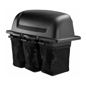
Husqvarna 42" Collection System Operator And Parts Manual
42" and 48" collection system
Hide thumbs
Also See for 42" Collection System:
- Operator and parts manual (16 pages) ,
- Operator and parts manual (12 pages)
Advertisement
Advertisement
Table of Contents

Summary of Contents for Husqvarna 42" Collection System
- Page 1 Operator and Parts Manual Collection System 42" and 48" / 966805002...
- Page 2 KNOW YOUR BLOWER SYSTEM CONGRATULATIONS on the purchase of a new collection system. It has been designed, engineered READ THIS OPERATION MANUAL AND SAFETY and manufactured to give you the best possible RULES BEFORE ASSEMBLING OR OPERATING dependability and performance. YOUR BLOWER SYSTEM.
-
Page 3: Table Of Contents
CONTENTS SAFETY RULES ............4 SERVICE ............5 OPERATION ............. 11 TIPS FOR IMPROVED BAGGING ....11 GENERAL RECOMMENDATIONS ....11 REPAIR PARTS ............12 BLOWER ............12 CHUTES, MOUNTS, BELTS ......14 BAGGER ............16 TOOLS REQUIRED CONTAINER CONTENTS • Blower Assembly • Containers • Wrench or ratchet and socket "... -
Page 4: Safety Rules
SAFETY RULES SAFE OPERATION PRACTICES FOR RIDE-ON MOWERS DANGER ! THIS CUTTING MACHINE IS CAPABLE OF AMPUTATING HANDS AND FEET AND THROWING OBJECTS. FAILURE TO OBSERVE THE FOLLOWING SAFETY INSTRUCTIONS COULD RESULT IN SERIOUS INJURY OR DEATH. GENERAL OPERATION • Keep machine free of grass, leaves or other •... -
Page 5: Service
SAFETY RULES SAFE OPERATION PRACTICES FOR RIDE-ON MOWERS CHILDREN • Keep machine free of grass, leaves, or other debris buildup. Clean oil or fuel spills. Allow Tragic accidents can occur if the operator is not machine to cool before storing. alert to the presence of children. - Page 6 ASSEMBLY BAGGER SUPPORT ASSEMBLY Draw Bar B Draw Bar A 1. Remove the upper bolts on each side of the 1. Slide the flanges of the support assembly in the drawbar and replace them with the shoulder bolts slots in the drawbar. supplied with the collection kit.
- Page 7 ASSEMBLY DECK ADJUSTMENT MOUNTING BLOWER ASSEMBLY 1. Locate the rear adjustment nut on the discharge 1. Remove the discharge chute from the deck. side of the deck. To assure the right tighteness, 2. Lower deck to the lowest cutting position. mark the front side of the nut.
- Page 8 ASSEMBLY INSTALLING DRIVE BELT INSTALLING BELT COVERS 1. Place the deck belt shield on the deck over the NOTE: The kit provides parts for both the 42" and 48". drive pulley and secure with hardware removed Refer to the parts list on page 14 for the correct belt for from steel belt shield.
- Page 9 ASSEMBLY INSTALLING CHUTE SUPPORT MOUNTING COVER ASSEMBLY 1. Position upper chute support against bagger inlet, NOTE: Assistance from another person may ease flush at outer edges. See Illustration. mounting the cover assembly to mower. 1. Lift and rotate cover to align the cover brackets 2.
- Page 10 ASSEMBLY INSTALLING SPACER PLUGS CONTAINER INSTALLATION 1. Remove plastic end caps from the center two bag 1. Install containers on support frame, overlapping support arms. Fully insert spacer plugs into the containers at center tube. ends of the support tubes. It may be necessary NOTE: One container should always overlap the other to tap the spacers into place with a hammer or container at the center tube.
-
Page 11: Operation
OPERATION TIPS FOR IMPROVED BAGGING Follow the mower operation instructions in you mower • If the grass catcher fails to pick up cut grass operator’s manual. or leaves, it is an indication that clogging has When operating your grass catcher on a lawn where occurred in the system or that the grass catcher grass and leaf bagging equipment has not been containers are full. -
Page 12: Repair Parts
REPAIR PARTS BLOWER... - Page 13 REPAIR PARTS ITEM PART NO. QTY. DESCRIPTION ITEM PART NO. QTY. DESCRIPTION 1.. 539 130344 ..1 ..HOUSING w/DECALS 30.. 539 125229 ..1 ..KEY x 1½ 2.. 539 130293 ..1 ..COVER, BELT 31.. 539 130317 ..1 ..PIN 3..
-
Page 14: Chutes, Mounts, Belts
REPAIR PARTS CHUTES, MOUNTS, BELTS... - Page 15 REPAIR PARTS ITEM PART NO. QTY. DESCRIPTION ITEM PART NO. QTY. DESCRIPTION 1.. 522 739202 ..1 ..CHUTE, UPPER 48 10.. 539 105743 ..1 ..DECAL, NO STEP 532 187299 ..1 ..CHUTE, UPPER 42 11.. 539 104411 ..1 ..KNOB w/ STUD 2..
-
Page 16: Bagger
REPAIR PARTS BAGGER... - Page 17 REPAIR PARTS ITEM PART NO. QTY. DESCRIPTION ITEM PART NO. QTY. DESCRIPTION 1.. 532 195373 ..1 ..COVER 10.. 532 192603 ..1 ..GASKET, COVER 2.. 532 400226 ..3 ..CONTAINER, SOFT BAG 11.. 539 110281 ..1 ..SUPPORT, CHUTE 3..
- Page 20 115 429326 Rev C 2012-07-15...


Need help?
Do you have a question about the 42" Collection System and is the answer not in the manual?
Questions and answers