Honeywell Dolphin 6100 User Manual
Mobile computer with windows ce 5.0
Hide thumbs
Also See for Dolphin 6100:
- User manual (104 pages) ,
- Quick start manual (15 pages) ,
- Quick start manual (9 pages)
Table of Contents
Advertisement
Advertisement
Table of Contents

Related Manuals for Honeywell Dolphin 6100


Summary of Contents for Honeywell Dolphin 6100
-
Page 1: Mobile Computer
™ Dolphin 6100 Mobile Computer ® with Windows CE 5.0 User’s Guide... - Page 3 Disclaimer Honeywell International Inc. (“HII”) reserves the right to make changes in specifications and other infor- mation contained in this document without prior notice, and the reader should in all cases consult HII to determine whether any such changes have been made. The information in this publication does not rep- resent a commitment on the part of HII.
-
Page 5: Table Of Contents
Installing Memory Cards ....................3-9 Right Side Panel Features ....................3-10 Top Panel Features ......................3-10 Bottom Panel Features ......................3-11 Dolphin Peripherals/Accessories for the Dolphin 6100 ............3-11 Dolphin USB Communication Cable ..................3-12 Battery Power ........................3-12 Resetting the Terminal .......................3-15 Soft Reset (Warm Boot) ....................3-15 Hard Reset (Cold Boot)....................3-16... - Page 6 Front Panel ......................... 9-2 Back Panel ......................... 9-2 Powering the Dolphin HomeBase Device................9-3 eBase Clamp-on Ferrite Core Installation ................9-4 Charging the Main Battery....................9-5 Checking Battery Power ...................... 9-6 Technical Specifications ...................... 9-7 Chapter 10 - Dolphin 6100 Net Base Device...
- Page 7 Overview..........................10-1 Parts and Functions......................10-2 Front Panel ........................10-2 Back Panel ........................10-3 Bottom Panel ....................... 10-4 Power ..........................10-4 Connecting Power to the Net Base................10-4 Charging the Main Battery....................10-5 To Power a Terminal and Charge its Main Battery............10-5 Communication........................
-
Page 9: Chapter 1 - Agency Approvals
Agency Approvals Label Locations Dolphin 6100 mobile computers meet or exceed the requirements of all applicable standards organizations for safe operation. However, as with any electrical equipment, the best way to ensure safe operation is to operate them according to the agency guidelines that follow. Read these guidelines carefully before using your mobile computer. -
Page 10: Safety & Rf Approvals By Country
89/336/EEC Electromagnetic Compatibility Directive and the 73/23/ EEC and 93/68/EEC Low Voltage Directive. Honeywell shall not be liable for use of our product with equipment (i.e., power supplies, personal computers, etc.) that is not CE marked and does not comply with the Low Voltage Directive. -
Page 11: Dolphin Rf Terminal-802.11B/G And/Or Bluetooth
Laser Safety Label If the following label is attached to your product, it indicates the product contains a LASER LIGHT. DO NOT STARE INTO BEAM laser engine or laser aimer. CLASS 2 LASER PRODUCT 1.0 mW MAX OUTPUT: 650nM IEC 60825-1:1993+A1+A2 Complies with 21 CFR 1040.10 and 1040.11 Laser Eye Safety Statement: This device has been tested in accordance with and except for deviations pursuant to Laser... -
Page 12: Canadian Compliance
Cet appareil numérique de la Classe B est conforme à la norme NMB-003 du Canada. For European Community Users Honeywell complies with Directive 2002/96/EC OF THE EUROPEAN PARLIAMENT AND OF THE COUNCIL of 27 January 2003 on waste electrical and electronic equipment (WEEE). -
Page 13: Chapter 2 - Getting Started
12-1. Step 1. Install the Main Battery The Dolphin 6100 is shipped with the battery packaged separate from the unit. Follow the steps below to install the main battery. 1. Release the strap making it convenient to reach the door. -
Page 14: Led Indicators
Battery is full or fully charged Green LED On We recommend use of Honeywell peripherals, power cables, and power adapters. Use of any non- Honeywell peripherals, cables, or power adapters may cause damage not covered by the warranty. DO NOT attempt to charge damp/wet mobile computers or batteries. All components must be dry before connecting to an external power source Step 3. -
Page 15: Desktop
AP.) Double tap to configure your WLAN Secure Wireless Client. For complete configuration instructions, download the Honeywell Secure Wireless (SWC) Client User’s Guide from www.honeywellaidc.com. Indicates that the USB communication cable is connected. Double tap to display USB status window. -
Page 16: Using The Stylus
Icon Meaning Indicates the status of battery power. Double tap to open the Power control panel setting. When this icon shows a red power plug, it indicates the device is using external power. Displays the current time. Double tap to change the time and date. Indicates whether the keypad is standard alpha (upper and lower case), all caps alpha, or in numeric mode. -
Page 17: Selecting Programs
Selecting Programs Tap Start -> Programs. To open a program, tap the icon on the menu. Pop-Up Menus You can quickly choose an action for an item using the pop-up menus. 1. Tap and hold the stylus on the item name. The pop-up menu appears. 2. - Page 18 2 - 6...
-
Page 19: Chapter 3 - Terminal Hardware Overview
Terminal Hardware Overview Dolphin 6100 terminals include a number of standard terminal configurations as well as charging and communication peripherals and accessories to maximize the efficiency of your application setting. Standard Terminal Configurations There are two standard Dolphin 6100 configurations: WPAN only and WPAN/WLAN. Both configurations include the following options;... -
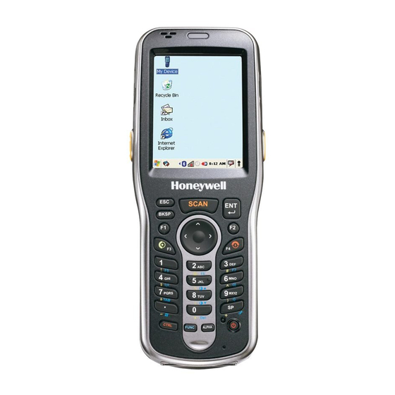
Page 20: Front Panel Features
Front Panel Features Touch Screen Display (screen protector installed at the factory) Scan key Keypad Navigation (28-key keys numeric) Power key Software Reset key Scan/Decode LED Note: The LED is user-programmable. LED Color Meaning Lights when Scan button pressed in scanning applications. -
Page 21: Display Backlight
Dolphin 6100s ship with a screen protector already installed over the touch screen to help prevent damage to the touch screen. Do NOT remove this screen protector before initial use. Honeywell recommends using screen protectors, especially for applications that require high volume interfacing with the touch screen. For more information, see... - Page 22 Honeywell. Contact a Honeywell sales representative for details. Honeywell also mandates use of a proper stylus, which is one that has a stylus tip radius of no less than 0.8mm. Use of the Honeywell stylus included with the terminal is recommended at all times.
- Page 23 2. Clean the touch panel thoroughly with a clean, non-abrasive, lint-free cloth. Make sure nothing is on the touch panel. 3. Release the left edge of the backing paper on the screen protector. 4. Align the exposed edge of the screen protector along the left edge of the touch panel. Make sure that it lies flush with edges of the touch panel.
- Page 24 6. Pull smoothly and evenly from left to right until the screen protector is applied. Press gently but firmly. Use the card as necessary to smooth out any air pockets or bumps after application. 7. Press the Power key to wake the terminal and check the touch panel with the stylus. 8.
- Page 25 12. For maximum performance, recalibrate the screen. Tap Start -> Settings -> Control Panel -> double tap Stylus -> Calibration tab. 13. Tap Recalibrate and follow the instructions on the screen. 3 - 7...
-
Page 26: Back Panel Features
• 1KHz–72db • 4KHz–72db Stylus Dolphin 6100 terminals ship with a stylus inserted in a loop on the hand strap. Store the stylus in the hand strap when you’re not using it; see Using the Stylus on page 2-4. 3 - 8... -
Page 27: Left Side Panel Features
When closed, the side door seals the terminal from moisture and particle intrusion thus preserving the terminal’s environmental rating. Installing Memory Cards The Dolphin 6100 supports Micro Secure Digital (SD) memory cards. 2GB and 4GB cards have been tested for reliability. Please contact your Honeywell sales representative for available qualified card options. -
Page 28: Right Side Panel Features
Right Side Panel Features Headset Jack Side Button Headset Jack The rubber door on the right side panel provides access to the headset jack. This is a 2.5mm audio jack that supports a headset with a mono speaker and microphone. When closed, the side door seals the terminal from moisture and particle intrusion thus preserving the terminal’s environmental rating. -
Page 29: Bottom Panel Features
I/O Connector The I/O mechanical connector is designed to work exclusively with Dolphin 6100 peripherals and cables. This connector powers the terminal, charges the main battery, and facilitates communication. This connector supports full speed USB 1.1 communication (up to 12 Mbps) and RS-232 communications with a maximum speed of 115Kbps and seven baud rate settings. -
Page 30: Dolphin Usb Communication Cable
9-1. Dolphin Net Base Device The Dolphin Net Base enables up to four Dolphin 6100 mobile computers to communicate with a host device over an Ethernet network. In addition, the Net Base provides a second RJ45 Ethernet port for connection to an additional device, such as a printer, workstation, eBase, or another Net Base. - Page 31 Both batteries must be charged to full capacity before using the Dolphin 6100 for the first time! Charge the main battery pack with the Dolphin charging cable for a minimum of 4 or 6 hours depending on your battery before initial use.
- Page 32 Note: If the main battery is low and the terminal is in Suspend Mode, pressing the button does wake the Dolphin 6100 terminal; you must replace the discharged battery with a fully charged battery or apply AC power to the terminal. Checking Battery Power Power icons appear in the command bar at the bottom of the window.
-
Page 33: Resetting The Terminal
• Although your battery can be recharged many times, it will eventually be depleted. Replace it after the battery is unable to hold an adequate charge. • If you are not sure the battery or charger is working properly, send it to Honeywell International Inc. or an authorized service center for inspection. -
Page 34: Hard Reset (Cold Boot)
1. Press and hold the Reset button and then press and release the Power button. The screen turns white and the decode and scan LED flashes red for approximately three seconds. 2. The terminal re-initializes, which re-installs all programs stored in the \Honeywell\Autoinstall folder. -
Page 35: Care And Cleaning Of The Dolphin Terminal
Memory 128MB RAM X 128MB Flash Storage Expansion User accessible Micro SD memory card slot. Please contact your Honeywell sales representative for available qualified card options. Display 2.8 in. transmissive active matrix 65K color LCD with backlight, QVGA (240 x 320) - Page 36 WLAN (optional) Dual Mode 802.11 b/g (11 Mbps/54 Mbps) with internal antenna WLAN Security Wi-Fi Certified, 802.1X, WPA2, EAP, WEP, LEAP, TKIP, MSD, EAP-TLS, EAP-TTLS, WPA- PSK, PEAP, CCXv4 Operating Temperature 14° to122°F (-10° to 50°C) Charging Temperature 32° to 104°F (0° to 40°C) Storage Temperature -4°...
-
Page 37: Chapter 4 - Using The Keypad
Using the Keypad Numeric Keypad Layout Navigation keys Power key Navigation Keys Located in the center of the keypad for easy access with either hand, the navigation keys enable you to move the cursor up and down lines and from character to character. 4 - 1... -
Page 38: Basic Keys
Basic Keys Name Function ALPHA Toggles the keypad between alpha (upper and lowercase) and numeric modes. Indicator changes accordingly on the command bar. Backspace Backspace moves the cursor back one space. If you are typing text, a character is deleted each time you press the backspace key. -
Page 39: Function Key Combinations
Note that when typing in alpha mode, you must use the same multi-press method you would use when typing letters on a phone keypad. Each key press types the next letter in the sequence as displayed by the alpha indicator. Function Key Combinations The Function key (FUNC) modifies the next key pressed to perform specific functions. -
Page 40: Ctrl Key Combinations
Buttons can be programmed to execute different functions using the Program Button program in the Control Panel. The following buttons on the Dolphin 6100 are programmed for the listed function. Press and hold the Function (FUNC) key and press the appropriate function key to execute the indicated function. -
Page 41: Chapter 5 - Using The Image Engine
Available Image Engines The Dolphin 6100 can be equipped with a 5300SR, 5300SF, 5300HD, 5100SR, 5100SF, or 5100HD image engine (depending on the configuration purchased). Depth of Field 5300 Standard Range (5300SR) 8.3 mil... - Page 42 5300 High Density (5300HD) 5 mil 6.6 mil 8.3 mil Data 8.3 mil QR 15 mil 13 mil UPC Linear PDF417 Matrix Linear Working Range*: Near 2.4 in. 2.1 in. 2.6 in. 2.5 in. 1.6 in. 2.1 in. (6.1cm) (5.3cm) (6.6cm) (6.4cm) (4.1cm)
- Page 43 5100 High Density (5100HD) 5 mil 6.6 mil 8.3 mil Data 8.3 mil QR 15 mil 13 mil UPC Linear PDF417 Matrix Linear Working Range*: Near 2.4 in. 2.1 in. 2.6 in. 2.5 in. 1.6 in. 2.1 in. (6.1cm) (5.3cm) (6.6cm) (6.4cm) (4.1cm)
-
Page 44: Supported Bar Code Symbologies
Supported Bar Code Symbologies Symbology Type Symbology Name 1D Symbologies Codabar Interleaved 2 or 5 Code 3 of 9 Matrix 2 of 5 Code 11 Plessey Code 32 Pharmaceutical (PARAF) PosiCode Code 93 Straight 2 of 5 IATA Code 128 Straight 2 of 5 Industrial EAN with Add-On Telepen... -
Page 45: Activating The Engine
Activating the Engine When a scanning application is open, press the Scan key to activate the image engine. Using Demos Dolphin Demos are software utilities loaded on all Dolphin terminals that demonstrate the advanced features of the terminal. There are two Demos that feature the image engine: Image Demo and Scan Demo. -
Page 46: Capturing Images (5300 Engine Only)
Sample Bar Codes You can use the following bar codes to verify decoding: Sample 128 Sample PDF417 Code 128 PDF417 Test Message Omni-Directional Scanning Positions The high-vis aiming pattern frames the bar code to provide you with the best scanning performance. Note: To achieve the best read, the aiming beam should be centered horizontally across the bar code. - Page 47 Taking an Image 1. Tap Start -> Programs -> Demos -> Image Demo. 2. Point the Dolphin terminal at the object. 3. Press the Scan key to activate the engine. The touch screen displays a preview of the object. 4. Adjust the terminal’s position until the preview on the screen is as you want it to appear in the image. 5.
- Page 48 5 - 8...
-
Page 49: Chapter 6 - Using The Laser Engine
Using the Laser Engine Overview The Dolphin 6100 (IS4813 laser version) contains a laser diode that emits a beam toward an oscillating mirror that scans through the code and the reflected light is bounced off of two mirrors back to the collector. -
Page 50: Activating The Engine
Activating the Engine When a scanning application is open, press the Scan key to activate the laser engine. Using Demos Dolphin Demos are software utilities loaded on Dolphin terminals that demonstrate the advanced features of the terminal. To access these demos, tap Start > Programs > Demos. •... -
Page 51: Chapter 7 - Communication
7-6. Installing Additional Software Dolphin terminals ship with the operating system, radio drivers, and custom Honeywell software already installed. These are the default programs that install when your terminal first boots up. You can install additional software programs on the terminal provided that the following parameters are met: •... -
Page 52: Connecting The Usb Charging/Communication Cable
To facilitate USB communication between the Dolphin terminal and the host workstation, you may connect your unit to a host by using either the optional Dolphin 6100-USB Communication Cable or HomeBase. If you use the Communication Cable, slide the cable unit onto the bottom of the terminal lining up the terminal’s I/O connector with the cable unit’s connector. - Page 53 Hardware Requirements for Setup • Dolphin communication peripheral • Dolphin power cable • USB Cable (for USB communication) • ActiveSync v4.1 or higher installed on the host workstation • Windows 98 Second Edition, Windows Me, Windows 2000, Windows NT (4.0 SP6 or higher) or Windows XP computer.
- Page 54 Tap Change Connection to change the current settings. Connection Options Select this option to … ‘USB Establish a USB connection. Communicating with the Dolphin Terminal After setting up both the workstation and the terminal, ActiveSync connection should be automatic. 1. Connect the Dolphin terminal to a communication peripheral, such as the Dolphin HomeBase. 2.
-
Page 55: Adding Programs Via Activesync
The Mobile Device folder opens in Windows Explorer. The Dolphin terminal is now treated as a mass storage device, and transferring files is as simple as dragging and dropping or copying and pasting as you would for moving files between folders on your hard drive. -
Page 56: Wireless Radios
Configuring the WLAN Radio The WLAN radio is configured in the Honeywell WLAN Security Supplicant, which you access by double tapping the program icon in the command bar. 7 - 6... -
Page 57: Adding Programs From The Internet
For complete configuration instructions, download the Honeywell Secure Wireless (SWC) Client User’s Guide from www.honeywellaidc.com. A link to this guide appears on the Dolphin 6100 product page. Adding Programs from the Internet When you have established a network connection (whether via Wireless LAN, Bluetooth, or ActiveSync), you can access the Internet and download additional software programs. - Page 58 7 - 8...
-
Page 59: Chapter 8 - Bluetooth Handler
Connecting Bluetooth devices usually requires that they be paired; the same passkey must be entered for each device. If you want to connect the Dolphin 6100 to a device without any input method (e.g., printers, headsets), refer to the user documentation that accompanied the device for pairing information. -
Page 60: Setting Up A Connection To A Mobile Phone
GPRS data transfer and if it has an available Bluetooth connection. If your phone supports 3G data transfer, you should be able to connect the Dolphin 6100 to your phone. 1. Determine if your phone is configured and connected to GPRS. -
Page 61: Chapter 9 - Dolphin Homebase/Ebase Device
Note: The information in this chapter applies to both the Dolphin HomeBase and Dolphin eBase devices unless otherwise indicated. As the hub of your Dolphin 6100 system, the Dolphin HomeBase charging and communication cradle supports full-speed USB 1.1 and RS-232 communication with a workstation. The Dolphin eBase is identical to the Dolphin HomeBase except it supports Ethernet communication as well as USB 1.1 and... -
Page 62: Front Panel
Front Panel Terminal Well Charging LED Terminal Well Place the Dolphin terminal in the terminal well to communicate with a host device, power the terminal, and charge the terminal’s battery. Make sure that the device is securely seated. Rubber Feet The bottom panel has four rubber feet to stabilize the unit on a flat surface. -
Page 63: Powering The Dolphin Homebase Device
When a terminal is properly seated, the base powers the terminal, charges the terminal’s main battery pack, and launches ActiveSync (see ActiveSync Communication on page 7-2). Honeywell recommends that you leave the base connected to its power source at all times, so that it is always ready to use. 9 - 3... -
Page 64: Ebase Clamp-On Ferrite Core Installation
eBase Clamp-on Ferrite Core Installation We recommend that you install the clamp-on ferrite core included with your Dolphin eBase on your Ethernet cable. Installation of the ferrite is required to meet the declared FCC emission levels. The following illustration shows how to install the ferrite on the cable. It should be placed approximately 1.57 inches (40mm) from the RJ45 plug. -
Page 65: Charging The Main Battery
Charging the Main Battery The base powers the terminal and fully charges its main battery pack in 4 or 6 hours depending on the battery. As battery packs charge, the charging circuitry follows the two-step charging process (CC-CV) that is recommended for Li-Ion batteries. The process monitors changes in temperature, current, and voltage. -
Page 66: Checking Battery Power
Charging a Spare Battery The base can also charge a second battery while the terminal is positioned in the base. The second battery can be inserted in the battery charging well in back of the terminal connection. Angle the battery as shown. -
Page 67: Technical Specifications
Technical Specifications Structural Dimensions 5.3 in. high X 4.5 in. wide X 3.1 in. deep (13.5 cm. X 11.4 cm. X 7.9 cm.) Weight Dolphin HomeBase - 11.0 oz. (313g) Dolphin eBase - 11.3 oz (320g) Material Polycarbonate Color Black Environmental Operating Temperature 14°... - Page 68 9 - 8...
-
Page 69: Chapter 10 - Dolphin 6100 Net Base Device
Dolphin 6100 Net Base Device Overview The Net Base enables up to four Dolphin 6100 mobile computers to communicate with a host device over an Ethernet network. In addition, the Net Base provides a second RJ45 Ethernet port for connec- tion to an additional device such as a printer, workstation, eBase, or another Net Base. -
Page 70: Parts And Functions
Parts and Functions Front Panel Terminal Wells Power/Dock LED COMM LED Terminal Wells The Net Base contains four terminal wells. Each well has its own dedicated Power/Dock LED and COMM LED indicator. Place the Dolphin terminal in any one of the four wells to communicate with a host device, power the terminal, and charge the installed battery pack. -
Page 71: Back Panel
Green LED Yellow LED Two RJ45 Ethernet Ports DC Power Jack DC Power Jack Use the power cable from Honeywell that comes with the Net Base to supply power to this power jack. For more information, see Power on page 10-4. -
Page 72: Bottom Panel
8.5A power supply provided with the Net Base converts the voltage appropriately. The operating temper- ature range is -10° to 50°C (14° to 122°F). Honeywell recommends that you leave the Net Base connected to its power source at all times, so that it is always ready to use. -
Page 73: Charging The Main Battery
We recommend use of Honeywell peripherals, power cables, and power adapters. Use of any non-Honeywell peripherals, cables, or power adapters may cause damage not covered by the warranty. We recommend use of Honeywell Li-Ion battery packs. Use of any non-Honeywell battery may result in damage not covered by the warranty. -
Page 74: Mounting The Net Base
1. Verify the base has power. If the Power/Dock LEDs are not illuminated, see Connecting Power to the Net Base on page 10-4. 2. Plug the CAT-5 Ethernet cable into one of the RJ45 connectors on the back of the Net Base. 3. -
Page 75: Desk Mounting
Bottom Panel DIN Rail Slot Rubber Feet, Qty. 6 Desk Mounting The DIN Rail (7.5 X 35 mm) slot on the bottom panel enables secure mounting on a horizontal surface. Hardware Required • 3/16 in. dia x 5/8 in. long pan head screw •... -
Page 76: Wall Mounting
3. Then, using the appropriate nuts and bolts, secure the DIN Rail to a stable, flat horizontal surface. DIN Rail (7.5 X 35 mm) Wall Mounting The optional wall mount bracket enables secure mounting of the base on a vertical surface. The wall mount bracket can be used in conjunction with the DIN rail but does not require the DIN Rail for use. - Page 77 2. Slide the bolt through the wall bracket, and thread the toggle nut onto Toggle Nut the bolt. Bolt 3. Press the ends of the toggle nut together, and insert the bolt/nut into the pilot hole until the nut clears inside wall surface. The toggle nut should spring open preventing the screw from being removed.
- Page 78 3. Slide the washer onto the screw and tighten the nut to secure the assembly. Wall Bracket, Qty. 1 Screw, Qty. 2 Washer, Qty. 1 DIN Rail, Qty. 1 Nut, Qty. 1 Washer, Qty. 1 Nut, Qty. 1 4. Remove the rubber feet on the bottom of the Net Base. 5.
-
Page 79: Chapter 11 - Dolphin Quadcharger Device
We recommend use of Honeywell peripherals, power cables, and power adapters. Use of any non-Honeywell peripherals, cables, or power adapters may cause damage not covered by the warranty. We recommend use of Honeywell Li-Ion battery packs. Use of any non-Honeywell battery may result in damage not covered by the warranty. -
Page 80: Battery Charging
Battery Charging Charging Process This charger charges Dolphin 6100 standard capacity Li-ion 2200mAh battery packs in four hours and extended capacity 3300mAh packs in six hours. Each charging slot works independently of the other three. As battery packs charge, the charging circuitry follows the two-step charging process (CC-CV) that is recommended for Li-Ion batteries. -
Page 81: Recommendations For Storing Batteries
3. When the Status LED turns green, the battery in the slot has completed charging. Recommendations for Storing Batteries To maintain top performance from batteries, follow these storage guidelines: • Avoid storing batteries outside of the specified temperature range of -4 to 104° F (-20 to 40°C) or in extremely high humidity. -
Page 82: Technical Specifications
Technical Specifications Structural Dimensions 7.3 in. long X 3.7 in. wide X 2.4 in. high (18.5 cm. X 9.4 cm. X 6.1 cm.) Weight 11.5 oz. (325g) Material Case: Polycarbonate Color: Black Capacity Supports up to four Li-ion battery packs Environmental Operating Temperature 14°... -
Page 83: Chapter 12 - Customer Support
Customer Support Product Service and Repair Honeywell International Inc. provides service for all its products through service centers throughout the world. To obtain warranty or non-warranty service, contact the appropriate location below to obtain a Return Material Authorization number (RMA #) before returning the product. -
Page 84: Technical Assistance
E-mail: hsmlasupport@honeywell.com Brazil Telephone: +55 (11) 5185-8222 Fax: +55 (11) 5185-8225 E-mail: brsuporte@honeywell.com Mexico Telephone: 01-800-HONEYWELL (01-800-466-3993) E-mail: soporte.hsm@honeywell.com Europe, Middle East, and Africa Telephone: +31 (0) 40 7999 393 Fax: +31 (0) 40 2425 672 E-mail: hsmeurosupport@honeywell.com Hong Kong... -
Page 85: Limited Warranty
• The duration of the limited warranty for batteries is one year. Use of any battery from a source other than Honeywell may result in damage not covered by the warranty. Batteries returned to Honeywell International Inc. in a reduced state may or may not be replaced under this warranty. -
Page 86: How To Extend Your Warranty
How to Extend Your Warranty Honeywell International Inc. offers a variety of service plans on our hardware products. These agreements offer continued coverage for your equipment after the initial warranty expires. For more information, contact your Sales Representative, Customer Account Representative, or Product Service Marketing Manager from Honeywell International Inc., or your Authorized Reseller. - Page 88 Honeywell Scanning & Mobility 9680 Old Bailes Road Fort Mill, SC 29707 www.honeywellaidc.com ™ 61-UG Rev B 10/11...
Need help?
Do you have a question about the Dolphin 6100 and is the answer not in the manual?
Questions and answers