
Related Manuals for Manitowoc J250


Summary of Contents for Manitowoc J250
- Page 1 Ice Machines J Model Service Manual 1997 Manitowoc Ice, Inc. Part No. 83-5631-9 Rev A 8/97...
-
Page 2: Safety Notices
Safety Notices Procedural Notices As you work on a J-Series Ice Machine, be sure to As you work on a J-Series Ice Machine, be sure to pay close attention to the safety notices in this read the procedural notices in this manual. These manual. -
Page 3: Table Of Contents
Table of Contents Section 1 - Warranty Coverage................................1-1 Section 2 - Installation References (Refer to Installation Manual for complete Installation Guidelines) Dimensions Ice Machines..............................2-1 Ice Storage Bins..............................2-3 Remote Condensers............................2-4 Location of Ice Machine ............................2-5 Heat of Rejection ..............................2-5 Electrical Fuse Size/Circuit Ampacity......................2-6 Electrical Wiring Connections Self-Contained Electrical Connections ......................2-8 Remote Electrical Connections ........................2-9... - Page 4 Table of Contents (cont.) Section 3 - Maintenance Component Identification..........................3-1 Operational Checks Water Level Check............................3-2 Ice Thickness Check............................3-2 Cleaning the Condenser Air-Cooled Condenser (Self-Contained and Remote Models)...............3-3 Water-Cooled Condenser and Water Regulating Valve.................3-4 Interior Cleaning and Sanitizing General ................................3-5 Cleaning Procedure ............................3-5 Sanitizing Procedure ............................3-6 Procedure to Cancel a Self-Cleaning or Sanitizing Cycle After It Has Started..........3-6 AuCSä...
- Page 5 Old Style Remote - J1300/J1800 - 1 Phase ....................6-25 Old Style Remote - J1300/J1800 - 3 Phase ....................6-26 New Style Self-Contained - J200/J250/J320 - 1 Phase ................6-27 New Style Self-Contained - J420/J450/J600/J800/J1000 - 1 Phase.............6-28 New Style Self-Contained - J800/J1000 - 3 Phase..................6-29 New Style Self-Contained - J1300/J1800 - 1 Phase..................6-30...
- Page 6 Table of Contents (cont.) Section 6 - Electrical System (cont.) Component Specifications and Diagnostics Fuses................................6-36 Bin Switch ..............................6-36 Compressor Electrical Diagnostics ......................6-38 PTCR Diagnostics ............................6-39 Discharge Line Thermistor...........................6-43 Ice/Off/Clean Toggle Switch........................6-44 Control Board Relays ...........................6-45 Electronic Control Board (Old Style)......................6-46 Electronic Control Board (New Style) ......................6-47 Ice Thickness Probe (Harvest Initiation) General .................................6-50...
- Page 7 Table of Contents (cont.) Section 7 - Refrigeration System Sequence of Operation Self-Contained Air- or Water-Cooled Models ....................7-1 Remote Models ..............................7-3 J1300/J1800 Refrigeration Tubing Schematics....................7-6 Operational Analysis (Diagnostics) General ................................7-8 Before Beginning Service..........................7-9 Ice Production Check .............................7-9 Installation/Visual Inspection Checklist.......................7-10 Water System Checklist ..........................7-10 Ice Formation Pattern ...........................7-11 Safety Limits ..............................7-13...
- Page 8 Section 7 - Refrigeration System (cont.) Pressure Control Specifications and Diagnostics Fan Cycle Control ............................7-30 High Pressure Cutout (HPCO) Control......................7-30 Cycle Time/24 Hour Ice Production/Refrigerant Pressure Charts J200 ................................7-31 J250 ................................7-32 J320 ................................7-33 J420/J450..............................7-34 J600 ................................7-35 J800 ................................7-37 J1000 ................................7-38 J1300 ................................7-40...
-
Page 9: Section 1 - Warranty
1. Normal maintenance, adjustments and cleaning as outlined in the Owner/Operator Use and Care Contact your local Manitowoc representative or Guide. Manitowoc Ice, Inc. if you need further warranty 2. Repairs due to unauthorized modifications to the information. ice machine or the use of non-standard parts... - Page 10 Warranty Section 1 THIS PAGE INTENTIONALLY LEFT BLANK...
-
Page 11: Section 2 - Installation References
Section 2 Installation References Section 2 Installation References Refer to Installation Manual for complete installation guidelines Dimensions 7.00 J320/J420 Ice Machine ICE MACHINES 3.00 J250 Ice Machine 4.50 10.00 1.50 32.50 14.25 3.50 4.00 6.50 0.63 2.25 6.50 SV1270 28.00 0.75... - Page 12 Installation References Section 2 J200-J1000 Ice Machines J1300/J1800 Ice Machines 23.50 48.25 5.00 3.25 2.75 3.00 4.00 6.25 10.13 29.75 10.00 SV1181 SV1181 17.50 SV1500 23.50 30.00 23.50 48.25 1.56 1.25 19.25 2.88 9.88 0.75 1.56 SV1501 1.75 SV1180 SV1180 NOTE: All measurements are in inches.
-
Page 13: Ice Storage Bins
Manitowoc Ice Deflector Kit (K00092) when installing with a non-Manitowoc ice storage NOTE: All measurements are in inches. system. Bin Model Dimension A Dimension B For other Manitowoc Ice Machines, do not use a C320 34.00 32.00 non-Manitowoc storage system... - Page 14 Installation References Section 2 deflector is compatible with Manitowoc ice machines.
-
Page 15: Remote Condensers
Section 2 Installation References Dual Circuit Condenser - DC0862 REMOTE CONDENSERS JC0495/JC0895/JC1095/JC1395 Condensers 3.38 OPTIONAL 47.25 43.25 39.25 OPTIONAL 35.25 24.00 38.00 31.25 1.50 29.50 22.40 34.00 27.94 30.00 OPTIONAL 19.69 15.69 11.69 3.91 8.56 6.34 OPTIONAL 8.50 29.16 20.00 16.00 12.00 3.50... -
Page 16: Location Of Ice Machine
Installation References Section 2 Location of Ice Machine Heat of Rejection A Manitowoc ice machine operates most efficiently Ice machines, like other refrigeration equipment, when it is: reject heat through the condenser. 1. Located Away From Heat Sources Do not install the ice machine near heat-... -
Page 17: Electrical Fuse Size/Circuit Ampacity
A separate fuse/circuit breaker must be provided for each ice machine. Circuit breakers must be H.A.C.R. rated. (H.A.C.R. rating does not apply in Canada.) J250 Ice Machines with Power Cord (Cord is 6’ long, with NEMA 5-15P plug configuration.) Air-Cooled Water-Cooled... - Page 18 Section 2 Installation References J320/J420 Ice Machines Air-Cooled Water-Cooled Voltage, Maximum Minimum Circuit Maximum Minimum Circuit Machine Phase, Cycle Fuse/Circuit Amps Fuse/Circuit Amps Breaker Breaker 115/1/60 11.3 10.9 J320 208-230/1/60 230/1/50 115/1/60 12.7 11.8 J420 208-230/1/60 230/1/50 J200 - J1000 Ice Machines Air-Cooled Water-Cooled Remote...
-
Page 19: Electrical Wiring Connections
Installation References Section 2 Electrical Wiring Connections Self Contained Ice Machine SELF-CONTAINED ELECTRICAL 208-230/3/60 CONNECTIONS WARNING These diagrams are not intended to show proper wire routing, wire sizing, disconnects, etc., only the correct wire connections. GROUND All electrical work, including wire routing and GROUND grounding, must conform to local, state and ICE MACHINE... -
Page 20: Remote Electrical Connections
Section 2 Installation References Remote Ice Machine REMOTE ELECTRICAL CONNECTIONS With Single Circuit Model Condenser 208-230/3/60 or 380-415/3/50 WARNING These diagrams are not intended to show proper wire routing, wire sizing, disconnects, etc., only SINGLE NOTE: CIRCUIT FAN MOTOR the correct wire connections. REMOTE IS 208-230V CONDENSER... -
Page 21: Water Connections And Drains
Installation References Section 2 Water Connections and Drains CAUTION Plumbing must conform to local and state codes. Water Water Female Pipe Fitting Tube Size Up to Ice Location Temperature Pressure (F.P.T.) Size Machine Fitting Ice making 33°F (0.6°C) min. 20 psi min. 3/8”... -
Page 22: Cooling Tower Applications (Water-Cooled Models)
Section 2 Installation References Cooling Tower Applications (Water-Cooled Models) • A water cooling tower installation does not require Water entering the condenser must not exceed modification of the ice machine. The water regulator 90°F (32.2°C). valve for the condenser continues to control the •... -
Page 23: Remote Condenser/Line Set Installation
Installation References Section 2 Remote Condenser/Line Set Installation Additional refrigerant may be required for Remote Single Ice Machine Line Set* installations using line sets between 50’ and 100’ Circuit Condenser J490 JC0495 RT-20-R404A (15.25-30.5 m) long. If additional refrigerant is J690 JC0895 RT-35-R404A... -
Page 24: Routing Line Sets
3. Keep outdoor refrigerant line runs as short as not manufactured by Manitowoc Ice Inc, unless possible. specifically approved in writing by Manitowoc Ice Inc. -
Page 25: Calculating Remote Condenser Installation Distances
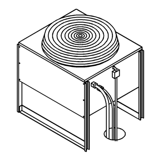
Installation References Section 2 Make the following calculations to make sure the line CALCULATING REMOTE CONDENSER set layout is within specifications. INSTALLATION DISTANCES 1. Insert the measured rise into the formula below. Line Set Length Multiply by 1.7 to get the calculated rise. The maximum length is 100’... - Page 26 Section 2 Installation References SINGLE CIRCUIT REMOTE CONDENSER ELECTRICAL DISCONNECT DISCHARGE LINE LIQUID LINE NOTE: BORE A 2.5” DIAMETER HOLE IN THE ROOF OR WALL FOR TUBING. SEAL WITH TAR OR PITCH. SLOPE TO PREVENT ENTRANCE OF MOISTURE ELECTRICAL DISCONNECT MACHINE ELECTRICAL SUPPLY...
-
Page 27: Usage With Non-Manitowoc Multi-Circuit Condensers
Any remote condenser connected to a Manitowoc when used with a Manitowoc remote condenser. J-model ice machine must have a head pressure 5. Manitowoc ice machines are UL listed with control valve (P/N 836809-3), available from Manitowoc condensers only. Manitowoc distributors, installed on the condenser 6. -
Page 28: Internal Condenser Volume
Section 2 Installation References INTERNAL CONDENSER VOLUME REFRIGERANT CHARGE The multi-circuit condenser internal volume must not Remote ice machines have the serial plate refrigerant be less, nor greater, than that used by Manitowoc. charge (total system charge) located in the ice maker section. - Page 29 Installation References Section 2 THIS PAGE INTENTIONALLY LEFT BLANK 2-18...
-
Page 30: Section 3 - Maintenance
Section 3 Maintenance Section 3 Maintenance Component Identification CONDENSER FAN (AIR-COOLED MODELS) HOT GAS VALVE CONDENSER CONDENSER WATER REGULATING VALVE REMOTE COUPLINGS WATER DUMP VALVE WATER COOLED COMPRESSOR WATER MODEL DRAIN CONDENSER HOSE SV1206 ICE THICKNESS DISTRIBUTION PROBE EVAPORATOR TUBE HIGH PRESSURE CUTOUT/ MANUAL RESET ICE/OFF/CLEAN... -
Page 31: Operational Checks
Maintenance Section 3 Operational Checks Manitowoc ice machines are factory-operated and B. Raise or lower the float valve assembly as adjusted before shipment. Normally, new installations necessary, then tighten the screws. do not require any adjustment. C. If further adjustment is required, carefully... -
Page 32: Cleaning The Condenser
Section 3 Maintenance Cleaning the Condenser 3. Shine a flashlight through the condenser to check WARNING for dirt between the fins. If dirt remains: Disconnect electric power to the ice machine and A. Blow compressed air through the condenser the remote condenser at the electric service switch fins from the inside. -
Page 33: Water-Cooled Condenser And Water Regulating Valve
Maintenance Section 3 If the ice machine is experiencing any of these WATER-COOLED CONDENSER AND symptoms, the water-cooled condenser and water WATER REGULATING VALVE Symptoms of restrictions in the condenser water regulating valve may require cleaning due to scale circuit include: build-up. -
Page 34: Interior Cleaning And Sanitizing General
Cleaning System). If required, an extremely dirty ice flow over the evaporator. machine may be take apart for cleaning and sanitizing. Step 4 Add the proper amount of Manitowoc Ice Machine Cleaner to the water trough. CAUTION Model Amount of Cleaner... -
Page 35: Procedure To Cancela Self-Cleaning Or Sanitizing Cycle After It Has Started
AFTER IT HAS STARTED If less than 45 seconds into cycle: Step 4 Add the proper amount of Manitowoc Ice Machine Sanitizer to the water trough. Move the toggle switch to the OFF position. The cycle is now canceled. - Page 36 Section 3 Maintenance AUCS ACCESSORY MANUAL START OPERATION This accessory monitors ice making cycles and Step 1 Set the toggle switch to the OFF position after initiates self-cleaning (or sanitizing) procedures ice falls from the evaporator at the end of a Harvest cycle.
-
Page 37: Removal Of Parts For Cleaning/Sanitizing
Maintenance Section 3 3. Soak the removed parts in a properly mixed REMOVAL OF PARTS FOR solution. CLEANING/SANITIZING 1. Turn off the water supply to the ice machine at Solution Type Water Mixed With the water service valve. Cleaner 1 gal. (4 l) 16 oz (500 ml) cleaner Sanitizer 4 gal. - Page 38 Section 3 Maintenance Follow the procedure below to remove the dump WATER DUMP VALVE The water dump valve normally does not require valve. removal for cleaning. To determine if removal is WARNING necessary: 1. Locate the water dump valve. Disconnect the electric power to the ice machine at 2.
- Page 39 Maintenance Section 3 NOTE: During cleaning, do not stretch, damage or WATER PUMP remove the spring from the plunger. If it is removed, WARNING slide the spring’s flared end into the plunger’s slotted top opening until the spring contacts the plunger Disconnect the electric power to the ice machine at spring stop.
- Page 40 Section 3 Maintenance ICE THICKNESS PROBE WATER TROUGH 1. Compress the side of the ice thickness probe near Water trough removal varies slightly by model. The the top hinge pin and remove it from the bracket. following procedure is typical. 1.
- Page 41 Maintenance Section 3 FLOAT VALVE WATER CURTAIN 1. Turn off the water supply to the ice machine at 1. Gently flex the curtain in the center and remove it the water service valve. from the right side. 2. Turn the splash shield counterclockwise one or two turns.
- Page 42 Section 3 Maintenance 4. Disassemble for cleaning. WATER DISTRIBUTION TUBE 1. Disconnect the water hose from the distribution INNER TUBE tube. THUMBSCREW DISTRIBUTION TUBE INNER TUBE THUMBSCREW KEYWAY LOCATING PIN LOCATING HOLE SV1211 SV1210 Water Distribution Tube Removal Water Distribution Tube Disassembly 2.
-
Page 43: Water Treatment/Filtration
Maintenance Section 3 Water Treatment/Filtration Local water conditions may require the installation of 3. Unscrew the housing from the cap. a water treatment system to inhibit scale formation, 4. Remove the used filter cartridge from the housing filter out sediment, and remove chlorine taste and and discard it. -
Page 44: Removal From Service/Winterization General
Section 3 Maintenance Removal from Service/Winterization GENERAL WATER-COOLED ICE MACHINES Special precautions must be taken if the ice machine 1. Perform steps 1-6 under “Self-Contained Air- is to be removed from service for an extended period Cooled Ice Machines.” 2. Disconnect the incoming water and drain lines of time or exposed to ambient temperatures of 32°F from the water-cooled condenser. - Page 45 Maintenance Section 3 THIS PAGE INTENTIONALLY LEFT BLANK 3-16...
-
Page 46: Section 4 - Ice Machine Sequence Of Operation
Section 4 Ice Machine Sequence of Operation Section 4 Basic Ice Machine Sequence of Operation Self-Contained Air- and Water-Cooled J200/J250/J320/J420/J450/J600/J800/J1000/J1300/J1800 INITIAL START-UP OR FREEZE SEQUENCE START-UP AFTER AUTOMATIC SHUT-OFF 3. Prechill The compressor is on for 30 seconds prior to water 1. -
Page 47: Harvest Cycle
Ice Machine Sequence of Operation Section 4 HARVEST SEQUENCE AUTOMATIC SHUT-OFF 5. Water Purge 7. Automatic Shut-Off The water pump continues to run and the water dump When the storage bin is full at the end of a harvest valve energizes for 45 seconds, to purge the water in sequence, the sheet of cubes fails to clear the water the sump trough. - Page 48 Section 4 Ice Machine Sequence of Operation Remote J450/J600/J800/J1000/J1300/J1800 INITIAL START-UP OR FREEZE SEQUENCE START-UP AFTER AUTOMATIC SHUT-OFF 3. Prechill 1. Water Purge The compressor is on for 30 seconds prior to water Before the compressor starts, the water pump and flow, to prechill the evaporator.
- Page 49 Ice Machine Sequence of Operation Section 4 HARVEST SEQUENCE AUTOMATIC SHUT-OFF 5. Water Purge 7. Automatic Shut-Off The water pump continues to run and the water dump When the storage bin is full at the end of a harvest valve energizes for 45 seconds, to purge the water in sequence, the sheet of cubes fails to clear the water the sump trough.
- Page 50 Section 5 Water System Ice Making Sequence of Operation Section 5 Water System Ice Making Sequence of Operation NOTE: The sequence of operation is the same for FREEZE CYCLE self-contained and remote models. 2. To pre-chill the evaporator, there is no water flow over the evaporator for the first 30 seconds of the INITIAL START-UP OR freeze cycle.
- Page 51 Water System Ice Making Sequence of Operation Section 5 NOTE: New style control boards have an adjustable HARVEST CYCLE 4. The water pump and water dump solenoid are water purge in the harvest cycle. This permits a 0 energized for 45 seconds to purge the water from (off), 15, 30 or 45 second purge cycle.
-
Page 52: Section 6 - Electrical System
Section 6 Electrical System Section 6 Electrical System Energized Parts Charts SELF-CONTAINED AIR- AND WATER-COOLED MODELS Ice Making Control Board Relays Contactor Sequence Length Water Water Hot Gas Contactor Condenser Dump Compressor Time Operation Pump Valve Coil Fan Motor Valve Start-Up 45 Seconds 1. -
Page 53: Remote Models
Electrical System Section 6 REMOTE MODELS Ice Making Control Board Relays Contactor Sequence Length Water Water Condenser Hot Gas Contactor Dump Compressor Time Operation Pump Fan Motor Valve Coil Valve Liquid Line Solenoid Solenoid Start-Up 45 Seconds 1. Water Purge 2. -
Page 54: Wiring Diagram Sequence Of Operation
Section 6 Electrical System Wiring Diagram Sequence of Operation SELF-CONTAINED MODELS SEE SERIAL PLATE FOR VOLTAGE L2 (N) Initial Start-Up or Start-Up After TB32 (55) TB35 (61) Automatic Shut-Off (60) HIGH (77) PRESSURE CUTOUT HOT GAS (80) 1. WATER PURGE SOLENOID (76) (75) -
Page 55: Electrical System
Electrical System Section 6 Initial Start-Up Or Start-Up After SEE SERIAL PLATE FOR VOLTAGE L2 (N) Automatic Shut-Off (cont.) TB32 (55) 2. REFRIGERATION SYSTEM TB35 (61) (60) HIGH START-UP (77) PRESSURE CUTOUT HOT GAS (80) SOLENOID The compressor starts after the 45-second (76) (75) TB30... - Page 56 Section 6 Electrical System Freeze Sequence SEE SERIAL PLATE FOR VOLTAGE L2 (N) 3. PRE-CHILL TB32 (55) To pre-chill the evaporator, the TB35 (61) (60) HIGH compressor runs for 30 seconds prior to (77) PRESSURE CUTOUT HOT GAS (80) SOLENOID water flow.
- Page 57 Electrical System Section 6 Freeze Sequence (cont.) SEE SERIAL PLATE FOR VOLTAGE L2 (N) 4. FREEZE TB32 (55) The water pump starts after the 30-second TB35 (61) (60) HIGH pre-chill. An even flow of water is (77) PRESSURE CUTOUT HOT GAS (80) directed across the evaporator and into SOLENOID...
- Page 58 Section 6 Electrical System Harvest Sequence SEE SERIAL PLATE FOR VOLTAGE L2 (N) 5. WATER PURGE TB32 (55) The water pump continues to run as the TB35 (61) (60) HIGH water dump valve energizes for 45 (77) PRESSURE CUTOUT HOT GAS (80) SOLENOID seconds to purge the water from the water...
- Page 59 Electrical System Section 6 Harvest Sequence (cont.) SEE SERIAL PLATE FOR VOLTAGE L2 (N) 6. HARVEST TB32 (55) The hot gas valve(s) remains open, TB35 (61) (60) HIGH allowing refrigerant gas to warm the (77) PRESSURE CUTOUT HOT GAS (80) SOLENOID evaporator.
- Page 60 Section 6 Electrical System 7. Automatic Shut-Off SEE SERIAL PLATE FOR VOLTAGE L2 (N) If the storage bin is full at the end of a TB32 (55) harvest cycle, the sheet of cubes fails to TB35 (61) (60) HIGH clear the water curtain and holds it open. (77) PRESSURE CUTOUT...
-
Page 61: Remote Models
Electrical System Section 6 REMOTE MODELS SEE SERIAL PLATE FOR VOLTAGE Initial Start-Up Or Start-Up After L2 (N) Automatic Shut-Off SOLENOID TB32 (55) (78) (79) TB35 1. WATER PURGE (61) (60) HIGH Before the compressor starts, the water PRESSURE (71) CUT-OUT (80) HOT GAS... - Page 62 Section 6 Electrical System Initial Start-Up Or Start-Up After SEE SERIAL PLATE FOR VOLTAGE L2 (N) Automatic Shut-Off (cont.) SOLENOID TB32 (55) 2. REFRIGERATION SYSTEM (78) (79) TB35 (61) START-UP HIGH (60) PRESSURE (71) CUT-OUT (80) HOT GAS The compressor, remote condenser fan SOLENOID (76) (75)
- Page 63 Electrical System Section 6 SEE SERIAL PLATE FOR VOLTAGE Freeze Sequence L2 (N) 3. PRE-CHILL SOLENOID TB32 (55) (78) (79) TB35 (61) To pre-chill the evaporator, the (60) HIGH PRESSURE (71) compressor runs for 30 seconds prior to CUT-OUT (80) HOT GAS SOLENOID water flow.
- Page 64 Section 6 Electrical System SEE SERIAL PLATE FOR VOLTAGE Freeze Sequence (cont.) L2 (N) SOLENOID 4. FREEZE TB32 (55) (78) (79) TB35 (61) The water pump starts after the 30-second (60) HIGH PRESSURE (71) pre-chill. An even flow of water is CUT-OUT (80) HOT GAS...
- Page 65 Electrical System Section 6 SEE SERIAL PLATE FOR VOLTAGE Harvest Sequence L2 (N) 5. WATER PURGE SOLENOID TB32 (55) (78) (79) TB35 The water pump continues to run as the (61) (60) HIGH PRESSURE (71) water dump valve energizes for 45 CUT-OUT (80) HOT GAS...
- Page 66 Section 6 Electrical System SEE SERIAL PLATE FOR VOLTAGE Harvest Sequence (cont.) L2 (N) SOLENOID 6. HARVEST TB32 (55) (78) (79) TB35 (61) The hot gas valve(s) and HPR solenoid HIGH (60) PRESSURE (71) valve remain open, allowing refrigerant CUT-OUT (80) HOT GAS SOLENOID...
- Page 67 Electrical System Section 6 SEE SERIAL PLATE FOR VOLTAGE 7. Automatic Shut-Off L2 (N) If the storage bin is full at the end of a SOLENOID TB32 (55) (78) (79) TB35 harvest cycle, the sheet of cubes fails to (61) (60) HIGH clear the water curtain and holds it open.
-
Page 68: Wiring Diagrams
Section 6 Electrical System Wiring Diagrams The following pages contain electrical wiring diagrams. Be sure you are referring to the correct diagram for the ice machine which you are servicing. WARNING Always disconnect power before working on electrical circuitry. WIRING DIAGRAM LEGEND The following symbols are used on all of the wiring diagrams: Internal Compressor Overload (Some models have external compressor overloads) -
Page 69: Old Style Self-Contained - J200/J250/J320 - 1 Phase
Electrical System Section 6 OLD STYLE SELF-CONTAINED - J200/J250/J320 - 1 PHASE CAUTION: DISCONNECT POWER BEFORE SEE SERIAL PLATE FOR VOLTAGE WORKING ON ELECTRICAL CIRCUITRY. L2 (N) NOTE: DIAGRAM SHOWN DURING FREEZE CYCLE. (61) (60) TB32 (55) (77) TB35 HOT GAS... -
Page 70: Old Style Self-Contained - J420/J450/J600/J800/J1000 - 1 Phase
Section 6 Electrical System OLD STYLE SELF-CONTAINED - J420/J450/J600/J800/J1000 - 1 PHASE CAUTION: DISCONNECT POWER BEFORE WORKING ON ELECTRICAL CIRCUITRY. SEE SERIAL PLATE FOR VOLTAGE NOTE: DIAGRAM SHOWN DURING FREEZE CYCLE. L2 (N) TB32 (55) TB35 (61) (60) HIGH (77) PRESSUR E CUT- HOT GAS... -
Page 71: Old Style Self-Contained - J800/J1000 - 3 Phase
Electrical System Section 6 OLD STYLE SELF-CONTAINED - J800/J1000 - 3 PHASE CAUTION: DISCONNECT POWER BEFORE WORKING ON ELECTRICAL CIRCUITRY. NOTE: DIAGRAM SHOWN DURING FREEZE CYCLE. SEE SERIAL PLATE FOR VOLTAGE TB32 TB35 (61) (55) (60) HIGH PRESSUR (77) E CUT- HOT GAS (80) SOLENOID... -
Page 72: Old Style Self-Contained - J1300/J1800 - 1 Phase
Section 6 Electrical System OLD STYLE SELF-CONTAINED - J1300/J1800 - 1 PHASE CAUTION: DISCONNECT POWER BEFORE WORKING ON ELECTRICAL CIRCUITRY. SEE SERIAL PLATE FOR VOLTAGE L2 (N) NOTE: DIAGRAM SHOWN DURING FREEZE CYCLE. RH HOT TB32 (55) (88) (87) TB35 (61) (60) HIGH... -
Page 73: Old Style Self-Contained - J1300/J1800 - 3 Phase
Electrical System Section 6 OLD STYLE SELF-CONTAINED - J1300/J1800 - 3 PHASE SEE SERIAL PLATE FOR VOLTAGE CAUTION: DISCONNECT POWER BEFORE WORKING ON ELECTRICAL CIRCUITRY. NOTE: DIAGRAM SHOWN DURING FREEZE CYCLE. RH HOT TB32 (88) (87) TB35 (61) N - 50HZ (60) HIGH (77) -
Page 74: Old Style Remote - J450/J600/J800/J1000 - 1 Phase
Section 6 Electrical System OLD STYLE REMOTE - J450/J600/J800/J1000 - 1 PHASE CAUTION: DISCONNECT POWER BEFORE WORKING ON ELECTRICAL CIRCUITRY. SEE SERIAL PLATE FOR VOLTAGE L2 (N) NOTE: DIAGRAM SHOWN DURING FREEZE CYCLE. SOLENOID TB32 (55) (78) (79) TB35 (61) (60) HIGH (77) -
Page 75: Old Style Remote - J800/J1000 - 3 Phase
Electrical System Section 6 OLD STYLE REMOTE - J800/J1000 - 3 PHASE SEE SERIAL PLATE FOR VOLTAGE CAUTION: DISCONNECT POWER BEFORE WORKING ON ELECTRICAL CIRCUITRY. NOTE: DIAGRAM SHOWN DURING FREEZE CYCLE. SOLENOID TB32 (78) TB35 (61) (79) HIGH (60) PRESSUR (77) E CUT- HOT GAS... -
Page 76: Old Style Remote - J1300/J1800 - 1 Phase
Section 6 Electrical System OLD STYLE REMOTE - J1300/J1800 - 1 PHASE CAUTION: DISCONNECT POWER BEFORE SEE SERIAL PLATE FOR VOLTAGE WORKING ON ELECTRICAL CIRCUITRY. L2 (N) NOTE: DIAGRAM SHOWN DURING FREEZE CYCLE. SOLENOID (78) (79) TB32 (55) RH HOT TB35 (61) (88) -
Page 77: Old Style Remote - J1300/J1800 - 3 Phase
Electrical System Section 6 OLD STYLE REMOTE - J1300/J1800 - 3 PHASE CAUTION: DISCONNECT POWER BEFORE WORKING ON ELECTRICAL CIRCUITRY. SEE SERIAL PLATE FOR VOLTAGE N - 50HZ NOTE: DIAGRAM SHOWN DURING FREEZE CYCLE. ONLY SOLENOID (78) (79) TB32 RH HOT TB35 (88) (87) -
Page 78: New Style Self-Contained - J200/J250/J320 - 1 Phase
Section 6 Electrical System NEW STYLE SELF-CONTAINED - J200/J250/J320 - 1 PHASE CAUTION: DISCONNECT POWER BEFORE WORKING ON ELECTRICAL CIRCUITRY. SEE SERIAL PLATE FOR VOLTAGE NOTE: DIAGRAM SHOWN DURING FREEZE CYCLE. L2 (N) (61) (60) TB32 (55) (77) TB35 HOT GAS... -
Page 79: New Style Self-Contained - J420/J450/J600/J800/J1000 - 1 Phase
Electrical System Section 6 NEW STYLE SELF-CONTAINED - J420/J450/J600/J800/J1000 - 1 PHASE CAUTION: DISCONNECT POWER BEFORE WORKING ON ELECTRICAL CIRCUITRY. SEE SERIAL PLATE FOR VOLTAGE NOTE: DIAGRAM SHOWN DURING FREEZE CYCLE. L2 (N) TB32 (55) TB35 (61) (60) HIGH (77) PRESSUR E CUT- HOT GAS... -
Page 80: New Style Self-Contained - J800/J1000 - 3 Phase
Section 6 Electrical System NEW STYLE SELF-CONTAINED - J800/J1000 - 3 PHASE CAUTION: DISCONNECT POWER BEFORE SEE SERIAL PLATE FOR VOLTAGE WORKING ON ELECTRICAL CIRCUITRY. NOTE: DIAGRAM SHOWN DURING FREEZE CYCLE. TB32 TB35 (61) (55) (60) HIGH (77) PRESSUR E CUT- HOT GAS (80) SOLENOID... -
Page 81: New Style Self-Contained - J1300/J1800 - 1 Phase
Electrical System Section 6 NEW STYLE SELF-CONTAINED - J1300/J1800 - 1 PHASE CAUTION: DISCONNECT POWER BEFORE WORKING ON ELECTRICAL CIRCUITRY. SEE SERIAL PLATE FOR VOLTAGE L2 (N) NOTE: DIAGRAM SHOWN DURING FREEZE CYCLE. RH HOT TB32 (55) (88) (87) TB35 (61) (60) HIGH... -
Page 82: New Style Self-Contained - J1300/J1800 - 3 Phase
Section 6 Electrical System NEW STYLE SELF-CONTAINED - J1300/J1800 - 3 PHASE CAUTION: DISCONNECT POWER BEFORE WORKING ON ELECTRICAL CIRCUITRY. SEE SERIAL PLATE FOR VOLTAGE NOTE: DIAGRAM SHOWN DURING FREEZE CYCLE. RH HOT TB32 (88) (87) TB35 (61) N - 50HZ (60) HIGH (77) -
Page 83: New Style Remote - J450/J600/J800/J1000 - 1 Phase
Electrical System Section 6 NEW STYLE REMOTE - J450/J600/J800/J1000 - 1 PHASE CAUTION: DISCONNECT POWER BEFORE WORKING ON ELECTRICAL CIRCUITRY. SEE SERIAL PLATE FOR VOLTAGE L2 (N) NOTE: DIAGRAM SHOWN DURING FREEZE CYCLE. SOLENOID TB32 (55) (78) (79) TB35 (61) (60) HIGH (77) -
Page 84: New Style Remote - J800/J1000 - 3 Phase
Section 6 Electrical System NEW STYLE REMOTE - J800/J1000 - 3 PHASE SEE SERIAL PLATE FOR VOLTAGE CAUTION: DISCONNECT POWER BEFORE WORKING ON ELECTRICAL CIRCUITRY. NOTE: DIAGRAM SHOWN DURING FREEZE CYCLE. SOLENOID TB32 (78) TB35 (61) (79) HIGH (60) PRESSUR (77) E CUT- HOT GAS... -
Page 85: New Style Remote - J1300/J1800 - 1 Phase
Electrical System Section 6 NEW STYLE REMOTE - J1300/J1800 - 1 PHASE CAUTION: DISCONNECT POWER BEFORE WORKING ON ELECTRICAL CIRCUITRY. NOTE: DIAGRAM SHOWN DURING FREEZE CYCLE. SEE SERIAL PLATE FOR VOLTAGE L2 (N) SOLENOID (78) (79) TB32 (55) RH HOT TB35 (61) (88) -
Page 86: New Style Remote - J1300/J1800 - 3 Phase
Section 6 Electrical System NEW STYLE REMOTE - J1300/J1800 - 3 PHASE CAUTION: DISCONNECT POWER BEFORE WORKING ON ELECTRICAL CIRCUITRY. NOTE: DIAGRAM SHOWN DURING FREEZE CYCLE. SEE SERIAL PLATE FOR VOLTAGE N - 50HZ ONLY SOLENOID (78) (79) TB32 RH HOT TB35 (88) (87) -
Page 87: Component Specifications And Diagnostics
Electrical System Section 6 Component Specifications and Diagnostics FUSES BIN SWITCH Function Function The control board fuse(s) stops ice machine operation Bin switch operation is controlled by movement of if electrical components fail causing high amp draw. the water curtain. The bin switch has two main functions: Specifications 1. - Page 88 Section 6 Electrical System Water Curtain Removal Notes Check Procedure 1. Set the toggle switch to OFF. The water curtain must be on (bin switch closed) to 2. Watch the bin switch light on the control board. start ice making. While a freeze cycle is in progress, 3.
-
Page 89: Compressor Electrical Diagnostics
Electrical System Section 6 Determine if the Compressor is Seized COMPRESSOR ELECTRICAL DIAGNOSTICS Check the amp draw while the compressor is trying to start. The compressor will not start or will trip repeatedly on overload. COMPRESSOR DRAWING LOCKED ROTOR The two likely causes of this are: Check Resistance (Ohm) Values •... -
Page 90: Ptcr Diagnostics
Section 6 Electrical System Compressor Start Sequence PTCR DIAGNOSTICS PTCR’s provide additional starting torque by increasing the current in the auxiliary (start) winding What is a PTCR? during starting. The PTCR is wired across the run A PTCR (or Positive Temperature Coefficient capacitor (in series with the start winding). - Page 91 Electrical System Section 6 J-Model Automatic Shut-Off and Restart When the storage bin is full at the end of a harvest CONTACTOR CONTACTS RUN CAPACITOR cycle, the sheet of cubes fails to clear the water curtain and will hold it open. After the water curtain is held open for 7 seconds, the ice machine shuts off.
- Page 92 TO START THE COMPRESSOR too low. The PTCR must be cooled before attempting to start Manitowoc ice machines are rated at ±10% of the compressor, otherwise the high starting torque nameplate voltage at compressor start-up. (Ex: An may not last long enough.
- Page 93 If the resistance falls outside of the acceptable range, replace it. SV1541 Room Manitowoc Cera-Mite Model Temperature Manitowoc PTCR 8504913 Part Number Part Number Resistance J200 J250 J320 8505003 305C20 22-50 Ohms J420 J450 J600 J800 8504993 305C19 18-40 Ohms J1000...
-
Page 94: Discharge Line Thermistor
Section 6 Electrical System Verify that the thermistor resistance is accurate and DISCHARGE LINE THERMISTOR corresponding to the high and low temperature ranges. NOTE: The discharge line thermistor is not used on 1. Disconnect the thermistor from terminals 1A and later production J-model ice machines. -
Page 95: Ice/Off/Clean Toggle Switch
Electrical System Section 6 Temperature/Resistance Chart ICE/OFF/CLEAN TOGGLE SWITCH As the temperature rises at the thermistor block, the Function resistance drops. The switch is used to place the ice machine in ICE, Important OFF or CLEAN mode of operation. If the ohm meter reads “OL”, check the scale Specifications setting on the meter before assuming the thermistor Double-pole, double-throw switch. -
Page 96: Control Board Relays
Section 6 Electrical System For example, a service technician turns the toggle CONTROL BOARD RELAYS switch OFF (relay contact open) and unplugs the water pump (component disconnected). The service Function technician places the voltmeter leads into the water The control board relays energize and de-energize pump plug (taking voltage through open contacts system components. -
Page 97: Electronic Control Board (Old Style)
Electrical System Section 6 ELECTRONIC CONTROL BOARD (OLD STYLE) AC LINE VOLTAGE ELECTRICAL PLUG (NUMBERS MARKED ON WIRES) PRIMARY POWER SUPPLY N 115V 208-230V MAIN FUSE (7A) TRANSFORMER FUSE (.125A - 60HZ) AUTOMATIC CLEANING SYSTEM (.100A - 50HZ) (AuCS) ACCESSORY PLUG HARVEST LIGHT/ ICE THICKNESS PROBE SAFETY LIMIT CODE LIGHT... -
Page 98: Electronic Control Board (New Style)
Section 6 Electrical System ELECTRONIC CONTROL BOARD (NEW STYLE) AC LINE VOLTAGE ELECTRICAL PLUG (NUMBERS MARKED ON WIRES) PRIMARY POWER SUPPLY N 115V 208-230V CLEAN LIGHT -- YELLOW MAIN FUSE (7A) LIGHT NOT USED -- GREEN BIN SWITCH LIGHT -- GREEN AUTOMATIC CLEANING SYSTEM HARVEST LIGHT/ (AuCS) - Page 99 Electrical System Section 6 HARVEST/SAFETY LIMIT LIGHT Control Board This light’s primary function is to be on as water contacts the ice thickness probe during the freeze HARVEST INITIATION cycle and remain on throughout the entire harvest (ICE THICKNESS PROBE) cycle.
- Page 100 Section 6 Electrical System SAFETY LIMITS Water Curtain Removal In addition to standard safety controls, such as the high pressure cut-out, the control board has built-in The water curtain must be on (bin switch closed) to safety limits. Old style control boards have four start ice making.
-
Page 101: Ice Thickness Probe (Harvest Initiation) General
Electrical System Section 6 Ice Thickness Probe (Harvest Initiation) GENERAL FREEZE TIME LOCK-IN FEATURE The ice thickness probe has been changed from a dual Since original production, the ice machine control probe to a single probe. This eliminates the system has incorporated a freeze time lock-in feature. possibility of scale or slime forming between the This prevents the ice machine from short cycling in probes and causing a premature harvest cycle. -
Page 102: Diagnosing Probe Control Circuitry
Section 6 Electrical System DIAGNOSING PROBE CONTROL CIRCUITRY Ice Machine Cycles Into Harvest Before Water Contact with Probe 1. Disconnect the ice thickness probe from the control board. 2. Bypass the freeze time lock-in feature by moving the ICE/OFF /CLEAN switch to OFF and back to ICE. 3. -
Page 103: Ice Machine Does Not Cycle Into Harvest When Water Contacts Probe
Electrical System Section 6 Ice Machine Does Not Cycle Into Harvest When Water Contacts Probe 1. Bypass the freeze time lock-in feature by moving the ICE/OFF/CLEAN switch to OFF and back to ICE. 2. Clip the leads of a jumper wire onto the ice thickness probe to try to initiate a harvest cycle. 3. -
Page 104: Diagnosing Ice Machine That Will Not Run
Section 6 Electrical System Diagnosing Ice Machine That Will Not Run WARNING High (line) voltage is applied to the control board (terminals #55 and #56) at all times. Removing control board fuses or moving the toggle switch to OFF will not remove the power supplied to the control board. - Page 105 Electrical System Section 6 THIS PAGE INTENTIONALLY LEFT BLANK 6-54...
-
Page 106: Section 7 - Refrigeration System
HIGH PRESSURE LIQUID LOW PRESSURE LIQUID LOW PRESSURE VAPOR SV1569 Self-Contained Prechill and Freeze Cycle (Models J250/J320/J420/J450/J600/J800/J1000) Prechill Refrigeration Sequence Freeze Cycle Refrigeration Sequence No water flows over the evaporator during the The refrigerant absorbs heat from water running over prechill. - Page 107 HIGH PRESSURE LIQUID LOW PRESSURE LIQUID LOW PRESSURE VAPOR SV1570 Self-Contained Harvest Cycle (Models J250/J320/J420/J450/J600/J800/J1000) Harvest Cycle Refrigeration Sequence Hot gas flows through the energized hot gas valve, heating the evaporator. The hot gas valve is sized to allow the proper amount of refrigerant into the evaporator.
-
Page 108: Remote Models
Section 7 Refrigeration System REMOTE MODELS EVAPORATOR HEAT EXCHANGER EXPANSION VALVE STRAINER COMPRESSOR HOT GAS SOLENOID VALVE LIQUID LINE SOLENOID CHECK VALVE REMOTE VALVE CONDENSER HARVEST PRESSURE HEAD REGULATING PRESSURE HARVEST VALVE CONTROL PRESSURE VALVE REGULATING DRIER SOLENOID VALVE CHECK VALVE RECEIVER SERVICE VALVE RECEIVER... - Page 109 Refrigeration System Section 7 EVAPORATOR HEAT EXCHANGER EXPANSION VALVE STRAINER COMPRESSOR HOT GAS SOLENOID VALVE LIQUID LINE CHECK VALVE SOLENOID REMOTE VALVE CONDENSER HARVEST PRESSURE HEAD REGULATING PRESSURE HARVEST VALVE CONTROL PRESSURE VALVE REGULATING DRIER SOLENOID VALVE CHECK VALVE RECEIVER SERVICE VALVE RECEIVER HIGH PRESSURE LIQUID...
- Page 110 Section 7 Refrigeration System EVAPORATOR HEAT EXCHANGER EXPANSION VALVE STRAINER COMPRESSOR HOT GAS SOLENOID VALVE LIQUID LINE CHECK VALVE SOLENOID REMOTE VALVE CONDENSER HARVEST HEAD PRESSURE PRESSURE REGULATING HARVEST CONTROL VALVE PRESSURE VALVE DRIER REGULATING SOLENOID VALVE CHECK VALVE RECEIVER SERVICE VALVE RECEIVER LIQUID/VAPOR EQUALIZED TO...
-
Page 111: J1300/J1800 Refrigeration Tubing Schematics
Refrigeration System Section 7 J1300/J1800 REFRIGERATION TUBING SCHEMATICS EVAPORATOR HEAT EXCHANGE EXPANSION EXPANSION VALVE VALVE HOT GAS SOLENOID VALVES COMPRESSOR STRAINER AIR OR WATER COOLED CONDENSER DRIER CHECK VALVE (J1800 AIR COOLED ONLY) RECEIVER J1300/J1800 Self-Contained Air- or Water-Cooled Models SV1512 NOTE: The refrigeration sequence for self-contained dual expansion valve ice machines is identical to self-... - Page 112 Section 7 Refrigeration System EVAPORATOR HEAT EXCHANGE EXPANSION EXPANSION VALVE VALVE LIQUID LINE SOLENOID VALVE HOT GAS SOLENOID VALVES COMPRESSOR STRAINER CHECK VALVE REMOTE CONDENSER HARVEST PRESSURE REGULATING VALVE HEAD PRESSURE DRIER CONTROL VALVE CHECK VALVE RECEIVER H.P.R. SERVICE SOLENOID VALVE VALVE RECEIVER...
-
Page 113: Operational Analysis (Diagnostics) General
Refrigeration System Section 7 Operational Analysis (Diagnostics) GENERAL 2. An ice machine that is low on charge may cause a When analyzing the refrigeration system, it is good expansion valve to starve. If a service important to understand that different refrigeration technician fails to verify the system charge, he component malfunctions may cause very similar may replace the expansion valve in error. -
Page 114: Before Beginning Service
Section 7 Refrigeration System BEFORE BEGINNING SERVICE 2. Refer to the appropriate 24 Hour Ice Production Ice machines may experience operational problems Chart. (These charts begin on page 7-31.) Use the only during certain times of the day or night. A operating conditions determined in Step 1 to find machine may function properly while it is being the published 24 ice production:... -
Page 115: Installation/Visual Inspection Checklist
Refrigeration System Section 7 INSTALLATION/VISUAL INSPECTION WATER SYSTEM CHECKLIST CHECKLIST A water-related problem often causes the same symptoms as a refrigeration system component Possible Problem Corrective Action malfunction. Ice machine is not level Level the ice machine Improper clearance Reinstall according to around top, sides and/or the Installation Manual Example: A water dump valve leaking during the... -
Page 116: Ice Formation Pattern
Section 7 Refrigeration System ICE FORMATION PATTERN 2. Extremely Thin at Evaporator Outlet Evaporator ice formation pattern analysis is helpful in There is no ice, or a considerable lack of ice ice machine diagnostics. formation on the top of the evaporator (tubing outlet). Analyzing the ice formation pattern alone cannot Examples: No ice at all on the top of the evaporator, diagnose an ice machine malfunction. - Page 117 Refrigeration System Section 7 3. Extremely Thin at Evaporator Inlet 5. No Ice Formation There is no ice, or a considerable lack of ice The ice machine operates for an extended period, but formation on the bottom of the evaporator (tubing there is no ice formation at all on the evaporator.
-
Page 118: Safety Limits
Section 7 Refrigeration System SAFETY LIMITS Analyzing Why Safety Limits May Stop the Ice Machine General According to the refrigeration industry, a high In addition to standard safety controls, such as high percentage of compressors fail as a result of external pressure cut-out, the control board has four built in causes. - Page 119 Refrigeration System Section 7 Safety Limit #1 Freeze time exceeds 60 minutes for 3 consecutive freeze cycles. Possible Cause Check/Correct Improper installation • See “Installation/Visual Inspection Checklist” on page 7-10 Water system • Low water pressure (20 psi min.) • High water pressure (80 psi max.) •...
- Page 120 Section 7 Refrigeration System Safety Limit #2 Harvest time exceeds 3.5 minutes for 3 consecutive harvest cycles. Possible Cause Check/Correct Improper installation • See “Installation/Visual Inspection Checklist” on page 7-10 Water system • Water area (evaporator) dirty • Dirty/defective water dump valve •...
- Page 121 Refrigeration System Section 7 Safety Limit #3 Compressor discharge temperature fell below 85°F/29.4°C for 3 consecutive harvest cycles. Possible Cause Check/Correct Improper installation • See “Installation/Visual Inspection Checklist” on page 7-10 Ice thickness probe • Check thickness setting Water system - insufficient •...
-
Page 122: Hot Gas Valve Temperature Check
Section 7 Refrigeration System HOT GAS VALVE TEMPERATURE CHECK Important Feeling the hot gas valve outlet or across the hot General gas valve itself will not work for this comparison. A hot gas valve requires a critical orifice size. This meters the amount of hot gas flowing into the The hot gas valve outlet is on the suction side (cool evaporator during the harvest cycle. -
Page 123: Single Expansion Valve Ice Machines Comparing Evaporator Inlet And Outlet Temperatures
Refrigeration System Section 7 SINGLE EXPANSION VALVE ICE MACHINES Use this procedure to document freeze cycle inlet and COMPARING EVAPORATOR outlet temperatures. INLET AND OUTLET TEMPERATURES 1. Use a quality temperature meter, capable of taking temperature readings on curved copper NOTE: This procedure will not work on the dual lines. -
Page 124: Analyzing Discharge Pressure During Freeze Or Harvest Cycle Procedure
Section 7 Refrigeration System ANALYZING DISCHARGE PRESSURE 3. Perform an actual discharge pressure check. DURING FREEZE OR HARVEST CYCLE Freeze Cycle Harvest Cycle Procedure PSIG PSIG 1. Determine the ice machine operating conditions: Beginning of Cycle __________ __________ ______ Air temp. entering condenser Middle of Cycle __________ __________... -
Page 125: Analyzing Suction Pressure During Freeze Cycle
Refrigeration System Section 7 ANALYZING SUCTION PRESSURE To analyze and identify the proper suction pressure DURING FREEZE CYCLE drop throughout the freeze cycle, compare the The suction pressure gradually drops throughout the published suction pressure to the published freeze freeze cycle. The actual suction pressure (and drop cycle time. -
Page 126: Freeze Cycle Suction Pressure High Checklist
Section 7 Refrigeration System Freeze Cycle Suction Pressure High Checklist Possible Cause Check/Correct Improper installation • See “Installation/Visual Inspection Checklist” on page 7-10 Discharge pressure • Discharge pressure is too high, and is affecting low side (See “Freeze Cycle Discharge Pressure High Checklist” on page 7-19) Improper refrigerant charge •... -
Page 127: How To Use The Refrigeration System Operational Analysis Tables
Refrigeration System Section 7 HOW TO USE THE REFRIGERATION Step 2 Enter check marks (3) in the small boxes. SYSTEM OPERATIONAL ANALYSIS TABLES Each time the actual findings of an item in the General “Operational Analysis” column matches the These tables must be used with charts, checklists and published findings on the table, enter a check mark. - Page 128 Section 7 Refrigeration System COLUMN 3 - TXV FLOODING Final Analysis Before totaling the four columns, be sure to analyze A loose or improperly mounted expansion valve bulb all detailed charts, checklists, and other references to causes the expansion valve to flood. Check bulb eliminate external causes which may make a good mounting, insulation, etc., before changing the valve.
-
Page 129: Refrigeration System Operational Analysis Tables
Hot Gas Valve Low on Charge TXV Flooding Compressor Leaking -OR- TXV Starving MANITOWOC ICE, INC. 2110 South 26th Street P.O. Box 1720 Manitowoc, WI 54221-1720 Phone: (414) 682-0161 Service Fax: (414) 683-7585 Web Site: http://www.manitowoc.com 7-24... - Page 130 Hot Gas Valve Low on Charge TXV Flooding Compressor Leaking -OR- TXV Starving MANITOWOC ICE, INC. 2110 South 26th Street P.O. Box 1720 Manitowoc, WI 54221-1720 Phone: (414) 682-0161 Service Fax: (414) 683-7585 Web Site: http://www.manitowoc.com 7-25...
-
Page 131: Remotes Only
Refrigeration System Section 7 FREEZE CYCLE REMOTES ONLY The H.P.R. system is not used during the freeze cycle. Harvest Pressure Regulating (H.P.R.) System The H.P.R. solenoid is closed (de-energized), GENERAL preventing refrigerant flow into the H.P.R. valve. The harvest pressure regulating (H.P.R.) system includes: HARVEST CYCLE 1. - Page 132 Section 7 Refrigeration System H.P.R. SYSTEM FAILURE CHART Symptoms Possible Causes Freeze The ice machine functions properly. (The H.P.R. solenoid is Cycle closed, preventing refrigerant flow into the H.P.R. valve.) Harvest The discharge pressure is low or normal and the suction Cycle pressure is low, which causes extended harvest times.
-
Page 133: Headmaster Control Valve
Refrigeration System Section 7 DIAGNOSING Headmaster Control Valve Manitowoc remote systems require headmaster 1. Determine the air temperature entering the remote condenser. control valves with special settings. Replace defective 2. Determine if the head pressure is high or low in headmaster control valves only with “original”... - Page 134 Section 7 Refrigeration System LOW ON CHARGE VERIFICATION FAN CYCLE CONTROL VS. HEADMASTER The remote ice machine requires more refrigerant A fan cycle control cannot be used in place of a charge at lower ambient temperatures than at higher headmaster. The fan cycle control is not capable of temperatures.
-
Page 135: Pressure Control Specifications And Diagnostics
Specifications Specifications Cut-out: 450 psig ±10 Model Cut-In (Close) Cut-Out (Open) Cut-in: Manual (below 300 psig to reset) J200 J250 J320 J420 250 psig ±5 200 psig ±5 J450 J600 Check Procedure J800 J1000 1. Set ICE/OFF/CLEAN switch to OFF, and reset J1300 J1800 275 psig ±5... -
Page 136: Cycle Time/24 Hour Ice Production/Refrigerant Pressure Charts J200
Section 7 Refrigeration System Cycle Time/24 Hour Ice Production/Refrigerant Pressure Charts J200 SERIES J200 SERIES WATER-COOLED SELF-CONTAINED AIR-COOLED NOTE: These characteristics may vary depending on NOTE: These characteristics may vary depending on operating conditions. operating conditions. Cycle Times Cycle Times Freeze Time + Harvest Time = Cycle Time Freeze Time + Harvest Time = Cycle Time Air Temp. -
Page 137: J250
Refrigeration System Section 7 J250 SERIES J250 SERIES WATER-COOLED SELF-CONTAINED AIR-COOLED NOTE: These characteristics may vary depending on NOTE: These characteristics may vary depending on operating conditions. operating conditions. Cycle Times Cycle Times Freeze Time + Harvest Time = Cycle Time Freeze Time + Harvest Time = Cycle Time Air Temp. -
Page 138: J320
Section 7 Refrigeration System J320 SERIES J320 SERIES WATER-COOLED SELF-CONTAINED AIR-COOLED NOTE: These characteristics may vary depending on NOTE: These characteristics may vary depending on operating conditions. operating conditions. Cycle Times Cycle Times Freeze Time + Harvest Time = Cycle Time Freeze Time + Harvest Time = Cycle Time Air Temp. -
Page 139: Operating Pressures
Refrigeration System Section 7 J420/450 SERIES J420/450 SERIES WATER-COOLED SELF-CONTAINED AIR-COOLED NOTE: These characteristics may vary depending on NOTE: These characteristics may vary depending on operating conditions. operating conditions. Cycle Times Cycle Times Freeze Time + Harvest Time = Cycle Time Freeze Time + Harvest Time = Cycle Time Air Temp. -
Page 140: J600
Section 7 Refrigeration System J450 SERIES REMOTE J600 SERIES SELF-CONTAINED AIR-COOLED NOTE: These characteristics may vary depending on NOTE: These characteristics may vary depending on operating conditions. operating conditions. Cycle Times Cycle Times Freeze Time + Harvest Time = Cycle Time Freeze Time + Harvest Time = Cycle Time Air Temp. - Page 141 Refrigeration System Section 7 J600 SERIES WATER-COOLED J600 SERIES REMOTE NOTE: These characteristics may vary depending on NOTE: These characteristics may vary depending on operating conditions. operating conditions. Cycle Times Cycle Times Freeze Time + Harvest Time = Cycle Time Freeze Time + Harvest Time = Cycle Time Air Temp.
-
Page 142: J800
Section 7 Refrigeration System J800 SERIES J800 SERIES WATER-COOLED SELF-CONTAINED AIR-COOLED NOTE: These characteristics may vary depending on NOTE: These characteristics may vary depending on operating conditions. operating conditions. Cycle Times Cycle Times Freeze Time + Harvest Time = Cycle Time Freeze Time + Harvest Time = Cycle Time Air Temp. -
Page 143: J1000
Refrigeration System Section 7 J800 SERIES REMOTE J1000 SERIES SELF-CONTAINED AIR-COOLED NOTE: These characteristics may vary depending on NOTE: These characteristics may vary depending on operating conditions. operating conditions. Cycle Times Cycle Times Freeze Time + Harvest Time = Cycle Time Freeze Time + Harvest Time = Cycle Time Air Temp. - Page 144 Section 7 Refrigeration System J1000 SERIES WATER-COOLED J1000 SERIES REMOTE NOTE: These characteristics may vary depending on NOTE: These characteristics may vary depending on operating conditions. operating conditions. Cycle Times Cycle Times Freeze Time + Harvest Time = Cycle Time Freeze Time + Harvest Time = Cycle Time Air Temp.
-
Page 145: J1300
Refrigeration System Section 7 J1300 SERIES J1300 SERIES WATER-COOLED SELF-CONTAINED AIR-COOLED NOTE: These characteristics may vary depending on NOTE: These characteristics may vary depending on operating conditions. operating conditions. Cycle Times Cycle Times Freeze Time + Harvest Time = Cycle Time Freeze Time + Harvest Time = Cycle Time Air Temp. -
Page 146: J1800
Section 7 Refrigeration System J1300 SERIES REMOTE J1800 SERIES SELF-CONTAINED AIR-COOLED NOTE: These characteristics may vary depending on NOTE: These characteristics may vary depending on operating conditions. operating conditions. Cycle Times Freeze Time + Harvest Time = Cycle Time Cycle Times Freeze Time + Harvest Time = Cycle Time Air Temp. - Page 147 Refrigeration System Section 7 J1800 SERIES WATER-COOLED J1800 SERIES REMOTE NOTE: These characteristics may vary depending on NOTE: These characteristics may vary depending on operating conditions. operating conditions. Cycle Times Cycle Times Freeze Time + Harvest Time = Cycle Time Freeze Time + Harvest Time = Cycle Time Air Temp.
- Page 148 Section 7 Refrigeration System THIS PAGE INTENTIONALLY LEFT BLANK 7-43...
-
Page 149: Refrigerant Recovery/Evacuating And Recharging
Do not purge refrigerant to the atmosphere. Capture refrigerant using recovery equipment. Follow the MANIFOLD SET manufacturer’s recommendations. OPEN OPEN Important Manitowoc Ice, Inc. assumes no responsibility for BACKSEATED BACKSEATED LOW SIDE HIGH SIDE the use of contaminated refrigerant. Damage SERVICE... - Page 150 Important valve. The charge is critical on all Manitowoc ice 3. Open the high side manifold gauge valve, and machines. Use a scale or a charging cylinder to backseat the high side service valve.
-
Page 151: Normal Remote Model Procedures
Important Manitowoc Ice, Inc. assumes no responsibility for REMOTE RECOVERY/EVACUATION the use of contaminated refrigerant. Damage 1. Place the toggle switch in the OFF position. resulting from the use of contaminated refrigerant is 2. - Page 152 Section 7 Refrigeration System HEAT EXCHANGER EVAPORATOR EXPANSION VALVE HOT GAS SOLENOID VALVES LOW SIDE SERVICE VALVE (BACKSEATED) STRAINER COMPRESSOR HARVEST PRESSURE SOLENOID CHECK VALVE HARVEST PRESSURE VALVE REGULATING VALVE LIQUID LINE HIGH SIDE SERVICE SOLENOID VALVE (BACKSEATED) DISCHARGE LINE QUICK CONNECT DRIER SCHRAEDER FITTING...
- Page 153 Refrigeration System Section 7 Remote Charging Procedures NOTE: Backseat the receiver outlet service valve after 1. Be sure the toggle switch is in the OFF position. charging is complete and before operating the ice 2. Close the vacuum pump valve, the low and high machine.
- Page 154 Section 7 Refrigeration System HEAT EXCHANGER EVAPORATOR EXPANSION VALVE HOT GAS SOLENOID VALVES LOW SIDE SERVICE VALVE (BACKSEATED) STRAINER COMPRESSOR HARVEST PRESSURE SOLENOID CHECK VALVE HARVEST PRESSURE VALVE REGULATING VALVE LIQUID LINE HIGH SIDE SERVICE SOLENOID VALVE (BACKSEATED) DISCHARGE LINE QUICK CONNECT DRIER SCHRAEDER FITTING...
-
Page 155: System Contamination Cleanup
Follow the manufacturer’s directions. Important Manitowoc Ice, Inc. assumes no responsibility for If a refrigerant test kit indicates harmful levels of the use of contaminated refrigerant. Damage contamination, or if a test kit is not available, inspect resulting from the use of contaminated refrigerant is the compressor oil. - Page 156 Section 7 Refrigeration System Mild System Contamination Cleanup Procedure Severe System Contamination Cleanup Procedure 1. Replace any failed components. 2. If the compressor is good, change the oil. 1. Remove the refrigerant charge. 3. Replace the liquid line drier. 2. Remove the compressor. 3.
-
Page 157: Replacing Pressure Controls Without Removing Refrigerant Charge
Refrigeration System Section 7 11. Follow the normal evacuation procedure, except REPLACING PRESSURE CONTROLS WITHOUT replace the evacuation step with the following: REMOVING REFRIGERANT CHARGE This procedure reduces repair time and cost. Use it Important when any of the following components require Dry nitrogen is recommended for this procedure. - Page 158 Section 7 Refrigeration System FIG. A - “PINCHING OFF” TUBING TYPICAL PRESSURE CONTROL SHOWN “PINCH-OFF” TOOL USED HERE SEE FIG. A AND FIG. B FIG. B - RE-ROUNDING TUBING SV1406 Using Pinch-Off Tool 7-53...
-
Page 159: Filter-Driers
Refrigeration System Section 7 FILTER-DRIERS TOTAL SYSTEM REFRIGERANT CHARGES The filter-driers used on Manitowoc ice machines are Important manufactured to Manitowoc specifications. Refer to the ice machine serial number tag to verify the system charge. The difference between Manitowoc driers and off-... -
Page 160: Refrigerant Definitions
Section 7 Refrigeration System Reclaim REFRIGERANT DEFINITIONS To reprocess refrigerant to new product specifications Recover (see below) by means which may include distillation. To remove refrigerant, in any condition, from a A chemical analysis of the refrigerant is required after system and store it in an external container, without processing to be sure that product specifications are necessarily testing or processing it in any way. -
Page 161: Refrigerant Re-Use Policy
• Recovered refrigerant must come from a Important “contaminant-free” system. To decide Manitowoc Ice, Inc. assumes no responsibility for whether the system is contaminant free, use of contaminated refrigerant. Damage resulting consider: from the use of contaminated, recovered, or •... -
Page 162: Hfc Refrigerant Questions And Answers
Section 7 Refrigeration System 4. Are there any special procedures required if a HFC REFRIGERANT QUESTIONS AND POE system is diagnosed with a refrigerant leak? ANSWERS Manitowoc uses R-404A and R-134A HFC For systems found with positive refrigerant system refrigerants with ozone depletion potential (ODP) pressure, no special procedures are required. - Page 163 Refrigeration System Section 7 7. Is other special equipment required to service 8. Do I have to recover HFC refrigerants? HFC refrigerants? Yes. Like other refrigerants, government regulations No. Standard refrigeration equipment such as gauges, require recovering HFC refrigerants. hoses, recovery systems, vacuum pumps, etc., are generally compatible with HFC refrigerants.
- Page 165 MANITOWOC ICE, INC. 2110 South 26th Street P.O. Box 1720 Manitowoc, WI 54221-1720 Phone: (920) 682-0161 Service Fax: (920) 683-7585 Web Site: http://www.manitowoc.com ã1997 Manitowoc Ice, Inc. Litho in U.S.A.
Need help?
Do you have a question about the J250 and is the answer not in the manual?
Questions and answers