
Related Manuals for LG LE3116D


Summary of Contents for LG LE3116D
-
Page 1: Digital Video Recorder
LE3116D/LE3108D_W/WIDE_ENG_(V1.0)_MFL30580189 DIGITAL VIDEO RECORDER OWNER’S MANUAL MODEL: LE3116D LE3108D Before connecting, operating or adjusting this product, please read this owner’s manual carefully and completely. - Page 2 Warning: Do not install this equipment in a confined CAUTION space such as a bookcase or similar unit. RISK OF ELECTRIC SHOCK Warning: Wiring methods shall be in accordance with DO NOT OPEN the National Electric Code, ANSI/NFPA 70. Warning: This is a class A product. In a domestic CAUTION: TO REDUCE THE RISK environment this product may cause radio interfer- OF ELECTRIC SHOCK...
-
Page 3: Important Safety Instructions
IMPORTANT SAFETY INSTRUCTIONS CAUTION: PLEASE READ AND OBSERVE ALL WARNINGS AND INSTRUCTIONS IN THIS OWNER’S MANUAL. AND THOSE MARKED ON THE PRODUCT. RETAIN THIS BOOKLET FOR FUTURE REFERENCE. This product has been designed and manufactured to assure personal safety. Improper use can result in elec- tric shock or fire hazard. - Page 4 Ask for an engineer’s assistance for HDD injury. replacement from your dealer. - LG Electronics is not responsible for deleted data • Check for any danger signs such as a moist floor, a caused by user mishandling. loosened or damaged power cable, or an unstable surface.
- Page 5 • Placing the system near electronic devices such as a radio or a TV may cause the product to breakdown. • Do not disassemble the product without seeking assistance from LG Electronics. • Do not place any heavy object on the system.
-
Page 6: Table Of Contents
SEARCH AND PLAYBACK ....42 Contents PLAYBACK ............42 INTRODUCTION ........7 SEARCH .............43 Functions Available During Playback ....46 Features ...............7 EXPORT ............47 Front Panel ............8 Accessories ............9 CLIENT PROGRAM ......48 Rear Panel ............10 Remote Control ..........11 PC Requirements ..........48 Basic Connection Overview ......12 Client Program Installation ......48 Connecting to the DVR ........49... -
Page 7: Introduction
Motion event recording and preview test function of motion sensitivity. • Recording image rate & quality adjustment per individual camera. • Powerful record scheduling. Model LE3116D (16 Channel) is used for the description, operation and details provided in this operating guide. -
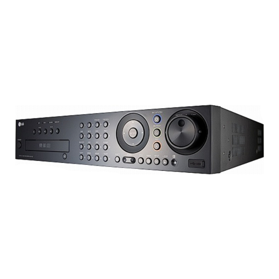
Page 8: Front Panel
Front Panel x LE3116D k l mnopq x LE3108D k l mnopq Playback Control Buttons Channel Buttons - X: Pauses playback. You can input a number with channel buttons. - m/c, .: Search the recorded images in You can also use the channel buttons for sub- reverse or skip the recorded images. -
Page 9: Accessories
1 Power Adjust iris position. Turns DVR on or off. (9) ALM.OFF Press and hold for more than 2 seconds to turn Cancels alarm activation and returns the system on or off. to the condition before the alarm was activated. Disc Tray (10/0) LOG Insert a disc here. -
Page 10: Rear Panel
Rear Panel x LE3116D f g h j k l x LE3108D f g h j k l VIDEO INPUT AUDIO INPUT Connect the camera’s video output to these Connect the audio output of an external device. BNC connectors. SPOT-OUT (BNC Type Connector) LOOP OUT Connect to spot monitor or display device. -
Page 11: Remote Control
Remote Control M/C/> MAIN Forward searches the recorded Displays the MAIN menu to set images or skips the recorded the screen mode to full, 4, 6, 8, 9 images. or 16 screens. Number Buttons (0,1-9) SPOT To select the PTZ preset number, Enter SPOT mode to allow spot ID, or channel. -
Page 12: Basic Connection Overview
HOOKUP AND SETTINGS Precautions • Depending on the camera and other equipment there are various ways to connect the unit. Please refer to the camera manual or manuals for other devices as necessary for additional connection information. • Be sure to switch off the camera before installation and connection. Basic Connection Overview Connect the coaxial-type cameras Connect the Monitor, DVR, VCR, or others. -
Page 13: Connecting The Rs-422/485 Device
Connecting the RS-422/485 Connecting Sensor Input and Device Alarm Output Alarm terminals are used to connect the alarm devic- This DVR has two data terminals. es such as sensors, door switches, etc. Use this port to connect PTZ cameras, DVRs or key- pads (optional). -
Page 14: Connecting The Usb Device
Alarm Output Network Connection Connect up to 4 separate alarms (LE3108: 2 sepa- LAN Connection rate alarms) to the alarm output. Alarm signal output at an event occurrence. Connect the LAN port to an available 10/100 base-T port with a straight ethernet cable (not supplied). Rear of the DVR The NET indicator on the front panel will be lit. -
Page 15: Concerning The Internal Hard Disk Drive
Concerning the Internal Hard Installing or Replacing the Hard Disk Drive Disk Drive The internal hard disk drive (HDD) is a fragile piece of equipment. Please follow the guidelines below Installing the Hard Disk Drive when using the DVR to protect against possible HDD failure. - Page 16 5. Attach the hard disk mounting brackets with the • When installing 3 HDDs. screws. 1. Connect the SATA cable of the first HDD to 6. Connect the HDD power cable. the first SATA connector of the main board. It use for main system HDD. 2.
-
Page 17: Replacing The Hard Disk Drive
Replacing the Hard Disk Drive Recommended HDD The following HDD has been tested and compatibility Turn the power of the unit off and detach the power is ensured. When you attach multiple HDDs use the plug from the outlet. recommended HDDs. 1. -
Page 18: System Operation
User User sounds to turn on the unit. System booting will View commence. The LG logo image will be displayed Live Video on the main monitor during the system booting. Alarm Off 2. When the booting is completed the login window will be displayed. -
Page 19: Selecting The Main Monitor Type
Note: Selecting the main monitor type You can select the monitor type by using the MAIN or You can select the main monitor type to display the SPOT button at anytime. If you change the monitor main screen on the power on condition. type, the system will be rebooted automatically. -
Page 20: General Explanation Of The Livescreen On The Main Monitor
General Explanation of the Live System Control Bar Screen on the Main Monitor Display/hide playback Main Monitor Screen control bar. Displays the current date and time. Pause playback. Displays the setup menu. Jump to the beginning of the current data recorded on the same Displays the search date. -
Page 21: Selecting Live Screen Mode
Selecting Live Screen Mode Spot Monitor You can select the live screen mode to full or 4-split Main Monitor screens on the spot monitor. You can select the live screen mode to display a full, 1. Press SPOT or Click the SPOT icon in the system 4-split, 6-split, 8-split, 9-split or 16-split screens on control bar. -
Page 22: Ptz Camera Control
PTZ Camera Control Exit Remove the PTZ virtual remote control. You can control the cameras connected via the data v/V/b/B port of RS-422/485 terminal. You must set the con- Use to pan/tilt the camera. figuration between the PTZ camera and the DVR. 1. - Page 23 Preset Settings To Tour The Preset Positions Preset position is the function to register camera You can tour all preset positions. monitoring positions (preset positions) associated 1. Press the TOUR button or Click the [TOUR] icon. with position numbers. All registered preset positions in the camera will By entering the position numbers, you can move be selected and the camera position image will be cameras to the preset positions.
-
Page 24: Viewing System Information
Note: Viewing System Information The system log list. To view system information: Log Message 1. Press INFO or click the INFO icon in the system Power On control bar. Power Off The system information window is displayed on Power Recovery the main monitor. -
Page 25: Menu Configuration
Menu Configuration Setting the Menu Using the Front Panel Buttons or Remote Control Buttons The features and options of the DVR are configured through the menu. The operations of this unit can be set via a menu Arrow Buttons: displayed on the main monitor. You can select and Use these buttons to select the menu options or set the operational conditions by using the buttons on adjust the options value. -
Page 26: Camera Settings
DVR via DATA 2 port, you prevent operation by other users. If the covert should set the DVR ID number(1~16) on the sys- option is set to ON, “LG logo” is displayed on the tem setup menu. live window with POWER or NORMAL user. - Page 27 Recording Video Settings concerning normal recording and event Selects the video format to NTSC or PAL according recording. to your video system format. 1. Select the video format. The confirmation message is displayed. 2. Select [OK] and press ENTER. After the HDD has been formatted, the system will reboot.
-
Page 28: Schedule Settings
Schedule Settings 3. Select the time cell block for the start time. The DVR can record according to a schedule set by the user. It can also record manually regard- less of date and time. The recording can be made either continuously or triggered by events (alarm and motion detection). - Page 29 5. Select the next time cell block of schedule time To Set a Recording cell blocks to confirm the schedule time. Schedule for a Special Day In addition to the weekly schedule, up to 10 specific date/time periods can be defined. To configure the specific recording schedule select Specific Dates.
- Page 30 6. Enter the name of the special day. Use v/V/b/B Copying the Recording Schedule to select a character then press ENTER to con- Copying from the Scheduled Data of the Channel firm your selection. You can copy the schedule data of the channel to the 7.
-
Page 31: Display Settings
Display Settings Spot Monitor Dwell Time: You can set the channel sequence time to 2 SEC, 5 SEC, 10 SEC, 20 SEC, 30 SEC, Language: Select a language for the setup menu 40 SEC, 50 SEC, 60 SEC, 70 SEC, 80 SEC or 90 and information display. -
Page 32: Event Settings
Event Settings Area: Select the desired motion detection area on the preview window screen. b / B / v / V: Moves the yellow cell box to Sensor another cell zone. ENTER: Selects or cancels the motion detection area at the current cell position. Press ESC to exit the settings. -
Page 33: Network Settings
Note: Network Settings When you change the TCP/IP port or web sever port TCP/IP number, all connections with the PC Client programs or web browser will be connected. DDNS (Dynamic Domain Name System) DHCP: DHCP stands for Dynamic Host Configuration Protocol. - Page 34 How to register the No-IP Web site for 5. Click the URL and the account confirmed mes- sage is displayed. DDNS function 1. Open the No-IP web site. 2. Click the [Sin-up Now!] in the No-IP web site. 6. Enter the E-mail ID and Password to login the No- IP web site.
- Page 35 Notification Mail Notification Sensor On: - ON: Notifies the user of unit operating information - ON: Sends an e-mail when a sensor has by e-mail according to notification settings. occurred. - OFF: The notification function is not used. - OFF: Not used. The mail options are dimmed.
-
Page 36: System Settings
Emergency Time Zone: Select your Time Zone. (For more details refer to Timezone table on page Daylight Saving: Set to ON to you use the daylight saving function. Daylight Saving Start: Select the Daylight Saving start time. Daylight Saving End: Select the Daylight Saving end time. - Page 37 Buzzer Password: Enter or change the password for the user using the virtual keyboard. You can use the password with number, special character or charac- ters. (Minimum 4 length, Maximum 8 length). Note: Remember the password. If you forget the password please contact an authorized service center or the store where you purchased the system.
- Page 38 Configuration Overwrite: - ALL: Overwrite recording is possible when the normal partition and event partition of HDD have fully recorded. - NORMAL PARTITION: Overwrite recording is possible for normal partition of HDD when the normal partition of HDD has fully recorded. - EVENT PARTITION: Overwrite recording is possible for event partition of HDD when the event partition of HDD has fully recorded.
- Page 39 Schedule Start: Set the schedule start date (A day Instant Backup of the week and time). 1. Connect the backup USB device or insert a Time Range Date: Enter the backup time range. recordable disk to the disc driver for backup. 2.
- Page 40 Daily/Weekly backup System 1. Connect the USB device for backup. You cannot use the CD or DVD writer for daily or weekly backup. 2. Select WEEKLY or DAILY on the schedule options. 3. Select the backup device. 4. Enter the date and/or time to start backup on the schedule start option.
-
Page 41: Recording
RECORDING Images from a camera will be recorded on the built-in Notes: hard disk. • You can record instantly with the left mouse button. Note: 1. Move the cursor to the desired channel screen External recording devices can be used as copy on the main monitor. -
Page 42: Search And Playback
SEARCH AND PLAYBACK PLAYBACK Instant Playback in POP (Picture over Picture) Instant Playback in PIP (Picture in Use the ZOOM +/- buttons to enlarge or reduce the Picture) PIP window as below. It is possible to play a recorded image without stop- x1 size y x4 size y x9 size y Full screen size. -
Page 43: Search
SEARCH Date and Time Search Use to search recorded pictures by specifying date, The various search functions of this unit can be used hour and minute. to go to the beginning of the desired picture. This unit is equipped with 4 search functions. When the SEARCH button is pressed the search menu is displayed. - Page 44 Notes: Event Search • Recorded data shown on the time graph will be dis- Search a recorded picture by date and type of event. played in different colors depending on the record- ing type. - Green: Continuous recording. - Red: Sensor recording. - Blue: Motion-detection recording.
- Page 45 Smart Search 7. Select the recording data on the motion detect list then press PLAY, click [Play] or double click the Pictures recorded via motion detection can be selected data to start playback. searched by specifying the motion detection condi- The picture is displayed in the POP window of the tions.
-
Page 46: Functions Available During Playback
Functions Available During Playback Button System Remote Function Front panel Control Bar Control Stop playback. Pause playback. Jump to the beginning of the current data that was recorded on the same date. (press the button for more than 2 seconds.) Jump to the last 1 minute of the current data that was recorded on the same date. -
Page 47: Export
Notes: • You can also use the COPY button on the front panel for export function. LE3116D: Press SHIFT and then COPY but- ton. LE3108D: Press COPY button only. • You can export the recorded data only in the live mode. -
Page 48: Client Program
CLIENT PROGRAM Client Program is the network program of the Client Program Installation LE3116D and LE3108D. This manual is written based 1. Insert the Client Program CD which will be started on LE3116D (16 channels). automatically. The description pictures may differ from your OS If the disc does not run automatically on your PC, (Operating System) type. -
Page 49: Connecting To The Dvr
Note: Connecting to the DVR In case of entering the server name instead of the Register the Site Name IP Address. You should set up the DDNS configura- tion properly in the server. Please refer to the server You should register a site name to control DVR by manual to set up the DDNS function. -
Page 50: Main Screen Of Dvr Client Program
Main Screen of DVR Client 2. Mode Selection Icons Program • Live Mode - Camera View: You can see the surveillance camera's images in the window(s) and the camera information. - Pan/Tilt/Zoom: You can control the PTZ cameras. - Log View: Displays system log list. •... -
Page 51: Live Mode
Live Mode Using the live window Playback of Recorded Data Using the Camera View 1. Select the [Camera View] tab in the live mode. 2. Select the registered site name and double click the left mouse button or click the plus mark of the registered site name. - Page 52 Using the Pan/Tilt/Zoom Function Displays Selected Preset Numbers You can control the PTZ cameras via the network. Number Buttons To input the preset number. To register preset positions. MOVE To move the camera to the preset position. CLEAR To delete a memorized preset position. TOUR To start a preset tour.
- Page 53 To Clear the Preset Position Using the Log View Function You can delete a memorized preset position. You can see the system log list of selected site names in the remote setup tab via the network. 1. Click the [CLEAR] icon. 2.
-
Page 54: Search Mode
Search Mode Using the Event Search function Search a recorded picture by date and event type. You can search the data of a selected site name in the remote setup tab via the network. Using the Date/Time Search function Use to search a recorded picture by specifying date, hour and minute. -
Page 55: Remote Setup Mode
Using the Smart Search function 7. Click the search icon. The smart search data is displayed. Picture recorded via motion detection can be searched by specifying the motion detection condi- tions. 8. Select the channel from the list. 1. Select the Smart Search tab. 9. - Page 56 1. Select a channel for settings. If you want to block a channel from other users, mark up the convert option. The marked up chan- nels are displayed “LG logo” on the live windows for POWER or NORMAL user. 2. Enter the new channel name.
- Page 57 Display Settings • Continuous+Sensor+Motion: Recording starts automatically from the preset time. When the sensor alarm signal has input or motion has been detected, change the continuous record- ing mode to motion event recording mode and recording starts automatically. 3. Select the channel to set the schedule. 1.
- Page 58 Special day Settings Event setup 1. Set the event options. • Sensor: Displays the number of the ALARM-IN terminal. • Sensor Type: The alarm state can be set to either N.O. (Normally Open) or N.C. (Normally 1. Mark up the special day option. Closed).
-
Page 59: Network Setup
Network setup Notification Set the notification options. • Sensor On: Sends an E-mail when a sensor has been detected. • Video Loss: Sends an E-mail when a video sig- nal from the camera has stopped because of a cable disconnection or malfunction of a camera. •... - Page 60 System setup Sound Settings Select the buzzer options. Button: Makes a sound when using the buttons. Sensor: Makes a sound when an sensor occurs. Motion: Makes a sound when motion is detected. System: Makes a sound when a cooling fan is not activated or the HDD has bed sector.
-
Page 61: Additional Programs
ADDITIONAL PROGRAMS Emergency Agent Program Main Screen of Emergency Agent If you set the notification in the emergency option to ON, the system sends a message according to the settings of the notification options in the setup menu. (See page 35). 1. -
Page 62: Export Viewer Program
Port Setting Delete the Message from the List 1. Select the message(s) you want to delete. 2. Click the DELETE button. The confirmation window is displayed. 1. Click the PORT button. The option window is displayed. 3. Click [Yes] to delete the message. 2. - Page 63 • Control Icons 4. Click the [Open] button. .: Jumps to the beginning of the file. The selected data is played back automatically. N: Starts playback. ``: Pauses playback. x: Stops playback. >: Jumps to the end of the file. •...
-
Page 64: Web Viewer Program
Web Viewer Program Using the Web Viewer You can control the live image using the Web Viewer. Logging in the Web Viewer 1. Start the web browser. 2. Enter the IP address of the DVR into the Address bar. 3. Press ENTER and then the Web viewer and the Remote Login menu will be displayed. -
Page 65: Reference
REFERENCE Troubleshooting Check the following guide for the possible cause of a problem before contacting service. Symptoms Resolutions Check the power cable is connected correctly. The system power Check the input voltage is correct. does not turn on. If the system power does not turn on even if the power cable is con- nected correctly, please contact the service center. - Page 66 Symptoms Resolutions Check the audio recording option is correctly set for the camera you wish to record audio. Audio data recorded with video data is Check the speaker and audio (line input) on the rear of system are con- not playing. nected correctly.
- Page 67 Symptoms Resolutions E-mail reception failed without SMTP server setting. • Make sure the network is correctly set. • Make sure the mail address is input correctly. • Check the spam mail setting of the inputted mail address. (If you set the spam mail, some mails are deleted automatically or classified in the spam mail box) •...
-
Page 68: Recommended Devices
Recommended Devices • Supported USB Memory list Maker Model Name Capacity USB Version Sandisk Cruzer Micro 256MB/512MB/1GB Ver 2.0 Sony Ultra Mini USM 256MB/512MB/1GB Ver 2.0 Transcend JF 120 2.0 256MB/512MB/1GB Ver 2.0 Imation Mini Drive 256MB/512MB/1GB Ver 2.0 • Supported CD/DVD Media list Maker CD-R... -
Page 69: Time Zones
Time zones Timezone Timezone name Timezone Abbreviation Eniwetok, Kwajalein -12:00 Midway Island, Samoa -11:00 Hawaii -10:00 Alaska -09:00 -08:00 Pacific Time (US and Canada); Tajuana -08:00 -07:00 Mountain Time (US and Canada), Chihuahua, La Paz, -07:00 -06:00 Mazatlan, Arizona Central Time (US and Canada), Saskatchewan, Guadalajara, -06:00 -05:00 Mexico City, Monterrey, Central America... -
Page 70: Factory Default Configuration Settings
Factory Default Configuration Settings Classification Detailed Items Default Setting 1st level 2nd level 3rd level LE3116D LE3108D Name CH 01~CH 16 CH 01~CH 08 Camera Covert Audio NONE, 01 ~ 04 NONE, 01~02 Channel 01 : Name Brightness Video Adjustment... - Page 71 Classification Detailed Items Default Setting 1st level 2nd level 3rd level LE3116D LE3108D DHCP IP Address NULL Subnet Mask NULL Gateway NULL TCP/IP Primary DNS NULL Secondary DNS NULL TCP/IP Port 9001 Web Server Port Bandwidth Throttle 100 Mbps User Name...
- Page 72 Classification Detailed Items Default Setting 1st level 2nd level 3rd level LE3116D LE3108D Date (2007.01.01) Time (None) Date Format (YYYY/MM/DD) Time Format 24 Hr (12 Hr) Date/Time Time Zone (GMT) Daylight Saving Daylight Saving Current Time Start Daylight Saving End...
-
Page 73: Recording Time Table (250Gb Hdd)
Recording Time Table (250GB HDD) Recording Time (Hr) Resolution FPS (NTSC/ Quality Video (NTSC/PAL) Video+Audio (NTSC/PAL) PAL) 8 ch 16 ch 8 ch 16 ch 30/25 183/142 103/80 167/132 94/74 20/20 193/171 109/96 176/157 99/88 15/12.5 285/215 160/121 248/193 140/109 Lowest 7.5/6 403/299... - Page 74 Recording Time (Hr) Resolution FPS (NTSC/ Quality Video (NTSC/PAL) Video+Audio (NTSC/PAL) PAL) 8 ch 16 ch 8 ch 16 ch 15/12.5 217/157 122/88 195/145 110/82 7.5/6 306/234 172/132 264/209 149/117 Lowest 386/260 217/146 322/229 181/129 439/304 247/171 357/262 201/148 513/373 288/210 405/313 228/176...
-
Page 75: Specifications
Specifications Model LE3108D LE3116D Input Loop Through Video Composite Output Spot Input Audio Output Input Alarm Output Pre-Alarm Recording Up to 60 sec Up to 60 sec Up to 240 IPS @ 352x240 Up to 480 IPS @ 352x240 NTSC... - Page 76 P/NO: MFL30580189 0708 (V1.0)
Need help?
Do you have a question about the LE3116D and is the answer not in the manual?
Questions and answers