Table of Contents
Advertisement
Quick Links
ELECTROLUX ZANUSSI S.p.A.
Spares Operations Italy
Corso Lino Zanussi,30
I - 33080 PORCIA /PN (ITALY)
Fax +39 0434 394096
Edition: 2002-05-02
SOI/DT 2002-05 eb
Washing machines &
P6000 (Nexus) Series:
Publication
number
Structural characteristics,
599 35 23-17
electrical components and
EN
Production: ZP - Porcia Italy
1
SERVICE MANUAL
LAUNDRY
Dryers
accessibility
599 35 23-17
Advertisement
Table of Contents

Related Manuals for Electrolux P6000 (Nexus) Series


Summary of Contents for Electrolux P6000 (Nexus) Series
- Page 1 SERVICE MANUAL LAUNDRY Washing machines & Dryers ELECTROLUX ZANUSSI S.p.A. P6000 (Nexus) Series: Publication Spares Operations Italy number Corso Lino Zanussi,30 Structural characteristics, I - 33080 PORCIA /PN (ITALY) 599 35 23-17 electrical components and accessibility Fax +39 0434 394096...
-
Page 2: Table Of Contents
TABLE OF CONTENTS PURPOSE OF THIS SERVICE MANUAL ....................7 IMPORTANT NOTES ..........................7 WASHING PRINCIPLES ......................... 8 Washing ............................8 3.1.1 Results of the wash........................8 Fabrics ............................. 9 3.2.1 Natural and artificial fibres......................9 3.2.2 Washing the various types of fibres................... 9 3.2.3 Washing animal fibres: ...................... - Page 3 6.7.6 Drum rotation drive belt ......................41 Detergent dispenser ........................42 6.8.1 Detergent dispenser with distribution levers ................42 6.8.2 Detergent dispenser with multiple-outlet solenoid valve ("long" version) ......... 44 6.8.3 Detergent dispenser with multiple-outlet solenoid valve ("short" version)........ 46 Drain/circulation circuits .........................
- Page 4 8.10.1 General characteristics ......................75 8.10.2 Reversal of direction of rotation during washing..............76 8.10.3 Electrical symbols ........................76 8.10.4 Circuit diagrams ........................76 8.10.5 Motor with speed variator ......................77 8.10.6 Checking for efficiency ......................77 8.11 Commutator motor ........................78 8.11.1 General characteristics ......................
- Page 5 9.1.2 Suppressor/motor capacitor ....................97 9.1.3 Solenoid valve (version fitted to the cabinet) ................97 9.1.4 Solenoid valve (version fitted to detergent dispenser) ............. 97 Control panel (standard version) ....................98 9.2.1 Control panel – versions for “soft” cabinet ................98 9.2.2 Control panel –...
- Page 6 9.12.5 Drying heater casing ......................116 9.12.6 Drying heaters........................116 9.12.7 Drying and safety thermostats....................116 9.12.8 Temperature sensor / Safety thermostat ................116 9.12.9 Drying condenser ........................116 9.12.10 NTC sensor for control of drying times (models with electronic control)....... 116 TOOLS AND MATERIALS .......................
-
Page 7: Purpose Of This Service Manual
1 PURPOSE OF THIS SERVICE MANUAL The purpose of this Service Manual is to provide Service Engineers, who already have the basic knowledge necessary to repair household washing machines, with information of a general nature regarding the P6000 (Nexus) range of washing machines. More detailed information regarding specific models may be found in the Service Notes and Service Manuals (issued separately) for each specific model or functionality. -
Page 8: Washing Principles
3 WASHING PRINCIPLES 3.1 Washing The washing of the fabrics consists of transferring the dirt from the fabrics to the water, and is achieved using the following: detergent mechanical action temperature time The washing operation comprises four phases: 1. Soaking (the fabrics must be completely soaked). 2. -
Page 9: Fabrics
3.2 Fabrics 3.2.1 Natural and artificial fibres NATURAL FIBRES Wool ANIMAL FIBRES Special wool Silk Cotton Linen CELLULOSE VEGETABLE FIBRES Canapa Hemp Ramie ARTIFICIAL FIBRES Viscosa rayon Cupro rayon Special rayons ARTIFICIAL CHEMICAL FIBRES Rayon and polynosics Acetate rayon Triacetate rayon Polyammide fibres Polyurethane fibres SYNTHETIC CHEMICAL FIBRES... -
Page 10: International Symbols For Washing Of Fabrics
3.2.4 International symbols for washing of fabrics Labels marked with the following symbols are affixed to the garments, and provide valuable information relative to their treatment. WASHING ACTION Wash at Wash at Wash at Wash at NORMAL 95°C 60°C 40°C 30°C Delicate DO NOT... -
Page 11: Classification Of Soiling
3.3 Classification of soiling The dirt in the fabrics consists essentially of: PROTEICN-BASED substances OXIDABLE substances GREASE VARIOUS substances CHEMICAL substances Protein soiling (enzymatic) - sensitive to ENZYMES Blood, Eggs, Chocolate, Grass etc. Oxidable substances - sensitive to BLEACH Wine, Tea, Coffee, Fruit etc. Greasy soiling - sensitive to SURFACE-ACTIVE AGENTS Oil, Butter, Salt etc. -
Page 12: Water
3.6 Water Water is the most important element in the washing process, and is fundamental to the final result. Ideally, the water used for the wash should have the following composition: Clear and transparent, a low level of hardness, absence of manganese, low iron and mineral salt content. -
Page 13: Total Water Hardness
3.6.3 Total water hardness Total hardness is the sum of the temporary hardness (caused by calcium and magnesium bicarbonates) and the permanent hardness (caused by sulphates, chlorides and calcium/magnesium nitrates). Hardness expressed in French degrees (°F) represents the quantity of calcium carbonate, in grammes, contained in 100 litres of water. -
Page 14: Detergents
3.7 Detergents Modern detergents are less aggressive than those used in the past, partly for reasons of environmental protection and partly to prevent damaging the fibres. If used correctly, these offer an excellent protective treatment and a high level of washing power. Detergents that contain no phosphates are far more sensitive to the reaction with calcium. -
Page 15: Functions Of Other Components Of A Detergent
3.7.3 Functions of other components of a detergent 1. ENZYMES: Enzymes are proteins produced by living cells (animal and vegetable) and are able to transform organic materials with a high molecular weight, such as starches, proteins and fats, into more easily soluble products. -
Page 16: Detergent Quantities
3.7.4 Detergent quantities - efficiency of the washing programme according to the load and the water hardness. In order to perform its function completely and correctly, the appropriate quantity of detergent must be used, which depends on the quantity of water that is contained in the tub of the washing machine, the type of washing cycle, the type of fabrics, the type of soiling and the quantity of washing in the drum. -
Page 17: Washing Additives
3.7.5 Washing additives 1. SOFTENER: (Cationic surface-active agent + fragrance): This additive is introduced automatically by the appliance during the final rinse. It softens the surface of the fabric, which thus remains soft to the touch and easier to iron. If used incorrectly before or during the wash, or if introduced too early into the tub by the water fill system, its action is rendered ineffective by the surface-active agents contained in the detergent. -
Page 18: The Function Of The Water Temperature
3.8 The function of the water temperature The variety and quality of natural and synthetic fibres which comprise the fabrics, which are sometimes present in percentages that are not declared correctly on the labels, make it necessary in many cases to use a detergent whose washing action is effective at low temperatures. -
Page 19: Washing Machine Programmes
3.9 Washing machine programmes 1. Water fill with detergent introduced from the pre-wash compartment Pre-wash 2. Brief heating phase and hot wash (30 - 40°C) (not for wool and, in some 3. Drain cases, delicate fabrics) 4. (Brief spin) 1. Water fill with detergent introduced from the wash compartment 2. -
Page 20: Front-Loading Washing Machine
4 FRONT-LOADING WASHING MACHINE 1. Timer 2. Detergent dispenser 3. Steam venting hose 4. Pressure switch 5. Tub suspension spring 6. Tub 7. Detergent entry tube 8. Tube between solenoid and detergent dispenser 9. Water fill solenoid 10. Water fill hose 11. -
Page 21: Recovery Of Detergent Loss From The Circulation Hose
4.1.1 Recovery of detergent loss from the circulation hose 1. Detergent dispenser 2. Drum 3. Tube between the tub and the filter body 4. Drain filter 5. Circulation hose The water that passes through the re-circulation circuit during the movement of the drum - which acts as the impeller of a pump - prevents detergent residue from depositing in the lower section of the hydraulic circuit (filter body). -
Page 22: Drain Circuit With "Eco-Ball" Ball Valve
4.2 Drain circuit with "ECO-BALL" ball valve 1. Timer 2. Detergent dispenser 3. Steam venting tube 4. Pressure switch 5. Tub suspension spring 6. Tub 7. Detergent entry tube 8. Tube between solenoid and detergent dispenser 9. Solenoid valve 10. Water fill hose 11. -
Page 23: Ball Valve: Operating Principle
4.2.2 Ball valve: operating principle During the water fill and washing phases, the sphere is raised by the water contained in the drain circuit to the uppermost position, thus preventing water from passing between the tub and the filter body. To ensure correct operation of the system, it is important to ensure that the drain hose is always correctly connected to the corresponding support on the rear panel (at a height of at least 60 cm.). -
Page 24: Jetsystem" Washing System
4.3 “JETSYSTEM” washing system In the "Jetsystem" washing system, considering that the removal of the dirt is performed solely by the water that passes through the fibres, the remaining part of the washing solution has been eliminated. In other words, this system is based on the possibility of washing the fabrics using only the water used to wet them;... -
Page 25: Jetsystem "Direct Spray" Washing System
4.3.2 Jetsystem “DIRECT SPRAY” washing system (current production) 1. Water fill solenoid 2. Detergent dispenser 3. Tube from detergent dispenser to tub 4. Tub 5. Drum 6. Drum lifter 7. Tube between tub and filter body 8. Filter body 9. Tube between filter body/circulation pump 10. -
Page 26: New Jet" Recirculation Circuit-P63Bd Version (Large Door)
4.3.4 “NEW JET” recirculation circuit–P63BD version (large door) 1. Water fill solenoid 2. Detergent dispenser 3. Tube from detergent dispenser to tub 4. Tub 5. Drum 6. Drain hose 7. Drain filter 8. Drain pump 9. Tube between tub and filter body 10. -
Page 27: Washer-Dryers
5 WASHER-DRYERS 5.1 Drying system ♦ The drying system is based on forced-air circulation with water-jet condensation. The maximum drying capacity is equivalent to half the maximum load of dry washing. If a full load is washed, two drying cycles are necessary. If a half-load is washed, the drying cycle can be programmed for automatic execution at the end of the washing cycle. -
Page 28: Drying Circuit (Type "B" Condenser)
5.3 Drying circuit (type "B" condenser) 1. Fan 2. Fan motor 3. Drying heaters 4. Heating element casing 5. Duct 6. Door seal 7. Tub 8. Tube between tub and condenser 9. Drying condenser 10. Coupling 11. Water fill solenoid 12. -
Page 29: Structural Characteristics
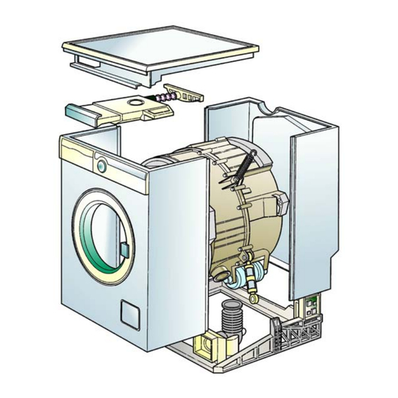
6 STRUCTURAL CHARACTERISTICS 6.1 “NEXUS” technology These appliances are produced using the NEXUS technology, a patented system consisting of five sub- assemblies: Base Cabinet Control panel support Washing group Work-top 1. Base 2. Front cabinet shell 3. Rear cabinet shell 4. -
Page 30: Washing Machine With 32 Cm-Depth Cabinet
6.1.1 Washing machine with 32 cm-depth cabinet 1. Front cabinet shell 2. Tub 3. Drum rotation motor 4. Drain pump 5. Damper 6. Heating element 7. Thermostat 8. Pressure switch 9. Capacitor/suppressor 10. Base 6.2 Base 1. Base 2. Filter body 3. -
Page 31: Cabinet
6.4 Cabinet The cabinet consists of two half-shells in enamelled sheet metal, which are secured to a Carboran base. The support cross-member (in galvanized sheet metal) is screwed to the upper section of the cabinet. The work-top is screwed to the rear section of the cabinet shell. - Page 32 P63 square P62 (P65) soft P62 INPUT NEAT(JETSY- IZ) P63 soft - large door SOI/DT 2002-05 eb 599 35 23-17...
-
Page 33: Porthole Door
6.5 Porthole door Several types of porthole door may be fitted: • standard (26 cm) or large (30 cm) • angle of aperture (130° or 180°) • alignment with front panel (flush or protruding) • differently-styled surrounds • type of aperture (various handles, or button on control panel) 6.5.1 Examples of porthole doors 1. -
Page 34: Porthole Door With Button-Actioned Aperture
6.5.2 Porthole door with button-actioned aperture On certain models, the door can be opened by pressing a button on the control panel. All models with the P66 (32 cm) cabinet are fitted with this feature. 1. Door aperture button 2. Spring 3. -
Page 35: Control Panel
6.6 Control panel The plastic control panel is secured to the control panel support by anchor tabs and one or more screws. The shape of the control panel depends on the styling and therefore the brand of the appliance. Various types of control panels are available for each styling, each fitted with a different number of buttons and knobs. -
Page 36: Washing Groups
6.7 Washing groups The washing group is suspended from the support cross-member by two helical springs. The oscillation of the washing group is absorbed by the two dampers attached to the base. Balancing of the washing group is provided by a front counterweight in cement and by a rear counterweight. Some models are not fitted with the rear counterweight. -
Page 37: Types Of Washing Groups
6.7.2 Types of washing groups Appliances in the NEXUS range may be fitted with washing groups of varying dimensions and spin speeds. CARBORAN Load capacity (cotton) Type Drum volume Rated Max. 3 Kg 3,5 Kg 26 l 4 Kg 4,5 Kg 38 l 4,5 Kg 5 Kg... -
Page 38: Washing Group In Carboran
6.7.3 Washing group in Carboran The tub consists of two half-shells in Carboran, secured together by a series of self-tapping screws. The two counterweights are screwed to the half-shells. The bellows seal is secured to the front half-shell by a metal elastic ring. -
Page 39: Stainless Steel Washing Group
6.7.4 Stainless steel washing group 1. Tub casing 9. Ring securing the seal to the tub 2. Band spring 10. Bellows seal 3. Tub support band 11. Ring securing the seal to the cabinet 4. Drum 12. Rear counterweight 5. Flange seal 13. -
Page 40: Drum
6.7.5 Drum The drum consists of a stainless steel casing to which the two flanges are crimped. Three Carboran lifters are pressure-fitted to the internal face of the drum. The drum spider, in aluminium alloy, is secured to the edge of the drum by screws. -
Page 41: Drum Rotation Drive Belt
6.7.6 Drum rotation drive belt These appliances are fitted with elastic drive belts. The motor is mounted in a fixed position, and no regulation is possible. 1. Motor pulley 2. Elastic drive belt 3. Drum pulley Different types of drive belts, produced by various manufacturers and with different characteristics, are used in production: •... -
Page 42: Detergent Dispenser
6.8 Detergent dispenser 6.8.1 Detergent dispenser with distribution levers This type of detergent dispenser is used in models featuring: • electromechanical timers • hybrid timers • MWM electronic control systems, which feature an electromechanical distributor for movement of the levers Two versions of this dispenser exist: one is larger, the other is of reduced size (ecological). - Page 43 "LONG" DISPENSER "SHORT" DISPENSER (ecological) 1. Fill hose 11. Detergent drawer 1. Fill hose 11. Detergent drawer 2. Washer 12. Siphon for additives 2. Washer 12. Siphon for additives 3. Cable clamp 13. Spring 3. Cable clamp 13. Spring 4. Extension hose 14.
-
Page 44: Detergent Dispenser With Multiple-Outlet Solenoid Valve ("Long" Version)
6.8.2 Detergent dispenser with multiple-outlet solenoid valve ("long" version) Various versions of this type of detergent dispenser are used in washers and washer-dryers featuring: • EWM2000 control system • EWM1000 control system The water is ducted into the detergent compartment by a solenoid valve with one inlet and 2 or 3 outlets. Some models are fitted with a second solenoid valve for the introduction of hot water. - Page 45 6.8.2.1 Principles of operation Water fill to pre-wash compartment (Pre-wash solenoid valve) • This version is used in models with three compartments (EWM1000) and 3 or 4 compartments (EWM2000). The detergent contained in compartment "a" is introduced at the beginning of the pre-wash phase.
-
Page 46: Detergent Dispenser With Multiple-Outlet Solenoid Valve ("Short" Version)
6.8.3 Detergent dispenser with multiple-outlet solenoid valve ("short" version) Various versions of this type of detergent dispenser are used in washers featuring: • EWM2000 control system • EWM1000 control system 1. Fill hose 2. Washer 3. Cable clamp 4. Solenoid valve support 5. - Page 47 6.8.3.1 Operating principle Water fill to pre-wash compartment (Pre-wash solenoid valve) • This version is used in EWM2000/1000 models with 3- compartment detergent dispensers. The detergent contained in compartment "a" is introduced at the beginning of the pre- wash phase. •...
-
Page 48: Drain/Circulation Circuits
6.9 Drain/circulation circuits The drain circuit differs according to the structure of the model and the washing system used. 6.9.1 Washers with traditional washing systems 1. Tub 2. Tube between tub and filter body 3. Filter body 4. Drain pump 5. -
Page 49: Washers With Traditional Washing System And "Eco-Ball" Ball Valve
6.9.2 Washers with traditional washing system and “ECO-BALL” ball valve 1. Drain pump 2. Pump cover 3. Filter body 4. Drain filter 5. Washer 6. Filter knob 7. Tube between tub and filter body 8. Ball 9. Pressure chamber 6.9.2.1 Drain filter This drain system is self-cleaning: the filter traps only objects of a certain size. -
Page 50: Washers With Traditional Washing System And "P66" (32 Cm) Cabinet
6.9.3 Washers with traditional washing system and “P66" (32 cm) cabinet 1. Tub 2. Pressure chamber 3. Tube between tub and pump 4. Drain pump 5. Drain hose In these appliances, the drain circuit is self-cleaning: the siphon on the tube between the tub and the pump traps objects (coins, hair clips etc.) that might jam the pump. -
Page 51: Jetsystem Washing Machines (With Circulation Pump)
6.9.4 Jetsystem washing machines (with circulation pump) 1. Filter body 2. Circulation pump 3. Circulation tube 4. Drain pump 1. Tube between tub and filter body 2. Pressure chamber 3. Filter body 4. Washer 5. Cap 6. Drain filter 7. Washer (OR) 8. -
Page 52: New Jet" Circulation Circuit (Circulation Pump) - Version P63Bd
6.9.5 “NEW JET” circulation circuit (Circulation pump) – version P63BD 1. Tube between tub and filter body 2. Filter body 3. Drain filter 4. Washer 5. Filter knob 6. Drain pump 7. Pump cover 8. Circulation pump intake tube 9. Circulation pump 10. -
Page 53: Jetsystem Washing Machines (Circulation Pump) With Heat Exchanger
6.9.6 Jetsystem washing machines (Circulation pump) with Heat exchanger (featured on a few older models only) 1. Filter body 2. Heat exchanger (Heating element) 3. Safety thermostat 4. Thermostats 5. Circulation pump 6. Circulation tube 7. Return tube 8. Drain pump 1. -
Page 54: Jetsystem Washing Machines With Neat Cabinet (Jetsy- Iz)
6.9.7 Jetsystem washing machines with NEAT cabinet (JETSY- IZ) 1. Drain pump 2. Filter 3. Filter body 4. Circulation pump 1. Tube between tub and filter body 2. Pressure chamber 3. Filter body 4. Washer 5. Cap 6. Drain filter 7. -
Page 55: Washer-Dryer Components
7 WASHER-DRYER COMPONENTS 1. Tub 2. Drying condenser 3. Fan 4. Drying heater casing 5. Cold water fill solenoid 6. Drain pump 7.1 Fan assembly The fan ducts the air from the condenser to the casing containing the heating elements. The fan is actioned by a drive belt attached to the fan motor. -
Page 56: Heater Element Casing
7.2 Heater element casing The heating element casing consists of two half- shells in aluminium alloy. The shells are joined together by screws and sealed with silicone. The casing is insulated by two half-shells in basalt rock wool encased in a sheet of aluminium and secured by two straps. -
Page 57: Drying Condenser
7.3 Drying condenser The drying condenser consists of a plastic structure which is connected to the lower section of the tub by a rubber sleeve, and to the fan by a seal. The condenser is attached to the base of the appliance. The humid air enters from the lower section of the condenser, while a jet of cold water is introduced from the upper section. -
Page 58: Determining The Drying Time
7.3.1 Determining the drying time (models with electronic control system only) In certain models with electronic control (EWM2000/MWM), the user can select automatic drying cycles. In this case, the drying time is determined according to the desired degree of humidity. The electronic control system utilizes an NTC sensor, fitted to the drying condenser, to calculate the drying time. -
Page 59: Condensation Water Fill
7.3.2 Condensation water fill 1. Solenoid valve 2. Tube from Solenoid valve to Coupling 3. Coupling 4. Tube from Coupling to condenser 5. Siphon on Tube from detergent dispenser to tub The condensation water is delivered by a section of the cold water solenoid valve, whose delivery is 0.4 litres per minute. -
Page 60: Electrical Components
8 ELECTRICAL COMPONENTS 8.1 Control systems The operation of the appliance depends on the type of control system used, since the control system governs the various operations comprising the washing cycle. Types of control systems • Electromechanical timers (F50-F51-F52-F53): the controls are actuated by the commutator contacts, which are actioned by a series of cammes. -
Page 61: Suppressor
8.2 Suppressor 8.2.1 General characteristics The suppressor is connected to the input of the appliances power line, and prevents radiofrequency disturbance from entering the power circuit. 8.2.2 Electrical symbols 8.2.3 Circuit diagrams 8.2.4 Checking for efficiency THE APPLIANCE GENERATES RADIOFREQUENCY DISTURBANCE: check the efficiency of the earth circuit THE APPLIANCE IS INOPERATIVE: Use an ohmmeter to check that the component is not faulty:... -
Page 62: Push-Button
8.3 Push-button 8.3.1 General characteristics Single-button versions are used. These differ as regards the number and functionality of the contacts: switch deviator (single- or two-pole) 8.3.2 Electrical symbol Normally-closed switch Normally-open switch Deviator 8.3.3 Checking for efficiency DOES NOT POWER THE APPLIANCE OR DOES NOT PERFORM THE SPECIFIC FUNCTION: Use a tester to check for correct closure (or aperture) of the various contacts. -
Page 63: Door Safety Interlock (Traditional Version)
8.4 Door safety interlock (traditional version) 8.4.1 General characteristics The electromechanical door safety device performs the following functions: • When powered, the voltmetric safety interlock closes the contacts of the main switch that powers the electrical components of the appliance (only if the door is closed). -
Page 64: Electrical Symbol
8.4.2 Electrical symbol Common contact PTC power supply contact Main switch contact 8.4.3 Circuit diagrams Connector 8.4.4 Version with pneumatic device (certain models only) 1. Air intake aperture 2. Membrane 3. Latch 4. Spring 5. Lever A tube connects the door delay device to the filter body. When the pressure on the membrane is greater than the force exerted by the counterspring (100 ±... -
Page 65: Instantaneous Door Safety Interlock
8.5 Instantaneous door safety interlock 8.5.1 General characteristics Certain models with electronic control systems feature an instantaneous door safety interlock. In this case, the door can be opened as soon as the drum comes to a stop. 8.5.2 Operating principle 1. -
Page 66: Electrical Symbol
8.5.2.3 Protective cut-out for solenoid valve A PTC, connected in series to the solenoid valve, serves as a current limiter (i.e. overheating cut-out) in the following cases: → If the triac on the main PCB is short-circuited → If the START/PAUSE button is pressed repeatedly (more than 10 times) 8.5.3 Electrical symbol 8.5.4... -
Page 67: Solenoid Valve
8.6 Solenoid valve 8.6.1 General characteristics The solenoid valve ducts water through the detergent dispenser, and is controlled electrically by the pressure switch. 1. Water intake 2. Solenoid valve body 3. Filter 4. Flow reducer 5. Coil 6. Spring 7. Moving core 8. -
Page 68: Electrical Symbol
8.6.2 Electrical symbol 8.6.3 Checking for efficiency WATER FILL CONTINUES WHEN THE APPLIANCE IS SWITCHED OFF: Solenoid valve jammed mechanically. Replace the solenoid valve WATER FILL CONTINUES DURING THE WASHING CYCLE: Check the hydraulic circuit of the pressure switch and the pressure switch itself. NO WATER FILL: 1. -
Page 69: Pressure Switch
8.7 Pressure switch 8.7.1 General characteristics The function of the pressure switch is to determine the quantity of water to be introduced into the tub. In other words: It controls the water fill levels during the washing phases. It acts as an anti-boiling safety device when connected in series to the heating element. -
Page 70: Operating Principle
8.7.3 Operating principle Tub empty Water flows into the tub Water is drained from the tub As there is no water in the tub, When the connection between the As the level of water in the tub there is no pressure on the tub and the pressure chamber is diminishes, the pressure exerted diaphragm, which thus remains in... -
Page 71: Analogue (Electronic) Pressure Switch
8.8 Analogue (electronic) pressure switch 8.8.1 General characteristics The electronic pressure switch is an analogue device whose function is to control the level of water in the tub; it is used in certain models with electronic control systems (EWM2000 - MWM1.5). The electronic circuit is connected directly to the main PCB. -
Page 72: Electrical Symbol
8.8.3 Electrical symbol 8.8.4 Circuit diagrams and operating frequency Version for MWM1.5 control systems Version for EWM2000 control systems 8.8.5 Checking for efficiency In the event of a fault in the pressure switch, the operation of the appliance is immediately interrupted. Where possible, always read the alarm code. -
Page 73: Water Distributor
8.9 Water distributor 8.9.1 General characteristics The water distributor is used in models with MWM electronic control systems, and performs the following functions: It actions the levers in the detergent dispenser in order to duct water through the various compartments during the course of the washing cycle. -
Page 74: Electrical Symbol
A = Pre-wash B = Wash C = Bleach D = Conditioner Contact base Position of lever 8.9.3 Electrical symbol 8.9.4 Contact closure diagram SOI/DT 2002-05 eb 599 35 23-17... -
Page 75: Induction (Asynchronous) Motors
8.10 Induction (asynchronous) motors 8.10.1 General characteristics The function of the motor is to rotate the drum at different speeds: high speed for the spin phases low speed for the wash phases The primary characteristics of these motors is that they do not require a start-up current. -
Page 76: Reversal Of Direction Of Rotation During Washing
8.10.2 Reversal of direction of rotation during washing The windings are designed to provide rotation in both directions, depending on the way in which the capacitor is connected. Each functions alternately as a primary winding and start-up winding. When reverse rotation is required, the switching contact of the timer reverses the connection of the capacitor between the two windings, thus reversing the direction of rotation. -
Page 77: Motor With Speed Variator
8.10.5 Motor with speed variator On certain models, spin speeds from 600 to 800 rpm can be obtained using a motor fitted with a speed variator (the speed during the washing phase is always 55 rpm). 1. Motor 2. Speed variator Low speed High speed The motor pulley consists of two disks: the first is attached to the... -
Page 78: Commutator Motor
8.11 Commutator motor 8.11.1 General characteristics Commutator motors are fitted to appliances with spin speeds of between 600 and 1,600 rpm. These motors are manufactured by: • SOLE (formerly ZEM) • FHP (formerly AEG) • CESET It is possible that motors produced by manufacturers other than the original manufacturer may have the same part number, but these are perfectly interchangeable. - Page 79 8.11.2.1 Control of the speed of the motor Speed control is obtained by using an electronic control system to vary the voltage (V) applied to the motor. The technique used consists of a "phase division" performed by the Triac. A Triac is a bi-directional electronic switch.
-
Page 80: Electrical Symbols
8.11.2.3 Tachymetric generator As in all motors powered in series, the speed of the commutator motor depends on the load. In other words, its speed diminishes as the load increases This makes it necessary to ensure that the power voltage to the motor, and therefore its speed, be constantly controlled by an electronic speed control system. -
Page 81: Circuit Diagram
8.11.4 Circuit diagram P = Motor overload cut-out R = Rotor S = Stator T = Tachymetric generator 8.11.5 Checking for efficiency 1. Check the connector blocks (wiring) and check for any bent or detached terminals. 2. Check for traces / residue / deposits of water or detergent and identify their source. 3. -
Page 82: Ac/Dc Converter
8.12 AC/DC converter 8.12.1 General characteristics This component is fitted only to certain models with electronic control, and serves to convert the alternating current generated by the triac on the main PCB into direct current used to power the drum rotation motor. 8.12.2 Electrical symbol 8.12.3 Circuit diagram 1.2 mH... -
Page 83: Heating Element
8.13 Heating element 8.13.1 General characteristics The heating element that heats the washing water is encapsulated, i.e. inserted into a watertight stainless steel tubular casing. Typical power ratings: 1500W 1950W 2500W 3000W (some models may be fitted with heating elements with different power ratings) 1. -
Page 84: Electrical Symbol
8.13.1.2 Seal The seal between the tub and the heating element is provided by a seal which expands against the nut. 1. Fixed flange 2. Washer 3. Moving flange 4. Nut 5. Heating element terminals 8.13.2 Electrical symbol 8.13.3 Checking for efficiency DOES NOT HEAT: check that the heating element is not broken: measure the resistance across the two terminals. -
Page 85: Heat Exchanger
8.14 Heat exchanger 8.14.1 General characteristics 1. External casing 2. Heat exchanger 3. Heating element 4. Thermostat In certain Jetsystem models, the water is heated by a heat exchanger (not recent models). The heat exchanger consists of a cylindrical body in aluminium alloy, lined with a layer of "teflon" to prevent the formation of scale. -
Page 86: Drying Heater (Washer-Dryers)
8.15 Drying heater (washer-dryers) 8.15.1 General characteristics The armoured drying heater is inserted into a watertight stainless steel tubular casing, and consists of two branches: when drying cotton fabrics, both heating elements are switched on (full power). when drying synthetic fabrics, only one element is switched on (half-power) to ensure delicate drying. Typical electrical power ratings (depending on the model): 1000+1000W... -
Page 87: Bi-Metal Thermostats
8.16 Bi-metal thermostats 8.16.1 General characteristics This type of thermostat, which exists in various versions with one or two contacts (normally closed or normally open) is utilized for a number of applications: control of the temperature of the washing water control of the temperature of the drying air as a safety device for overheating during washing and/or drying. -
Page 88: Adjustable Thermostat
8.17 Adjustable thermostat 8.17.1 General characteristics Thermostats are used to control and regulate the temperature of the washing water. Some thermostats are based on the fluid expansion effect, and their intervention temperatures can be adjusted. 1. Bulb 2. Capillary 3. Capillary sheath 4. -
Page 89: Ntc Temperature Sensor
8.18 NTC temperature sensor 8.18.1 General characteristics In certain models (i.e. those with hybrid or electronic timers), an NTC sensor is used to control the washing temperature. In these sensors, the internal resistance decreases as the temperature increases. This reduction in resistance is detected by the electronic control system which, when the desired temperature is reached, disconnects the heating element. -
Page 90: Drain Pump
8.19 Drain pump 8.19.1 General characteristics The function of the drain pump is to discharge the water at the end of each phase of the washing cycle. These centrifugal pumps are actioned by a synchronous motor. 1. Impeller 2. Rotor 3. -
Page 91: Circulation Pump
8.20 Circulation pump 8.20.1 General characteristics Jetsystem models are fitted with a synchronous circulation pump which continuously circulates the water from the filter body into the tub through the bellows seal. In certain models (those fitted with a heat exchanger, but not more recent models) the temperature control thermostats may be fitted to the circulation pump. -
Page 92: Drying Timer (Washer-Dryers)
8.21 Drying timer (washer-dryers) 8.21.1 General characteristics The timer is a timing device that powers the components needed for the drying cycle; it is used in models with electromechanical and hybrid timers. Actuation is by the contacts, which are actioned by a series of cammes. -
Page 93: Fan Motor (Washer-Dryers)
8.22 Fan motor (washer-dryers) 8.22.1 General characteristics The motor which actions the air circulation fan for the drying phase is of the single-phase asynchronous type. The rotor is of the "squirrel cage" type. The velocity of the shaft is approximately 2,800 rpm at a voltage of 220-240V/50Hz. -
Page 94: Circuit Diagrams
8.23 Circuit diagrams Each model produced is accompanied by a wiring diagram and a basic circuit diagram. 8.23.1 Wiring diagram An example of a wiring diagram is shown below. The wiring diagram may be used to check for correct connection of the wiring connectors to the various electrical components. SOI/DT 2002-05 eb 599 35 23-17... - Page 95 8.23.1.1 Wiring Two types of wiring harness are used for the various models: • Modular: the wiring harness consists of a series of sections fitted with connectors. • Single: the wiring consists of a single main harness. There may be separate wires for connection to earth.
-
Page 96: Basic Circuit Diagram
8.23.2 Basic circuit diagram An example of a basic circuit diagram is shown below. The circuit diagram should be used to check the appliance for correct operation in the diagnostics phase (in conjunction with the timer diagram, if present). Wire Timer connector Internal connection to Timer motor... -
Page 97: Access To Components
9 ACCESS TO COMPONENTS 9.1 Work-top a. Remove the two rear screws (1), push the work-top towards the rear of the appliance and detach. 9.1.1 Pressure switch a. Remove the work-top b. Detach the wiring connectors c. Press the anchor tabs (2) and pull towards the rear d. -
Page 98: Control Panel (Standard Version)
9.2 Control panel (standard version) 9.2.1 Control panel – versions for “soft” cabinet a. Remove the work-top b. Extract the detergent drawer (8) c. Remove the screws that secure the control panel to the control panel support (9) d. For models with knobs external to the control panel: release the knob cover by pressing the hole gently with a small screwdriver and turning the knob cover counter-clockwise (10) e. -
Page 99: Timer
9.2.3 Timer Version with internal knobs on control panel: a. Remove the work-top. b. Remove the control panel c. If present, remove the screw that secures the knob-spindle (or coupling) and remove the knob. d. Remove the two screws which secure the timer to the cross-member (18). -
Page 100: Electronic Control Systems
9.3 Electronic control systems 9.3.1 Main PCB (MWM-EWM2000) a. Remove the top. b. Remove the screws which secure the support to the board casing (23-24) c. Detach the wiring from the supports d. Extract the casing-PCB assembly e. Detach the connectors 9.3.2 Control/display board The way in which these boards are fastened depends on the styling version and the type of electronic... -
Page 101: Access From The Porthole Door
9.4 Access from the porthole door 9.4.1 Porthole door a. Remove the two screws which secure the door to the hinge (30) b. Remove the screws which secure the surround-flange (if present) and detach the flange from the surround. c. Remove the glass door panel. d. -
Page 102: Rear Cabinet Shell
9.5 Rear cabinet shell a. Remove the top b. Remove the screws which secure the cabinet shell to the upper cross-member (34) c. Remove the screw head masking caps and remove the lateral screws which secure the cabinet shell to the base (35) d. -
Page 103: Thermostat/Ntc Sensor
9.5.3 Thermostat/NTC sensor a. Remove the rear cabinet shell. b. Detach the drive belt from the pulleys (if necessary). c. Detach the wiring connectors (fixed-temperature thermostats and NTC sensors) d. Remove the thermostat/sensor from the sealing ring (41). Refer to section 9.2.7 for removal of the adjustable thermostat (42). -
Page 104: Detergent Dispenser
9.5.5 Detergent dispenser a. Remove the rear cabinet shell. b. Unscrew the clamp and detach the tube from the detergent dispenser to the tub c. Detach the steam venting tube from the tub (if present) d. Extract the detergent drawer (8) e. -
Page 105: Adjusting The Dispenser Levers
9.5.8 Adjusting the dispenser levers a. Turn the timer knob to the start of a programme in which water is ducted through the washing compartment b. Check that the "1" is aligned with "b" on the dispenser. If not, lift pointer "2" and rotate the eccentric camme "3"... -
Page 106: Washing Group (Carboran-Inox)
9.6 Washing group (Carboran-inox) a. Remove the fixing ring and detach the bellows seal from the front panel b. Remove the rear shell c. Remove the clamps from the tub suspension springs (53) d. Detach the various hoses from the tub (dispenser-tub, steam venting hose, tub-manifold etc.) e. -
Page 107: Front Counterweight (Carboran Tub)
9.7.3 Front counterweight (Carboran tub) ⇒ version with front-mounted fixing screws a. Remove the tub b. Replace both the shell and the front counterweight to prevent the possibility of breakage due to vibrations ⇒ version with fixing screws on the perimeter of the tub a. -
Page 108: Tub Support Band
9.8.3 Tub support band a. Remove the tub from the appliance b. Release the retaining spring using a length of steel wire c. Remove the two nuts which secure the band to the tub (near the motor) d. Remove the support band Re-assembly: First fit the two bolts which secure the band to the tub, then, using a length of steel wire, re-attach the retaining spring 9.8.4... -
Page 109: Drum Lifter
9.9 Drum lifter The drum lifter can be removed from the interior for stainless steel tubs (G10-G11-G12-G13) and the type G17-G18-G19 Carboran tubs. For type G20-G21 Carboran tubs, it is necessary to remove the drum before replacing the lifter. Removal a. -
Page 110: Access To The Pumps/Manifolds
9.10 Access to the pumps/manifolds Important! Do not fit the circulation pump in place of the drain pump and vice versa. 9.10.1 Drain pump (standard version) To access the drain pump, it is not necessary to remove the rear cabinet shell. The pump can be accessed from the base. a. -
Page 111: Drain Pump - Models With Neat Cabinet (Jetsy- Iz)
9.10.4 Drain pump - models with Neat cabinet (Jetsy- IZ) a. Lay the appliance face-down, remove the screws which secure the filter body and remove the filter from the base (70) b. Detach the drain hose from the pump. c. Press down the two anchor tabs and detach the pump from the filter body (71). d. -
Page 112: Drain Filter Body (Standard Version)
9.10.9 Drain filter body (standard version) a. Remove the rear cabinet shell b. Lay the appliance face-down c. Remove the circulation pump (if present) d. Detach the hoses from the filter body e. Remove the screws which secure the front shell to the base (75) Raise the base in order to detach the filter body from the front shell g. -
Page 113: Front Cabinet Shell
9.11 Front cabinet shell a. Remove the top b. Remove the control panel c. Remove the porthole door d. Detach the bellows seal from the front panel e. Remove the two screws which secure the door delay device to the front panel Remove the rear shell g. -
Page 114: Access To Specific Washer-Dryer Components
9.12 Access to specific washer-dryer components 9.12.1 Bellows seal and drying duct a. Remove the work-top b. Remove the screw which secures the duct to the tank (80) c. Open the porthole door, remove the screw which secures the duct to the cabinet, detach the duct from the heating element casing and pull the seal downwards (81) d. -
Page 115: Rear Cabinet Shell
9.12.2 Rear cabinet shell a. Remove the top b. Remove the screws which secure the shell to the base and to the control panel support c. Remove the screw which secures the fan to the shell (86) 9.12.3 Motor-Fan assembly a. -
Page 116: Drying Heater Casing
9.12.5 Drying heater casing a. Remove the rear cabinet shell b. Detach the connectors from the heating elements and from the thermostats c. Detach the fan from the casing (9.12.3) d. Remove the screws which secure the casing to the duct and the two screws which secure it to the cross-member e. -
Page 117: Tools And Materials
10 TOOLS AND MATERIALS 10.1 Standard tools 1. Set of standard flat-head screwdrivers (small, medium, large) 2. Set of cross-head ("Phillips") screwdrivers 3. Set of socket screws (7, 8, 10, 13, 15, 17mm) 4. Insulated scissors. 5. Allen keys (5-6 mm) 6. -
Page 118: Materials
14. Hammer (300 g approx.) 15. Plastic or rubber-head hammer 16. Two narrow-tipped chisels (mm 200x8) 17. Steel wire 18. "L"-shaped lever (used to detach the support band from stainless steel tubs) When replacing the bearings, use spacers of the appropriate diameter 10.2 Materials soap and water...
Need help?
Do you have a question about the P6000 (Nexus) Series and is the answer not in the manual?
Questions and answers