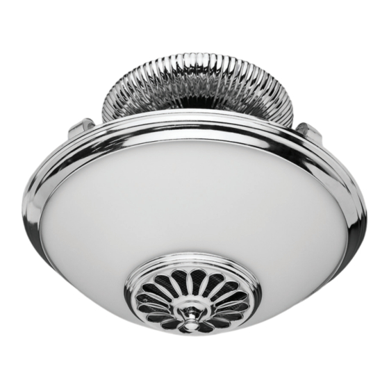
Hunter Illumi-Heat Owners And Installation Manual
Light and heat on demand
Hide thumbs
Also See for Illumi-Heat:
- Installation instructions manual (13 pages) ,
- Owner's manual (8 pages)
Summary of Contents for Hunter Illumi-Heat
- Page 1 Illumi-Heat™ Illumi-Heat™ Illumi-Heat™ Light & Heat on Demand™ Light & Heat on Demand™ Light & Heat on Demand™ Owner’s Guide and Installation Manual Manual De Propietario Form# 43566-01 20100625 ©2010 Hunter Fan Co.
- Page 2 FOLLOWING: • Be cautious! Read all instructions and safety information before installing your new Illumi-heat semi-flush fixture. Carefully review the assembly illustrations. • Use this unit only in the manner intended. • All wiring must be in accordance with national and local electrical codes. If you are unfamil- iar with wiring, you should use a qualified electrician.
- Page 3 Parts Verify all parts were in the box before installing. Wires: Hanger Bracket Black, White, Copper (Ground) Threaded Rod Canopy Top Finial Receiver Transmitter and Light Sockets (3) Transmitter Holder Heater/Light Fixture (not to scale) Glass Dome Wire Connectors (3) (not to scale) Bottom Finial Tools Needed (not supplied)
- Page 4 Pre-Installation for Multiple Illumi-Heat Units in Your Home If you are going to install more than one Illumi-Heat in your home, then you will need to assign each unit a its own unique Transmitter / Receiver Code. 1) Looking at the fixture from its top, locate the Receiver, as shown in Figure 1.
- Page 5 Pre-Installation for Multiple Illumi-Heat Units in Your Home (Continued) 3) Configure the Receiver Switches to your desired code. Make a note of which Receiver Switches you turned On and turned Off. NOTE: Make certain each Receiver is assigned a different code.
-
Page 6: Installation
Installation 1) If you are replacing an existing light fixture, disconnect and remove the old fixture and hanger bracket, leaving the exposed wires coming from the electrical box. 2) Attach the Hanger Bracket assembly to the electrical box as shown in Figure 5. Electrical Box Hanger Bracket Figure 5 - Attach Hanger to Electrical Box... - Page 7 Installation (Continued) 3) Suspend the fixture by placing the Cable Loop over the Cable Loop Hanger. See Figure 6. Cable Loop Hanger Cable Loop Figure 6 - Suspend the Fixture 4) Use UL-approved wire connectors to connect the wires, black-to-black, white-to-white. Loop the ground wires around the Ground Screw, then tighten the Ground Screw.
- Page 8 I N S TA L L AT I O N c o n t i n u e d Installation (Continued) 5) Swing the Fixture up so that the threaded rod exits the hole in the bottom of the canopy. See Figure 8.
- Page 9 I N S TA L L AT I O N c o n t i n u e d Installation (Continued) 6) Position the top finial over the threaded rod, and tighten the top finial until tight. See Figure 9. Threaded Rod Top Finial Figure 9 - Top Finial Nut Installation...
- Page 10 I N S TA L L AT I O N c o n t i n u e d Installation (Continued) 8) Position the Glass Dome under the Heater/Light Fixture as shown in Figure 11a. Then, place the Glass Dome over the Heater/Light Fixture as shown in Figure 11b. Heater Glass Dome Install Glass Dome...
-
Page 11: Operation
Light On Figure 13 - Transmitter Buttons 4) Mount the Transmitter Holder over the Illumi-Heat’s wall switch using the the existing wall plate screws. See Figure 14. 5) The Transmitter can be placed in the Transmitter Holder for convenience or safekeeping. -
Page 12: Troubleshooting
Troubleshooting Problem: No functions operate 1. Replace fuse. Turn ON circuit breaker. Turn ON wall switch. 2. Verifiy wiring connections. 3. Set transmitter and receiver to same dip switch setting. 4. Replace with new, 12 Volt alkaline battery. Problem: Operates only at close range. 1.


Need help?
Do you have a question about the Illumi-Heat and is the answer not in the manual?
Questions and answers