Table of Contents
Advertisement
Advertisement
Table of Contents

Related Manuals for Hunter Set & Save 47350A


Summary of Contents for Hunter Set & Save 47350A
-
Page 1: Programmable Thermostat
41659_model_web.pmd ® Programmable Thermostat Owner’s Manual Model 47350A... -
Page 2: Table Of Contents
Read This Before Installing Thermostat Features What You Need Remove Old Thermostat Wire Labeling Mount Wallplate and Thermostat Connect Wires and Mount Thermostat Cover to Wall Plate Selector Switches Setting Time and Day Default Programs Personal Program Schedule Manual Programming... -
Page 3: Table Of Contents
This Hunter Thermostat will NOT control multi- stage heat pumps or 110/220 Volt systems. COMPRESSOR PROTECTION The thermostat provides a 3.5 minute delay after shutting off the heating or cooling system before it can be restarted. This feature will prevent damage to your compressor caused by rapid cycling. -
Page 4: Power Failure
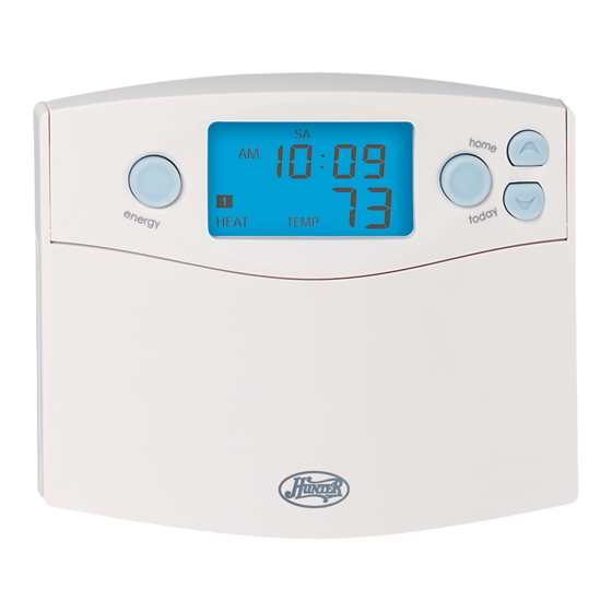
When this message occurs, install 2 new AA batteries. You have approximately 1 minute to ENERGY STAR ® As an ENERGY STAR ® Partner, Hunter Fan Co. has determined that this programmable thermostat meets the ENERGY STAR ® guidelines for energy efficiency. Features LCD Display: Shows time, day, temperature, program number, and other feature information as required. -
Page 5: Installation What You Need
41659_model47350A_web.pmd INSTALLATION What You Need This thermostat includes two #8 screws and two wall anchors for mounting. To install your thermostat, you should have the following tools and materials. Remove Old Thermostat CAUTION: Do not remove any wiring from exist- ing thermostat before reading the instructions carefully. -
Page 6: Mount Wallplate And Thermostat
Figure 2 NOTE: 5-wire Systems If your thermostat has one wire marked R or RH (4-wire system), then leave the jumper wire between the RH and RC terminals on the wallplate. Otherwise, if you have separate RH and RC wires (5-wire system), then remove the jumper wire between the RH and RC terminals. -
Page 7: Connect Wires And Mount Thermostat Cover To Wall Plate
Insert the bottom tab on the thermostat body into the slot at the bottom of the wallplate. Press the top of the thermostat body to snap it into the wallplate. Refer to Figure 6. (NOTE: Do not force Selector Switches... -
Page 8: Setting Time And Day
During time and day setting mode, the temperature and program displays will go blank. Example: Set the Thermostat to the current time of 2:16 pm on Saturday. Refer to the Steps below. Press to enter time and day setting mode. The cur- rent hour and the AM / PM indicator will be flashing. -
Page 9: Default Programs
8-hour periods during winter can reduce your fuel bill by as much as 33%. By setting your thermostat up The thermostat is pre-programmed for all 7 days of the week as shown below. Program Number Refer to Manual Programming on page 18 for instructions on entering or changing the programs. -
Page 10: Manual Programming
41659_model47350A_web.pmd PROGRAMMING Manual Programming Your thermostat can be programmed for week- days and weekends, or have unique programs for all 7 days. Use Weekday/Weekend Programming below or 7-day Programming on page 21 to enter or revise programs to match your Personal Pro- gram Schedule. -
Page 11: 7-Day Programming
Continue repeating Steps 2 and 3 to program all 7 days of the week. When finished press to return to normal mode. After 15 seconds, the thermostat will return to normal mode automatically. Change the System Selector Switch to the other system, and repeat Steps 1 through 4 above. -
Page 12: Reviewing Programs
/return NOTE: Programs take affect as soon as the thermostat returns to normal mode. If you are armchair programming the thermostat, slide the system selector to the OFF position before mounting the thermostat to the wallplate. Reviewing the Current Temperature Setting Press to display M –... -
Page 13: Operation
41659_model47350A_web.pmd OPERATION System Selector Switch The System Selector switch on the front of the thermostat determines the operating mode of the thermostat. You may select COOL, OFF, HEAT. NOTE: Anytime you install or remove the thermostat from the wallplate, slide the System Selector to the OFF position to prevent the possibility of a rapid system On-Off. -
Page 14: Permanent Manual Override
Vacation Override (Programmable Hold) This thermostat can hold a fixed temperature for a selected number of days (up to 30). After the selected number of days, the thermostat will return to normal program operation. This feature allows you to return home to your normal comfort setpoint temperatures. -
Page 15: Home Today
Press to exit Home Today mode before the schedule ending time. “HOME TODAY” is no longer displayed on the LCD screen, and the thermostat returns to the current program. -
Page 16: Energy Monitor
ALL Energy Monitor counters as well. Filter Monitor Your thermostat also keeps a record of the number of hours your filter has been in use. To maximize your system’s performance and energy efficiency, change or clean your filter regularly. -
Page 17: Auto Recovery
Auto Recovery works in both Heat and Cool modes. When the thermostat is in Auto Recovery mode, the display will alternate RECO with time, and the program indicator will flash. Details of Auto Recovery Operation:... -
Page 18: Span Setting Mode
41659_model47350A_web.pmd OPERATION SPAN Setting Mode Your thermostat is set at the factory to cycle at 0.5˚C (1˚F) above and below the set temperature. (Span = 2) This setting has been designed to pro- vide a comfortable room temperature under most The Span settings remain the same for both HEAT and COOL. -
Page 19: Low Battery Warning
Off. Your system will remain shut-off until the batteries are replaced. NOTE: The thermostat will still keep the current time and your programs in memory until new batteries are installed. After confirming that new batteries have been inserted, the thermostat will return to normal operation. -
Page 20: Troubleshooting
1. Replace Batteries. 1. Check that the time is set properly to “AM” or “PM”. 2. Check that the thermostat is not in “HOLD” or “Home Today” modes. 3. Check for the correct day setting. 1. Move HG/HE selector to opposite position 1. -
Page 21: Wiring Diagrams
41659_model47350A_web.pmd WIRING DIAGRAMS 4-wire Heat/Cool System Wallplate Terminals Relay 5-wire Heat/Cool System Wallplate Terminals Relay X - No Connection Single-stage Heat Pump Wallplate Terminals Relay 2-wire Heat Only Wallplate Terminals X - No Connection Jumper Heat/Cool Cool Heat Relay 24V Supply or Valve Contactor No Jumper... - Page 22 Terminals Relay X - No Connection Ask Your Local Retailer for Other Quality Products from Hunter To locate our nearest Hunter Dealer, call 1-800-4HUNTER, or visit The Hunter Fan Company website: www.hunterfan.com Jumper Selector Heat 24V Heat Relay Supply or Valve...
- Page 23 41659_model47350A_web.pmd Hunter Fan Company Canada 45 BRAMALEA ROAD, SUITE 207 ® BRAMPTON, ONTARIO L6T 2W4 © 2003, Hunter Fan Company Form No. 41659-01, 8/03...
Need help?
Do you have a question about the Set & Save 47350A and is the answer not in the manual?
Questions and answers