Table of Contents
Advertisement
SPLIT-TYPE, HEAT PUMP AIR CONDITIONERS
SERVICE MANUAL
R410A
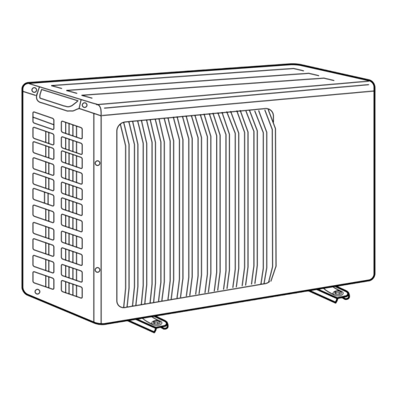
Outdoor unit
[Model name]
PUHZ-SW40VHA
PUHZ-SW50VHA
Salt proof model
PUHZ-SW40VHA-BS
PUHZ-SW50VHA-BS
[Service Ref.]
PUHZ-SW40VHA
PUHZ-SW50VHA
PUHZ-SW40VHA-BS
PUHZ-SW50VHA-BS
Note:
• This manual describes only
service data of the outdoor
units.
CONTENTS
1 REFERENCE MANUAL ·································· 2
2 SAFETY PRECAUTION ·································· 2
3 FEATURES ······················································ 6
4 SPECIFICATIONS ··········································· 6
5 DATA ································································ 8
6 OUTLINES AND DIMENSIONS ······················ 9
7 WIRING DIAGRAM ······································· 10
8 WIRING SPECIFICATIONS ··························· 11
9 REFRIGERANT SYSTEM DIAGRAM ·············· 12
10 TROUBLESHOOTING ··································· 14
11 DISASSEMBLY PROCEDURE ······················ 55
PARTS CATALOG (OCB525)
October 2012
No.OCH525
Advertisement
Table of Contents
Troubleshooting

Related Manuals for Mitsubishi Electric PUHZ-SW40VHA


Summary of Contents for Mitsubishi Electric PUHZ-SW40VHA
-
Page 1: Service Manual
SPLIT-TYPE, HEAT PUMP AIR CONDITIONERS October 2012 No.OCH525 SERVICE MANUAL R410A Outdoor unit Note: [Model name] [Service Ref.] • This manual describes only PUHZ-SW40VHA service data of the outdoor PUHZ-SW40VHA units. PUHZ-SW50VHA PUHZ-SW50VHA Salt proof model PUHZ-SW40VHA-BS PUHZ-SW40VHA-BS PUHZ-SW50VHA-BS PUHZ-SW50VHA-BS CONTENTS 1 REFERENCE MANUAL ··································... -
Page 2: Reference Manual
REFERENCE MANUAL INDOOR UNIT SERVICE MANUAL Model name Service ref. Service manual No. EHST20C-VM6HB EHST20C-VM6HB.UK EHST20C-YM9HB EHST20C-YM9HB.UK EHST20C-VM6B EHST20C-VM6B.UK EHST20C-YM9B EHST20C-YM9B.UK EHST20C-VM6EB EHST20C-VM6EB.UK EHST20C-YM9EB EHST20C-YM9EB.UK OCH531 EHST20C-VM6SB EHST20C-VM6SB.UK EHPT20X-VM2HB EHPT20X-VM2HB.UK EHPT20X-VM6HB EHPT20X-VM6HB.UK EHPT20X-YM9HB EHPT20X-YM9HB.UK EHPT20X-VM6B EHPT20X-VM6B.UK EHPT20X-YM9B EHPT20X-YM9B.UK EHSC-VM6B EHSC-VM6B.UK EHSC-YM9B EHSC-YM9B.UK EHSC-VM6EB... - Page 3 Use the following tools specifically designed for Store the piping indoors, and both ends of the use with R410A refrigerant. piping sealed until just before brazing. (Leave elbow joints, etc. in their packaging.) The following tools are necessary to use R410A refrigerant. Tools for R410A If dirt, dust or moisture enters into refrigerant cycle, that can Gauge manifold...
-
Page 4: Precautions When Reusing Existing R22 Refrigerant Pipes
[3] Service tools Use the below service tools as exclusive tools for R410A refrigerant. Tool name Specifications Gauge manifold · Only for R410A · Use the existing fitting specifications . (UNF1/2) · Use high-tension side pressure of 5.3MPa·G or over. Charge hose ·... - Page 5 (2) Cautions for refrigerant piping work New refrigerant R410A is adopted for replacement inverter series. Although the refrigerant piping work for R410A is same as for R22, exclusive tools are necessary so as not to mix with different kind of refrigerant. Furthermore as the working pressure of R410A is 1.6 times higher than that of R22, their sizes of flared sections and flare nuts are different.
-
Page 6: Features
FEATURES PUHZ-SW40VHA PUHZ-SW40VHA-BS PUHZ-SW50VHA PUHZ-SW50VHA-BS CHARGELESS SYSTEM PRE-CHARGED REFRIGERANT IS SUPPLIED FOR PIPING LENGTH AT SHIPMENT Max. 10m (PUHZ-SW40/SW50) The refrigerant circuit with LEV (Linear Expansion Valve) and power receiver always control the optimal refrigerant level regardless of the length (10 m max. and 5 m min.) of piping. The additional refrigerant charging work during installation often causes problems. - Page 7 Cooling (A35/W18) Outside air temperature (Dry-bulb) + 35 °C Outside air temperature (Wet-bulb) + 24 °C Water temperature (inlet/outlet) + 23 °C/+ 18 °C PUHZ-SW40VHA PUHZ-SW50VHA Service Ref. PUHZ-SW40VHA-BS PUHZ-SW50VHA-BS Single, 50Hz, 230V Power supply (phase, cycle, voltage) Max. current Munsell 3Y 7.8/1.1...
-
Page 8: Data.
DATA 5-1. REFILLING REFRIGERANT CHARGE (R410A : kg) Piping length (one way) Initial Service Ref. charged PUHZ-SW40VHA — — PUHZ-SW40VHA-BS PUHZ-SW50VHA — — PUHZ-SW50VHA-BS Additional charge is required for pipes longer than 10 m. 5-2. COMPRESSOR TECHNICAL DATA (at 20°C) PUHZ-SW40VHA(-BS) Service Ref. -
Page 9: Outlines And Dimensions
OUTLINES AND DIMENSIONS PUHZ-SW40VHA PUHZ-SW40VHA-BS Unit : mm PUHZ-SW50VHA PUHZ-SW50VHA-BS Installation bolt pitch 4-10×21 oval hole Rear air intake Side air intake Air discharge Service panel Terminal connections for charge plug Left Power supply wiring Right Indoor/Outdoor wiring Connection for liquid pipe FLARE 6.35(1/4F) -
Page 10: Wiring Diagram
WIRING DIAGRAM PUHZ-SW40VHA PUHZ-SW40VHA-BS PUHZ-SW50VHA PUHZ-SW50VHA-BS SYMBOL NAME SYMBOL NAME SYMBOL NAME Terminal Block <Power Supply, Indoor/Outdoor> P. B. Power Circuit Board Switch <Function Switch, Model Select> Motor for Compressor R, S Connection Terminal <L/N-Phase> Switch <Model Select> Fan Motor U, V, W Connection Terminal <U/V/W-Phase>... -
Page 11: Wiring Specifications
WIRING SPECIFICATIONS 8-1. FIELD ELECTRICAL WIRING (power wiring specifications) Outdoor unit model SW40, 50V ~/N (single), Outdoor unit power supply 50 Hz, 230 V Outdoor unit input capacity Main switch (Breaker) 16 A Outdoor unit power supply 3 × Min. 1.5 Indoor unit-Outdoor unit 3 ×... -
Page 12: Refrigerant System Diagram
Refrigerant flow in heating Symbol Part name Detail COMP Compressor DC inverter twin rotary compressor (Mitsubishi Electric Corporation) H/P SW High pressure switch (63H) For protection (OFF:4.15MPa) REV/V Change the refrigerant circuit (Heating / Cooling) and for Defrosting Reversing (4-way) valve (21S4) - Page 13 9-1. Refrigerant collecting (pump down) Perform the following procedures to collect the refrigerant when moving the indoor unit or the outdoor unit. 1 Supply power (circuit breaker). * When power is supplied, make sure that “CENTRALLY CONTROLLED” is not displayed on the remote controller. If “CEN- TRALLY CONTROLLED”...
-
Page 14: Troubleshooting
TROUBLESHOOTING 10-1. TROUBLESHOOTING <Error code display by self-diagnosis and actions to be taken for service (summary)> Present and past error codes are logged and displayed on the control board of outdoor unit. Actions to be taken for service, which depends on whether or not the trouble is reoccurring at service, are summarized in the table below. Check the contents below before investigating details. -
Page 15: Self-Diagnosis Action Table
10-3. SELF-DIAGNOSIS ACTION TABLE (Note 1) Refer to indoor unit section for code P and code E. <Abnormalities detected when the power is put on> Abnormal points and detection method Judgment and action Error Code Case 1 No voltage is supplied to termi- 1 Check following items. - Page 16 Error Code Abnormal points and detection method Case Judgment and action 1 Check disconnection or looseness or polarity 1 Contact failure or miswiring of Miswiring of indoor/outdoor unit indoor/outdoor unit connecting of indoor/outdoor unit connecting wire of connecting wire wire indoor and outdoor units.
-
Page 17: Abnormalities Detected While Unit Is Operating
<Abnormalities detected while unit is operating> Abnormal points and detection method Judgment and action Error Code Case 1 Short cycle of indoor unit 1~6 Check indoor unit and repair defect. High pressure (High-pressure switch 2 Clogged filter of indoor unit 63H operated) 3 Decreased airflow caused by Abnormal if high-pressure switch 63H... - Page 18 Abnormal points and detection method Case Judgment and action Error Code Open/short of outdoor unit thermistors 1 Disconnection or contact failure 1 Check connection of connector (TH3,TH6/ (TH3, TH6, TH7, and TH8) of connectors TH7) on the outdoor controller circuit board. Abnormal if open or short is detected Outdoor controller circuit Check connection of connector (CN3) on the...
- Page 19 Abnormal point and detection method Case Judgment and action Error Code To find out the details about U9 error, turn ON SW2-1, 2-2, 2-3, 2-4, 2-5 and 2-6 when U9 error occurs. Detailed To find out the detail history (latest) about U9 error, turn ON SW2-1, 2-2 and 2-6. codes Refer to 10-10.
- Page 20 Abnormal points and detection method Case Judgment and action Error Code 1 Defective outdoor fan (fan 1 Check outdoor unit air passage. Over heat protection motor) or short cycle of out- Abnormal if liquid thermistor (TH3) detects door unit during cooling opera- 70: or more during compressor opera- tion tion.
- Page 21 Abnormal points and detection method Case Judgment and action Error Code 1 Check disconnection or looseness of indoor 1 Contact failure at transmission Remote controller transmission error unit or transmission wire of remote controller. (E0)/signal receiving error (E4) wire of remote controller 2 Set one of the remote controllers “main”...
- Page 22 Error Code Abnormal points and detection method Judgment and action Case 1 Contact failure, short circuit or w Check LED display on outdoor controller Indoor/outdoor unit communication error (Signal receiving error) miswiring (converse wiring) of circuit board. (Connect A-Control service tool 1 Abnormal if indoor controller board could indoor/outdoor unit connecting (PAC-SK52ST))
- Page 23 Abnormal points and detection method Judgment and action Error Code Case Freezing/overheating protection is oper- 1 Overcharge of refrigerant 12 Check operating condition of refrigerant ating 2 Defective refrigerant circuit (clogs) circuit. Overheating protection <Heating mode> 3 Malfunction of linear expansion valve Abnormal if condensing temperature of 4 Reduced water flow 3 Check linear expansion valve.
- Page 24 10-4. TROUBLESHOOTING ■ These sounds can be heard when refrigerant and/or water is (are) fl owing A fl owing water sound or occasional hissing sound is heard. in the indoor unit or refrigerant pipe, or when the refrigerant and/or water is (are) chugging.
-
Page 25: Troubleshooting By Inferior Phenomena
10-5. TROUBLESHOOTING BY INFERIOR PHENOMENA Phenomena Factor Countermeasure 1DC12V is not supplied to remote controller. 1 Check LED2 on indoor controller board. 1. Remote controller display does not work. (Power supply display is not indicated on LCD.) (1) When LED2 is lit. 2DC12~15V is supplied to remote controller, however, Check the remote controller wiring for no display is indicated. - Page 26 Phenomena Factor Countermeasure 7. Remote controller display works 1Linear expansion valve fault 1• Discharging temperature and indoor heat normally and the unit performs Opening cannot be adjusted well due to linear expan- exchanger temperature does not rise. heating operation, however, the sion valve fault.
- Page 27 Symptoms: “PLEASE WAIT” is kept being displayed on the remote controller. Inspection method and Diagnosis flow Cause troubleshooting Check the display time of “PLEASE WAIT” after turning on the main power. 6 minutes 2 minutes or more or less How long is “PLEASE WAIT” •...
-
Page 28: Symptoms: Nothing Is Displayed On The Remote Controller
LED display of the indoor controller board Symptoms: Nothing is displayed on the remote controller LED1 : LED2 : LED3 : Inspection method and Diagnosis flow Cause troubleshooting Check the voltage between S1 and S2 on the terminal block (TB4) of the indoor unit which is used to connect the indoor unit and the outdoor unit. - Page 29 LED display of the indoor controller board Symptoms: Nothing is displayed on the remote controller LED1 : LED2 : LED3 : Inspection method and Diagnosis flow Cause troubleshooting Check the voltage between S1 and S2 on the terminal block (TB4) of the indoor unit which is used to connect the indoor unit and the outdoor unit.
- Page 30 LED display of the indoor controller board Symptoms: Nothing is displayed on the remote controller LED1 : LED2 : LED3 : — Inspection method and Diagnosis flow Cause troubleshooting Check the voltage of the terminal block (TB6) of the remote controller. DC 10V to DC 16V? •...
- Page 31 • Before repair Frequent calling from customers Phone Calls From Customers How to Respond Note Unit does The operating display of remote Check if power is supplied to air conditioner. not operate controller does not come on. Nothing appears on the display unless power is at all.
- Page 32 Phone Calls From Customers How to Respond Note The room cannot be cooled or heated sufficiently. Check the set temperature of remote controller. The outdoor unit cannot be operated if the set temperature is not appropriate. The outdoor unit operates in the following modes. COOL: When the set temperature is lower than the room temperature.
- Page 33 Phone Calls From Customers How to Respond Note Something Air blows out for a while after However, this control is also This is not a malfunction. is wrong HEAT operation is stopped. The blower is operating just for cooling down the applied to the models which with the heated-up air conditioner.
- Page 34 The indoor unit does not receive a signal from remote controller at a long distance. 10-6. HOW TO CHECK THE PARTS PUHZ-SW40VHA PUHZ-SW40VHA-BS PUHZ-SW50VHA PUHZ-SW50VHA-BS Check points Parts name Thermistor (TH3) Disconnect the connector then measure the resistance with a tester.
- Page 35 Check method of DC fan motor (fan motor / outdoor controller circuit board) Notes · High voltage is applied to the connecter (CNF1, 2) for the fan motor. Pay attention to the service. · Do not pull out the connector (CNF1, 2) for the motor with the power supply on. (It causes trouble of the outdoor controller circuit board and fan motor.) Self check...
- Page 36 10-8. HOW TO CHECK THE COMPONENTS <Thermistor feature chart> Low temperature thermistors • Thermistor <Liquid> (TH3) • Thermistor <2-phase pipe> (TH6) • Thermistor <Ambient> (TH7) Thermistor R0 = 15k' ± 3% B constant = 3480 ± 2% =15exp{3480( – 273+t 15k' 4.3k' 9.6k'...
-
Page 37: Linear Expansion Valve
Linear expansion valve (1) Operation summary of the linear expansion valve • Linear expansion valve opens/closes through stepping motor after receiving the pulse signal from the outdoor controller board. • Valve position can be changed in proportion to the number of pulse signal. <Connection between the outdoor controller board and the linear expansion valve>... - Page 38 (3) How to attach and detach the coil of linear expansion valve <Composition> Linear expansion valve is separable into the main body and the coil as shown in the diagram below. Main body Coil Lead wire Stopper <How to detach the coil> Hold the lower part of the main body (shown as A) firmly so that the main body does not move and detach the coil by pulling it upward.
-
Page 39: Test Point Diagram Outdoor Controller Circuit Board
10-9. TEST POINT DIAGRAM <CAUTION> TEST POINT1 is high voltage. Outdoor controller circuit board PUHZ-SW40VHA PUHZ-SW40VHA-BS PUHZ-SW50VHA PUHZ-SW50VHA-BS CNDM CN51 1 to 2: Input of low-level sound priority mode Forced defrost, External signal output 1 to 3: Input of external contact point... - Page 40 Outdoor noise filter circuit board PUHZ-SW40VHA PUHZ-SW40VHA-BS PUHZ-SW50VHA PUHZ-SW50VHA-BS LI, NI Voltage of 230V AC is input. Connect to the earth (Connect to the terminal block (TB1)) Connect to the earth Connect to the earth CNAC1, CNAC2 230V AC (Connect to the...
- Page 41 W Usually, they are in a state of being short-circuited if they are broken. Outdoor power circuit board Measure the resistance in the following points (connectors, etc.). If they PUHZ-SW40VHA are short-circuited, it means that they are broken. PUHZ-SW40VHA-BS 1. Check of DIP-IPM...
-
Page 42: Function Of Switches, Connectors And Jumpers
10-10. FUNCTION OF SWITCHES, CONNECTORS AND JUMPERS (1) Function of switches The black square ( ) indicates a switch position. Action by the switch operation Type of Swich No. Function Effective timing Switch When compressor is working Forced defrost *1 Start Normal in heating operation. - Page 43 (2) Function of connector Action by open/ short operation Types Function Effective timing Connector Short Open Connector CN31 Start When power supply ON Emergency operation Normal Special function (a) Low-level sound priority mode (Local wiring) Unit enters into Low-level sound priority mode by external signal input setting. Inputting external signals to the outdoor unit decreases the outdoor unit operation sound 3 to 4 dB lower than that of usual.
- Page 44 <Display function of inspection for outdoor unit> The blinking patterns of both LED1 (green) and LED2 (red) indicate the types of abnormality when it occurs. Types of abnormality can be indicated in details by connecting an optional part ‘A-Control Service Tool (PAC-SK52ST)’ to connector CNM on outdoor controller board.
- Page 45 Indication Error Error Outdoor controller board Detailed Contents Inspection method code reference LED1 (Green) LED2 (Red) page Check if stop valves are open. 3 blinking 1 blinking Abnormality of comp.surface thermistor(TH34) P.17 Check if connectors (TH4, TH34, LEV-A, and LEV-B) on outdoor controller and discharging temperature (TH4) board are not disconnected.
- Page 46 <Outdoor unit operation monitor function> [When optional part ‘A-Control Service Tool (PAC-SK52ST)’ is connected to outdoor controller board (CNM)] Digital indicator LED1 displays 2 digit number or code to inform operation condition and the meaning of error code by control- ling DIP SW2 on ‘A-Control Service Tool’.
- Page 47 The black square ( ) indicates a switch position. SW2 setting Display detail Explanation for display Unit Pipe temperature / Liquid(TH3) -40 – 90 -40 – 90 (When the coil thermistor detects 0°C or below, “–” and temperature are displayed by turns.) (Example) When -10°C;...
- Page 48 The black square ( ) indicates a switch position. SW2 setting Display detail Explanation for display Unit Pipe temperature / Liquid (TH3) on error – 40~90 occurring (When the coil thermistor detects 0°C or below, “–” -40 – 90 and temperature are displayed by turns.) (Example) When -15°C;...
- Page 49 The black square ( ) indicates a switch position. SW2 setting Display detail Explanation for display Unit 0 – 4 The number of connected indoor units (The number of connected indoor units are displayed.) Unit 2 3 4 5 6 Capacity setting display Displayed as an outdoor capacity code.
- Page 50 The black square ( ) indicates a switch position. SW2 setting Display detail Explanation for display Unit Indoor setting temperature 17 – 30 17 – 30 °C 2 3 4 5 6 Pressure saturation temperature (T -39 – 88 63HS -39 –...
- Page 51 The black square ( ) indicates a switch position. SW2 setting Display detail Explanation for display Unit 180~370 DC bus voltage 180 – 370 (When it is 100V or more, hundreds digit, tens digit and ones digit are displayed by turns.) 2 3 4 5 6 Error postponement code history (2) Postponement code display...
- Page 52 The black square ( ) indicates a switch position. SW2 setting Display detail Explanation for display Unit 0 – 480 LEV-A opening pulse on error occurring (When it is 100 pulse or more, hundreds digit, tens 0 – 480 digit and ones digit are displayed by turns.) (Example) When 130 pulse;...
- Page 53 The black square ( ) indicates a switch position. SW2 setting Display detail Explanation for display Unit 0 – 255 Discharge superheat on error occurring (When the temperature is 100°C or more, hundreds digit, tens digit and ones digit are displayed by 0 –...
- Page 54 The black square ( ) indicates a switch position. SW2 setting Display detail Explanation for display Unit Comp.surface temperature (TH34) -52 – 221 (When the comp.shell thermistor detects 100°C or -52 – 221 more, hundreds digit, tens digit and ones digit are displayed by turns.) (Example) When 105°C;...
-
Page 55: Disassembly Procedure
DISASSEMBLY PROCEDURE PUHZ-SW40VHA PUHZ-SW40VHA-BS PUHZ-SW50VHA PUHZ-SW50VHA-BS OPERATING PROCEDURE PHOTOS Photo 1 1. Removing the top panel, service panel, front panel and Top panel Top panel back panel fixing screws (1) Remove the top panel fixing screws (4 × 10), one from the right and two from the left side, and detach the top panel. - Page 56 OPERATING PROCEDURE PHOTOS 3. Removing the electrical parts box Photo 5 (1) Remove the service panel. (See Photo 2) (2) Remove the top panel. (See Photo 1) Electrical parts box Controller circuit (3) Remove the front panel. (See Photo 1) board (C.B.) (4) Disconnect the indoor/outdoor connecting wire from Terminal...
- Page 57 OPERATING PROCEDURE PHOTOS 5. Removing the thermistor <Ambient> (TH7) Photo 7 Thermistor <Ambient> (1) Remove the service panel. (See Photo 2) Electrical parts box (TH7) (2) Remove the top panel. (See Photo 1) (3) Remove the front panel. (See Photo 1) (4) Disconnect the connector TH7 (red) on the controller circuit board in the electrical parts box.
- Page 58 OPERATING PROCEDURE PHOTOS 8. Removing the 4-way valve Photo 10 (1) Remove the service panel. (See Photo 2) (2) Remove the top panel. (See Photo 1) (3) Remove the front panel. (See Photo 1) (4) Remove the back panel. (See Photo 1) (5) Remove the electrical parts box.
- Page 59 OPERATING PROCEDURE PHOTOS 12. Removing the compressor (MC) Photo 13 (1) Remove the service panel. (See Photo 2) Thermistor<Discharge> Thermistor (2) Remove the top panel. (See Photo 1) (TH4) <Comp.surface> (TH34) (3) Remove the front panel. (See Photo 1) Separator (4) Remove the back panel.
- Page 60 HEAD OFFICE : TOKYO BLDG., 2-7-3, MARUNOUCHI, CHIYODA-KU, TOKYO 100-8310, JAPAN cCopyright 2012 MITSUBISHI ELECTRIC CORPORATION Distributed in Oct. 2012 No.OCH525 New publication, effective Oct. 2012 Made in Japan Specifications are subject to change without notice.
Need help?
Do you have a question about the PUHZ-SW40VHA and is the answer not in the manual?
Questions and answers