
Subscribe to Our Youtube Channel
Related Manuals for Digital ID View Real-time NETWORK VIDEO RECORDER

Summary of Contents for Digital ID View Real-time NETWORK VIDEO RECORDER
- Page 1 Real-time NETWORK VIDEO RECORDER User’s Manual 12000 Ford Road, Suite 110, Dallas, Texas 75234 Tel: 972-247-1203 Fax: 972-247-1291 www.idview.com...
-
Page 2: Regulatory Information
Regulatory Information FCC compliance: This equipment has been tested and found to comply with the limits for a digital device, pursuant to part 15 of the FCC Rules. These limits are designed to provide reasonable protection against harmful interference when the equipment is operated in a commercial environment. -
Page 3: Table Of Contents
Table of Contents Introduction Features Product Specification Front Panel Rear Panel Remote Control (Optional) Packing Detail and Installation Error! Bookmark not defined. General Operation Login Add IP Cameras to NVR 2.2.1 Full Auto Install Mode Live Viewing 2.3.1 Basic Operation Search and Playback Operation 2.4.1 Basic operation... - Page 4 System Setup Menu Camera 6.1.1 Settings 6.1.2 Record Settings 6.1.3 Schedule Settings Network 6.2.1 Network Settings 6.2.2 Network Service 6.2.3 Network Notification Alarm Settings 6.3.1 Alarm Input Settings 6.3.2 Exception Management System Settings 6.4.1 Device Setting 6.4.2 User Settings 6.4.3 Date/Time Settings 6.4.4 Display...
- Page 5 Remote Live View Remote Search and Playback 7.4.1 Search by Time 7.4.2 Search by Channel 7.4.3 Search by Event 7.4.4 Web Viewer Playback Operation 7.4.5 Web Viewer Setup Menu 7.4.6 Remote Export 7.4.7 Remote PTZ Control VS Viewer for iOS and Android Android System iOS System CMS Pro Operation...
- Page 6 CMS Export CMS PTZ Configuration 9.10 CMS System...
-
Page 7: Introduction
Introduction The compact size standalone 4/8CH Network Video Recorder can operate independently with local live monitoring, recording, playback and local configuration. It supports up to H.264 High Profile decoding. The high-efficiency 4/8CH NVR can perform up to 4/8CH Full HD recording with multiple recording modes, including continuous, manual, scheduled, alarm and motion recording. -
Page 8: Product Specification
Product Specification System 4 Channel 8 Channel Operating System Embedded Linux Operations Live, Recording,Playback,Backup & Remote access Control Mode USB mouse, IR remote control, Webpage, CMS Video Decompression H.264 HP/MP/BP, up to 1080p30 IP Camera Inputs 4 channel; each one is up to 1080p30 8 channel; each one is up to 1080p30 Audio Input 1 x RCA... - Page 9 Network Support TCP/IP,SMTP,DHCP,DDNS,PPPoE,UDP,SSL,RTP,RTSP,NTP Ethernet 1x10/100Mbps(WAN), 1x10/100/1000Mbps(LAN) 2; 1 for mouse control and 1 for backup Alarm 8 Alarm in/ 2 Alarm out RS485 1; Support Pelco D, Pelco P Security Watermark User Privilege 3 Levels of User Access Support Environmental Power 12V DC Dimension...
-
Page 10: Front Panel
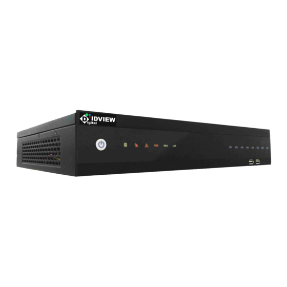
Front Panel The front panel includes: 1. Power button: Power On/Off NVR. 2. IR receiver: Receiver for IR remote. 3. Status indicators: : HDD Indicator turns on when system is accessing hard disk : Alarm indicator turns on when alarm is detected. : Exception indicator turns on when system exception alert is detected, such as disk full, disk error, no disk, network disconnect, illegal login, disk over temperature, fan fail, network fail, power loss and IP conflict. -
Page 11: Rear Panel
Rear Panel The rear panel connectors are: 1. Audio In: Connect the microphone or camera audio output to the audio input connector. 2. Audio Out: Connect a speaker or other audio output device to the audio output connector. 3. VGA: Connect a VGA monitor to the VGA output connector. 4. -
Page 12: Remote Control (Optional)
Remote Control (Optional) The NVR can be operated through the remote controller. The remote control operation is showing in below figure. Batteries (2xAAA) must be installed before operating. 1. ID Button: Press ID button + number key to switch to the NVR that user would like to control. Press a number between 1 and 9 corresponding to the unit ID user wish to control. -
Page 13: General Operation
General Operation Login It is requested to login after boot up if the user authentication is enabled. Click on the User and Password column to bring up the virtual keyboard to enter the preset user account and password to login to the system. The default user name/password is: Administrator: admin/admin Operator: operator/operator... - Page 14 The functions available can be limited by setting passwords. Access to the unit’s functions is determined by the user level of the user logged in. Authority Instructions based on 3 levels of users Administrator Operator Guest View live Live Multiple-up Zoom Pan/Tilt/Zoom (PTZ) Playback...
-
Page 15: Add Ip Cameras To Nvr
Add IP Cameras to NVR 2.2.1 Full Auto Install Mode When the first time connect IP cameras to the NVR, the NVR will pop up install wizard window. NVR provides plug and play feature if user install NVR in “Full Auto Install”... - Page 16 2.2.2 Manual Install Mode If user would like to add IP camera manually, please follow the below steps. Step 1. Click “Manual Install” and press “Next’ to the next page. Step 2. User can configure NVR device settings. User can change the device name, select the desired display language, enable or disable authentication or keep the recorded data in hard disk or not.
- Page 17 Step 3. User can configure network settings for WAN and LAN. The connection of the LAN port is for IP cameras. The connection of the WAN port is for the NVR to Internet. The NVR provides the options for user to access to the NVR through DHCP, Fixed IP or PPPoE.
- Page 18 Step 4. User can configure Date/Time settings of the NVR. After finish the Date/Time settings, please press “Apply” to save user’s changes and proceed to the next step. Adjust Time : Click on the column and the Calendar will pop up on screen for user to adjust the system date and time.
- Page 19 Step 5. After press “Apply” button, the NVR will start to scan the LAN environment to search for the specific IP cameras.
- Page 20 Step 6. After NVR gets the specific IP cameras, it will display the IP camera list. User can click “Add” button to add IP camera into desired channel. Step 7. After adding IP cameras into NVR, NVR will start to configure the parameters of the IP cameras.
- Page 21 Step 8. When NVR finish the configuration of the IP cameras, it will pop up the success message and IP camera also successfully add into NVR.
-
Page 22: Live Viewing
Live Viewing 2.3.1 Basic Operation The NVR will enter into the Live View mode after user login to the system. Use mouse to double click on any video channel to bring it up to full screen display. The basic operation icons are showing on the main screen, the functions are: (A) System indicators, Channel selection and Audio output selection The system indicator is showing general system status for each input channel. - Page 23 Click on the Audio icon on the channel user would like to display, the audio output will switch to the selected channel. (4) To switch channel in the display window, move the focus channel to the selected window, click on the channel button user wish to display, the channel will be switched.
- Page 24 (D) Current streaming information: It indicates the current video streaming resolution, frame rate and data rate. (E) Current date time: It indicates the current system time.
-
Page 25: Search And Playback Operation
Search and Playback Operation 2.4.1 Basic operation To search and playback the video, click “Playback” button on the main page to switch to playback mode as show below. The display mode controls are the same as under Live View mode. The function controls are as below: Click to bring up the Export menu Under full screen mode, click to enable Digital Zoom function. -
Page 26: Calendar
2.3.2 Calendar The calendar on the screen shows the recorded data contains in the hard drives. The date highlighted in orange means there’s recorded data of the date in the hard drives. The red highlighted date indicates the current search date. Click on the calendar to select the date user would like to search. - Page 27 2.3.3.2 Search by Channel Select the channel that user would like search. All the event video files of the selected date and channel will be shown in the list. Select the event video user would like to view and double click the item to start to play on the display window.
-
Page 28: Playback Operation
2.3.4 Playback operation Please refer to the below for the playback control function: 2012-05-28 02:28:58pm The progress bar shows the current playback status and timeline. Drag the time indicator on the progress bar to move to the selected timeline to playback. On the time bar, it also indicates the initial and end time of the current playback section. -
Page 29: Ptz Control
PTZ Control Click on the “PTZ” button to enable the PTZ control panel as shown below. The PTZ control will apply the PTZ command to the current focus camera channel if it’s connected to a PTZ device which include RS485 PTZ device or Network PTZ device. -
Page 30: Export Video
Export Video To export the video from NVR hard disk to external device, click “Export” button to bring up the Export menu shown as below. Connect the external storage device to the USB port on the unit before executing the exporting process. -
Page 31: Export Player
Export Player The Export Player allows user to view video exported from the NVR or Web viewer on a PC. (System operating platform: Windows XP, Windows Vista, or Windows 7.) Player Installation The Export Player can be downloaded from NVR or Web Viewer. On the NVR, insert the USB pen drive then start the Export page as shown below. - Page 32 To open a video export file, click “Open” button to select the exported file. Drag the files to the window that would like to display. The Player will automatically start to play the video. Note: The Player can only play multiple channels that are within the same time duration.
-
Page 33: System Setup Menu
Click to playback video Click to pause video Click to switch to fast forward playback, use to adjust playback speed, in x0.25, x0.5, x1, x2, x4 and x8. Click to stop playback video Click to enable or disable audio playback. Drag the slide bar to adjust the volume. -
Page 34: Camera
Click the “Configuration” button , the setup menu will be enable and shown as below. Please refer to below for the setup menu functions Camera The camera setup menu allows user to configure the behaviors related to the input video of IP cameras. -
Page 35: Settings
6.1.1 Settings In the Camera-Settings menu, it displays the current IP camera information, including camera title, IP address and IP camera connecting status. Click on the for detailed setup of each IP camera. Click on the to delete IP camera. - Page 36 6.1.1.1 Basic Setting In the Camera-Settings-Basic menu, user will see the IP camera basic information and user can configure stream profiles of the IP cameras from the NVR. Camera title – Click on the column, the virtual keyboard will pop-up for user to input the camera title.
- Page 37 User can configure “Frame rate” and “Max Bitrate” of the IP camera from NVR. Note: Once user make the changes of stream profiles, frame rate and max bitrate and click “Apply” to save the new parameters, IP camera will start to proceed the configuration.
- Page 38 6.1.1.2 Advanced Setting In the Camera-Settings-Advanced menu, user can configure video color settings of IP cameras from the NVR. User can adjust video brightness, contrast, saturation, sharpness, mirror and flip of the IP cameras. Press “Exit” to back the previous page.
- Page 39 6.1.1.3 Video Loss Handle Settings In the Camera-Settings-Video Loss Handle Settings menu, it allows user to define the system behaviors while there’s video loss triggered. Buzzer – Select On to trigger buzzer when video loss is detected. Trigger Alarm Out – The corresponding alarm output setting. ...
- Page 40 6.1.1.4 Motion Handle Settings In the Camera-Settings-Motion Handle Settings menu, it allows user to define the system behavior while there’s motion triggered. Enabled – Select On to enable motion handle. Buzzer – Select On to trigger buzzer when motion is detected. ...
- Page 41 6.1.1.5 PTZ settings In the Camera-Settings-PTZ menu, it allows user to configure the settings if the NVR is connected to a RS485 PTZ camera or Network PTZ camera. Enabled – Select On to enable PTZ control. PTZ Type – It will display RS485 PTZ or Network PTZ. It depends on which PTZ type NVR connects.
-
Page 42: Record Settings
6.1.2 Record Settings In the Camera-Record menu, user can define the recording behavior in the record setup menu. Each channel can be configured independently. Click on the selected channel to bring up the setup page. Record Audio – Enable or Disable the audio recording. ... -
Page 43: Schedule Settings
6.1.3 Schedule Settings In the Camera-Schedule menu, user can define the recording schedule and recording behavior for each individual channel in the below page. To setup schedule, select the channel from the left column, the recording option for the channel will be shown in the right column. ... -
Page 44: Network
Network 6.2.1 Network Settings The Network function must be enabled and configured properly in order to access and configure the IP cameras and NVR. 6.2.1.1 In the Network-Settings-WAN menu, user is required to set up the WAN setting properly in order to access NVR via internet. ... - Page 45 6.2.1.2 In the Network-Settings-LAN menu, user is required to set up the LAN setting properly in order to access IP cameras via intranet. The NVR provides the options for DHCP or Fixed IP in LAN environment. Select the option user would like to use to enable and configure the settings. Click “Apply”...
- Page 46 6.2.1.2 DDNS In the Network-Settings-DDNS menu, user can select DDNS to configure the Dynamic DNS. The setup page is shown as below. Select On to enable DDNS. Input DDNS provider and enter the required information. Click “Apply” to save the settings.
-
Page 47: Network Service
6.2.2 Network Service 6.2.2.1 Service In the Network-Service-Service menu, user can enable/disable NTP Server and enable/disable UPnP. User can enable NTP Server to make NVR as NTP Server. After enable NTP Server, IP camera can synchronize the date and time with NVR. ... - Page 48 6.2.2.2 DHCP Server In the Network-Service-DHCP Server menu, user can select on to make NVR as DHCP Server. After enable DHCP Server, NVR is able to assign IP address to IP camera in the LAN environment. The range is from 0 ~ 255. Click “Apply”...
-
Page 49: Network Notification
6.2.3 Network Notification 6.2.3.1 Alarm Notification In the Network-Notification- Alarm Notification, the network alarm can be transmitted to up to 3 addresses. Server IP 1~3 – Input the addresses for system to send the notification. Server port – Select the transmission port for network alarm messages. Click “Apply”... - Page 50 6.2.3.2 E-Mail Notification In the Network-Notification-E-mail Notification menu, user is able to set the Email addresses and input related information. If “Send Email” is enabled in video loss, motion, alarm settings or system exception and when they are being triggered, the e-mail will be sent according to the E-mail notification setting.
-
Page 51: Alarm Settings
Alarm Settings 6.3.1 Alarm Input Settings In the Alarm-Settings menu, user can define the alarm behaviors and the corresponding actions for triggered alarm. Alarm input – Select the alarm input number from 1 to 8, the corresponding settings will show in the window. ... -
Page 52: Exception Management
6.3.2 Exception Management In the Alarm-Exception menu, it allows user to define the system behavior when there’s an exceptional event occurred. The exceptional events are including Disk full, Disk error, No disk, Network Disconnect, Illegal Login, Disk Over Temperature, Fan Fail, Power loss and IP conflict. -
Page 53: System Settings
System Settings 6.4.1 Device Setting In the System-Device menu, user can configure the device related settings. Device Name – Input the name for the NVR. Device No. – Input the number for the NVR. Language – Select from the list for the language to be displayed on the local NVR. ... -
Page 54: User Settings
6.4.2 User Settings User setting page is where user can add or delete users on the system. The default user name and password are as below. Administrator: admin/admin Operator: operator/operator Guest: guest/guest Double click the selected user or click on to edit the user settings. -
Page 55: Date/Time Settings
6.4.3 Date/Time Settings 6.4.3.1 General Setting Adjust Time – Click on the column and the Calendar will pop up on screen for user to adjust the system date and time. Click “Apply” to enable the settings. Time Zone – Set the time zone that the NVR adjusts to when updating from the time server. - Page 56 6.4.3.2 DST Settings (Daylight Saving Time) Enabled – Select On to enable daylight saving time. Start time – Set the start date and time of daylight saving time. End time – Set the end date and time of daylight saving time. ...
- Page 57 6.4.3.3 NTP Client Settings Enabled – Select On to enable NTP synchronization. Sync. Interval (mins) – Input the frequency that the system automatically updates the time. Click the button “Sync. Now” if immediately synchronization is needed. NTP Server – Input the time server address for time synchronization. The default NTP server is “time.stdtime.gov.tw”.
-
Page 58: Display
6.4.4 Display The Display setting allows user to define the monitor output behavior. 6.4.4.1 General Settings In the System-Display-General menu, user can select the proper resolution for connected HDMI and VGA monitors. Monitor Resolution –Select Auto for system to identify resolution automatically for connected HDMI and VGA monitors. - Page 59 6.4.4.2 Main Monitor Settings In the System-Display-Main Monitor menu, user can configure the main monitor display mode and the contents. Sequence enabled – Select On to enable sequence display on main monitor. Dwell – Input the dwell time in seconds for sequence display. ...
-
Page 60: Disk
6.4.5 Disk In the System-Disk menu, user can review and manage the hard disk settings of the NVR. 6.4.5.1 General Settings In the System-Disk-General, user can enable or disable overwrite. The user is also able to select the auto delete days. ... - Page 61 6.4.5.2 Disk Management In the System-Disk-Disk menu, it is to manage and display the information of all the available hard disk. The information is including the hard disk total storage size, current temperature, usage status, available data start/end time. Click “Format”...
-
Page 62: Miscellaneous
6.4.6 Miscellaneous 6.4.6.1 Shutdown In the System-Misc-Shutdown menu, user can select to reboot or shutdown the system from this page. - Page 63 6.4.6.2 Firmware Upgrade In the System-Misc-Firmware upgrade menu, user is able to upgrade NVR firmware by store the firmware in USB drive. To upgrade the firmware, connect a USB flash device which contains the firmware version user would like to update. Click “Upgrade” to start the firmware upgrading. The system reboot is required to complete the firmware upgrade.
-
Page 64: Configuration
6.4.7 Configuration Restore Factory Default– User can load factory default by clicking “Restore” button. Select the items that would like to be excluded from back to the factory default, the selected items will remain as the current values User Configuration –... -
Page 65: Information
Information 6.5.1 General Information In the Information-Information menu, it displays the general system information. The information includes model name, firmware version, serial number, WAN IP address, WAN MAC Address, LAN IP address and LAN MAC address. -
Page 66: Log
6.5.2 In the Information-Log menu, it allows user to filter and review the system event log. Click the date column and the calendar will pop up for user to select the day to be displayed. Click the items user would like to review and to show in the event log. The filtered log will be displayed in the page. -
Page 67: Web Viewer Operation
Web Viewer Operation Connecting to NVR Users can remote access the NVR through Microsoft Internet Explorer to view live/recorded video and manage the NVR. Before accessing the web viewer, make sure that the PC and NVR are both connected to the internet and the network feature is enabled. - Page 68 After installing the Active X, the login page will be displayed for users to enter the User name and Password. Users can also select the OSD language, date format and time format from the login page. Click “Login” to enter the web viewer. The user name/password are the same as the NVR login, the defaults are: Administrator: admin/admin...
-
Page 69: Remote Live View
Remote Live View After login to the system, the web viewer will automatically display a 4-screen live video. Double click on a video display window and it will display full screen in the selected channel. The system indicators on the screen show the system status, channel status and for user to control the audio display channel. - Page 70 Click to switch to Export mode Click to enable the PTZ control panel Click to Logout from the current user’s privilege. Full screen display mode Quad display mode 3+3 display mode Show/Hide OSD Two-way audio Click to take a snapshot of the selected video. In full screen, click to zoom in/out of the selected video in 2x, 4x and 8x.
-
Page 71: Remote Search And Playback
Remote Search and Playback Click the “Playback” button to switch to playback mode. The video can be searched by Time, Channel and Event, select the search type to start searching. 7.4.1 Search by Time The calendar on the screen shows the recorded data contains in the NVR hard drives. The date highlighted in orange means there’s recorded data of the date in the hard drives. -
Page 72: Search By Channel
7.4.2 Search by Channel Search by Channel allows user to search the event video by channel. Select the date from the calendar, and select the channel user would like to view. The event video list of the selected channel will be shown on the screen. Double click on the selected recorded file to start the playback. -
Page 73: Search By Event
7.4.3 Search by Event Search by event allows user to search the event video list by channel and by event type. Select the channel user would like to view (user can also click All On or All off to enable or disable all channels), then select the event type (Alarm, Motion and Video Loss), the event video list of the selected channel and event type will be shown on the screen. -
Page 74: Web Viewer Playback Operation
7.4.4 Web Viewer Playback Operation Click on the “Playback” button to switch to the below menu. The basic Playback operations are as below. The progress bar shows the current playback status and timeline. Drag the time indicator on the progress bar to move to the selected timeline to playback. On the time bar, it also indicates the initial and end time of the current playback section. -
Page 75: Web Viewer Setup Menu
7.4.5 Web Viewer Setup Menu Click on the “Config” button to switch to the setup menu page as below. User can configure all the NVR settings remotely through the web viewer. The setup menu operation is the same as in the NVR. Please refer to the Chapter 6 System Setup Menu for the setup details. -
Page 76: Remote Export
7.4.6 Remote Export Click on the “Export” button to bring up the remote export menu, this allows user to export the video file from the NVR. To export the video, select the date from the calendar, the starting time of the video and channels that user would like to export. - Page 77 User can view the exported file on the Export Player. If the user does not have the Player installed in the PC, click Export Player button to download the player to the PC. Please refer to Chapter 5 for Export Player operation.
-
Page 78: Remote Ptz Control
7.4.7 Remote PTZ Control Click the “PTZ” button to enable the PTZ control panel. This allows user to control the connected PTZ camera. The basic operation is the same as the NVR PTZ control. Please refer to Chapter 3 for detail operation. - Page 79 7.4.8 Remote Snapshot Click the “Snapshot” button in live mode or playback mode to store the current image as a still image and save in the PC folder.
- Page 80 7.4.9 Remote Digital Zoom The function allows user to enlarge the live video at 2x, 4x and 8x in live mode or in playback mode. Move the focus to the selected video. Click “Full Screen” button first and then click “Digital Zoom” icon and the selected area which user would like to enlarge.
-
Page 81: Vs Viewer For Ios And Android
VS Viewer for iOS and Android Android System System requirement To be able to install and run VS viewer, please make sure user’s Android device is running Google Android 2.2 or later, and the device is with wireless network supported. Download the APP Step1. - Page 82 Step3. Tap “VS Viewer” icon to launch the APP. Step4. Tap “Add” to add new NVR. Step5. Input NVR name, Host (IP Address), Port, User name and Password. Tap on “Save” to activate the settings.
- Page 83 To operate the APP Tap on the NVR that user would like to open the view window. Rotate the screen, the orientation of the screen rotates with the tablet as user turn it.
- Page 84 To select the view channel Tap on to switch the display mode between full screen and quad screen display. Select the display mode, and indicate the channel by tap on the number that user would like display in the selected display window. Tap on again to hide the selections.
-
Page 85: Ios System
Others To enable/disable audio display Under full screen mode, tap on the icon to enable the digital zoom function. To operate, place two fingers at once on the display window and pinch them together to zoom out, or spreading them apart to zoom in. The zoom in/out display ratio will be shown on the screen. - Page 86 Step3. Run “VS Viewer” Step4. Tap on to add new NVR. Step5. Input NVR name, Host (IP Address), Port, User name and Password. Tap on “Save” to activate the settings.
- Page 87 To operate the APP Tap on the NVR that user would like to open the view window.
- Page 88 Rotate the screen, the orientation of the screen rotates with the tablet as user turn To select the view channel Tap on to switch the display mode between full screen and quad screen...
- Page 89 display. Select the display mode, and indicate the channel by tap on the number that user would like display in the selected display window. Tap on again to hide the selections. PTZ Control (Reserved) Others To enable/disable audio display Under full screen mode, tap on the icon to enable the digital zoom function. To operate, place two fingers at once on the display window and pinch them together to zoom out, or spreading them apart to zoom in.
-
Page 90: Cms Pro Operation
CMS Pro Operation Begin Installation Simply double click user’s CD-ROM drive icon “Setup.exe” to launch the installer. Once the CMS Pro installer starts, it should begin to check the compatibility with the operating system user are running this installation on. If user are installing the software in Windows XP, Vista, Windows 7, please make sure the software is installed with administrator privilege. - Page 91 If user’s software is without .NET Framework 4.0, the CMS Pro installer will require user to install .NET Framework 4.0 to ensure CMS operation. After click yes, there will pop up the installation progress bar to indicate the progress. The .NET Framework 4.0 installer will ask user to review the license terms. After user accept the license terms, please click “...
- Page 92 Please click “Next” to proceed further.
- Page 93 Once .NET Framework 4.0 software install successfully, it will pop up the below complete message. Then user can begin to install CMS Pro software.
- Page 94 Once the .NET Framework 4.0 install successfully, user can begin the installation by clicking “Next’. The CMS Pro installer will ask user to review the license terms. After user accept the license terms, please click “ I Agree” to proceed further.
- Page 95 The CMS Pro installer will install the program in a default directory. User can either accept the default or choose the directory user would like to save the installer. And click “install” to proceed with the installation. The CMS Pro installer will show the installation process.
-
Page 96: Start Cms Pro From The Pc
Once the installation is complete, click “Finish” to exit the CMS Pro installer. Start CMS Pro from the PC The program automatically creates a shortcut icon on user’s PC after CMS Pro install successfully. Simply double click the icon to launch the program. If user are running the CMS Pro software in Windows XP, Vista and Windows 7, please make sure the software is installed with administrator privilege. -
Page 97: Cms Pro Ui Overview
CMS Pro UI Overview (A) Menu Bar: This is where user can access all functions of the software. (B) Device List: This is where user can add or delete or edit device group. (C) PTZ Control Panel: This is where user can pan, tilt, zoom the selected PTZ cameras. -
Page 98: Login
Login After installing the below digital signature, the login page will be displayed for users to enter the User name and Password. Click “OK” to enter CMS Pro Software. The default user name/password for CMS Pro is: Administrator: admin/admin The program provides multi-language support. To change the display language, please select the desired language from the CMS language drop-down menu. -
Page 99: Connect The Program With Device
Connect the program with device The main purpose of the CMS Pro software is to manage multiple devices. User would need to tell the program which device user need to manage. User do that by adding one or more devices through the device list. 9.5.1 Add Device Manually Click the mouse right button on the “Device List”... -
Page 100: Remove Or Edit Device Setting
9.5.2 Remove or Edit device setting Once user have one or more devices added to the program, the “Edit Device Name”, “Device Setting” and “Delete Device” will become available. Simply click on the mouse right button on the selected device from the list and choose the corresponding buttons to edit device name, edit device setting or delete the device. -
Page 101: Cms Pro Group Video
9.5.3 CMS Pro Group Video User can create the group to contain different videos from different devices. Click the mouse right button on the “Group” and it will pop up “Add Group”. Press “Add Group” and the default “Group 1” will be generated. The group number is increased by numerical order. - Page 102 9.5.3.2 Open Group Stream After finish the edit group content, click “Open Group Stream” on the desired group to play the video streaming. 9.5.3.3 Edit Group Name User can modify the group name. 9.5.3.4 Delete Group User can remove the group from the group list by clicking on the mouse right button on the selected group.
-
Page 103: Live Video
Live Video This page basically provides user the ability to view, and manage the video streams of each channel. The menu bar is available for each video window. The menu bar provides the following functions: The basic operations are showing on the main screen, the functions are: Full screen display mode Quad display mode 9-up screen display mode... - Page 104 Show/Hide OSD Two-way audio Click to take a snapshot of selected live video Click to digital zoom the selected live video Click to stop or play the live video Take a snapshot: The function allows user to take the snapshots of the live video and save them on user’s local computer.
-
Page 105: Playback Video
If user click the “Minimize” icon in the live mode, user will see the icon display on the tool bar of user’s computer. Playback Video The program supports 1 device synchronous playback in full screen or multi-screen view. To start looking for playback videos, click “Playback” button first. - Page 106 Full screen display mode Quad display mode 9-up screen display mode 16-up screen display mode 25-up screen display mode 36-up screen display mode Click to turn on/off recorded audio Show/Hide OSD Two-way audio Click to take a snapshot of selected recorded video Click to digital zoom the selected recorded video Click to stop or play the recorded video If user click the “Minimize”...
-
Page 107: Search For Playback Videos
9.7.1 Search for Playback Videos Simply select a device from the drop-down device list and double click the selected device. It will pop up the calendar. 9.7.1.1 Calendar The calendar on the screen shows the recorded data contains in the hard drives. The date highlighted in red means there’s recorded data of the date in the hard drives. - Page 108 9.7.2.1 Search by Time The recorded section list of the current selected day will be shown on the screen. Double click on the selected recorded file to start the playback. 9.7.2.2 Search by Channel Search by Channel allows user to search the event video by channel. Select the date from the calendar, and select the channel user would like to view.
- Page 110 9.7.2.3 Search by Event Search by event allows user to search the event video list by channel and by event type. Select the channel user would like to view (user can also click All On or All off to enable or disable all channels), then select the event type (Alarm, Motion and Video Loss), the event video list of the selected channel and event type will be shown on the screen.
- Page 111 CMS Playback Operation The basic playback operations are as below. The progress bar shows the current playback status and timeline. Drag the time indicator on the progress bar to move to the selected timeline to playback. On the time bar, it also indicates the initial and end time of the current playback section.
- Page 112 CMS Export Click on the “Export” button to bring up the export menu, this allows user to export the video file from the device To export the video, select the date from the calendar, the starting time of the video and channels that user would like to export.
- Page 113 User can view the exported file on the Export Player. If the user does not have the Player installed in the PC, click Export Player button to download the player to the PC. Please refer to Chapter 5 for Export Player operation.
- Page 114 CMS PTZ Configuration User can synchronize PTZ settings from all cameras connected to the NVR on the network or user can create and add new PTZ preset points to those cameras through CMS Pro. The basic operation is the same as the NVR PTZ control. Please refer to Chapter 3 for detail operation.
- Page 115 9.10 CMS System Click on the “System” button to bring up the system menu, this allows user to change the Date Format, Time Format, Login Authentication and CMS Version. Date Format: Select date format from DD/MM/YYYY, MM/DD/YYYY or YYYY/MM/DD. ...
Need help?
Do you have a question about the Real-time NETWORK VIDEO RECORDER and is the answer not in the manual?
Questions and answers