Toshiba RAS-M10SMUV-E Service Manual
Split type heat pump/cooling only model
Hide thumbs
Also See for RAS-M10SMUV-E:
- Installation manual (224 pages) ,
- Owner's manual (216 pages) ,
- Service manual (86 pages)
Chapters
Table of Contents

Related Manuals for Toshiba RAS-M10SMUV-E


Summary of Contents for Toshiba RAS-M10SMUV-E
-
Page 1: Service Manual
FILE NO. A06-015 SERVICE MANUAL AIR-CONDITIONER SPLIT TYPE INDOOR UNIT Heat Pump Model Cooling Only Model RAS-M10SMUV-E RAS-M10SMUCV-E RAS-M13SMUV-E RAS-M13SMUCV-E RAS-M16SMUV-E RAS-M16SMUCV-E R410A PRINTED IN JAPAN, Apr.,2007 ToMo... -
Page 2: Table Of Contents
ADOPTION OF NEW REFRIGERANT This Air Conditioner is a new type which adopts a new refrigerant HFC (R410A) instead of the conventional refriger- ant R22 in order to prevent destruction of the ozone layer. WARNING Cleaning of the air filter and other parts of the air filter involves dangerous work in high places, so be sure to have a service person do it. -
Page 3: Safety Precautions
1. SAFETY PRECAUTIONS For general public use Power supply cord of outdoor unit shall be 1.5 mm ² (H07RN-F or 60245IEC66) polychloroprene sheathed flexible cord. • Read this “SAFETY PRECAUTIONS” carefully before servicing. • The precautions described below include the important items regarding safety. Observe them without fail. •... - Page 4 • DO NOT INSTALL NEAR CONCENTRATIONS OF COMBUSTIBLE GAS OR GAS VAPORS. FAILURE TO FOLLOW THIS INSTRUCTION CAN RESULT IN FIRE OR EXPLOSION. • TO PREVENT THE INDOOR UNIT FROM OVERHEATING AND CAUSING A FIRE HAZARD, PLACE THE UNIT WELL AWAY (MORE THAN 2 M) FROM HEAT SOURCES SUCH AS RADIATORS, HEAT REGISTORS, FURNACE, STOVES, ETC.
-
Page 5: Specifications
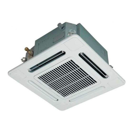
: Combination available, : Combination unavailable This Service Manual describes about 4-way Air Discharge Cassette indoor units, RAS-M10SMUV-E, RAS-M13SMUV-E, RAS-M16SMUV-E, RAS-M10SMUCV-E, RAS-M13SMUCV-E and RAS-M16SMUCV-E only. For the outdoor unit, refer to the Service Manual attached to the combined outdoor unit. -
Page 6: Indoor Unit
2-2. Indoor Unit 2-2-1. Heat Pump Model Indoor unit RAS-M10SMUV-E RAS-M13SMUV-E RAS-M16SMUV-E Model Panel RB-B11MC (W) E Power supply 1 phase, 50Hz 220 to 240 V, 60Hz 220 V Voltage 220/230/240 220/230/240 220/230/240 0.21/0.20/0.19 0.21/0.20/0.19 0.21/0.20/0.19 Running current Electrical characteristics... -
Page 7: Cooling Only Model
2-2-2. Cooling Only Model Indoor unit RAS-M10SMUCV-E RAS-M13SMUCV-E RAS-M16SMUCV-E Model Panel RB-B11MC (W) E Power supply 1 phase, 50Hz 220 to 240 V, 60Hz 220 V Voltage 220/230/240 220/230/240 220/230/240 Running current 0.21/0.20/0.19 0.21/0.20/0.19 0.21/0.20/0.19 Electrical characteristics Power consumption Power factor High (dB) Medium+... -
Page 8: Refrigerant R410A
3. REFRIGERANT R410A This air conditioner adopts the new refrigerant HFC 6. When an air conditioning system charged with a (R410A) which does not damage the ozone layer. large volume of refrigerant is installed in a small room, it is necessary to exercise care so that, The working pressure of the new refrigerant R410A even when refrigerant leaks, its concentration is 1.6 times higher than conventional refrigerant... - Page 9 Table 3-2-1 Thicknesses of annealed copper pipes Thickness (mm) Nominal diameter Outer diameter (mm) R410A 6.35 0.80 0.80 9.52 0.80 0.80 12.70 0.80 0.80 15.88 1.00 1.00 2. Joints For copper pipes, flare joints or socket joints are used. Prior to use, be sure to remove all contaminants. a) Flare Joints Flare joints used to connect the copper pipes cannot be used for pipings whose outer diameter exceeds 20 mm.
- Page 10 d) Flare Processing Make certain that a clamp bar and copper pipe have been cleaned. ØD By means of the clamp bar, perform the flare processing correctly. Use either a flare tool for R410A or conven- tional flare tool. Flare processing dimensions differ according to the type of flare tool.
- Page 11 Table 3-2-6 Flare and flare nut dimensions for R22 Dimension (mm) Nominal Outer diameter Thickness Flare nut width diameter (mm) (mm) (mm) 6.35 9.52 13.0 13.5 12.70 16.2 16.0 12.9 15.88 19.7 19.0 16.0 19.05 23.3 24.0 19.2 Fig. 3-2-2 Relations between flare nut and flare seal surface 2.
-
Page 12: Tools
3-3. Tools 3-3-1. Required Tools The service port diameter of packed valve of the outdoor unit in the air-water heat pump using R410A is changed to prevent mixing of other refrigerant. To reinforce the pressure-resisting strength, flare processing dimensions and opposite side dimension of flare nut (For Ø12.7 copper pipe) of the refrigerant piping are lengthened. -
Page 13: Recharging Of Refrigerant
3-4. Recharging of Refrigerant When it is necessary to recharge refrigerant, charge the specified amount of new refrigerant according to the following steps. Recover the refrigerant, and check no refrigerant remains in the equipment. When the compound gauge’s pointer has indicated –0.1 Mpa (–76 cmHg), place the handle Low in the fully closed position, and turn off the vacuum pump’s power switch. -
Page 14: Brazing Of Pipes
1. Be sure to make setting so that liquid can be charged. 2. When using a cylinder equipped with a siphon, liquid can be charged without turning it upside down. It is necessary for charging refrigerant under condition of liquid because R410A is mixed type of refrigerant. Accordingly, when charging refrigerant from the refrigerant cylinder to the equipment, charge it turning the cylinder upside down if cylinder is not equipped with siphon. - Page 15 2. Characteristics required for flux 3-5-3. Brazing • Activated temperature of flux coincides with As brazing work requires sophisticated techniques, the brazing temperature. experiences based upon a theoretical knowledge, it must be performed by a person qualified. • Due to a wide effective temperature range, flux is hard to carbonize.
-
Page 16: Construction Views
4. CONSTRUCTION VIEWS 4-1. Indoor Unit RAS-M10SMUV-E, RAS-M13SMUV-E, RAS-M16SMUV-E RAS-M10SMUCV-E, RAS-M13SMUCV-E, RAS-M16SMUCV-E 595 to 660 Ceiling open dimension 1000 or more Check port 450) Check port 450) Check port 450) Drain-up standing-up size Obustacle Indoor unit 1000 or more Bottom face... -
Page 17: Refrigerating Cycle Diagram
Outer diameter Ø6.4 Outer diameter A To outdoor unit To outdoor unit Outer diameter A RAS-M10SMUV-E, RAS-M10SMUCV-E Ø9.52 RAS-M13SMUV-E, RAS-M13SMUCV-E Ø9.52 RAS-M16SMUV-E, RAS-M16SMUCV-E Ø12.7 For the outdoor unit, refer to the Service Manual of the combined outdoor unit. -
Page 18: Wiring Diagram
6. WIRING DIAGRAM 6-1. Indoor Unit 6-1-1. 4-way Air Discharge Cassette Type CN34 (RED) CN104 CN102 CN101 (YEL) (RED) (BLK) MCC-5056 CN33 (WHI) Control P.C. Board for CN64 Indoor Unit (GRN) Wireless unit assembly CN60 CN202 CN201 DC20V (WHI) (WHI) (BLU) DC15V DC12V... -
Page 19: Specifications Of Electrical Parts
7. SPECIFICATIONS OF ELECTRICAL PARTS 7-1. Indoor Unit Parts name Type Specifications Fan motor (for indoor) SWF-230-60-1R Output (Rated) 60 W, 220–240 V Thermo. sensor (TA-sensor) 155 mm 10 kΩ at 25°C Heat exchanger sensor (TCJ-sensor) Ø6 mm, 1500 mm 10 kΩ... -
Page 20: Control Block Diagram
8. CONTROL BLOCK DIAGRAM 8-1. Indoor Control Circuit Indoor unit Indoor control P.C. board EEPROM (MCC-5056) Ceiling panel Sensor display TA sensor P.C. board (MCC-5053)) DC5V TC sensor DC12V TCJ sensor Louver Driver motor Float input Outside output Warning Ready Drain Thermo. -
Page 21: Operation Description
9. OPERATION DESCRIPTION • Detection of inverter input current and current 9-1. Outline of Air Conditioner Control release operation This air conditioner is a capacity-variable type air • Over-current detection and prevention operation conditioner, which uses DC motor for the indoor fan to IGBT module (Compressor stop function) motor and the outdoor fan motor. -
Page 22: Operation Description
9-2. Operation Description 9-2. 1. Basic operation ........................23 1. Operation control ....................... 23 2. Operating mode selection when performing 2-room operation ......... 24 3. Cooling/Heating operation ....................24 4. AUTO operation ......................... 25 5. DRY operation ........................25 2. Indoor fan motor control ......................26 <In cooling operation>... -
Page 23: Basic Operation
Item Operation flow and applicable data, etc. Description 1. Basic 1. Operation control operation Receiving the user’s operation condition setup, the operation statuses of indoor/outdoor units are controlled. 1) The operation conditions are selected by the remote controller as shown in the below. 2) A signal is sent by ON button of the remote controller. -
Page 24: Operating Mode Selection When Performing 2-Room Operation
Item Operation flow and applicable data, etc. Description 1. Basic 2. Operating mode selection when performing 2-room operation operation 1) The outdoor unit operating mode conforms to the instructions of the indoor unit that was pressed first. 2) When combined operation consisting of cooling (dry) and heating, fan and heating, or cleaning operation and heating is performed, operation conforms to the instructions of the indoor unit that was pressed first as shown in the following table. -
Page 25: Auto Operation
Item Operation flow and applicable data, etc. Description 1. Basic 4. AUTO operation 1) Detects the room temperature (Ta) when operation the operation started. Selection of operation mode As shown in the following figure, the operation starts by 2) Selects an operation mode from Ta in selecting automatically the status of room temperature the left figure. -
Page 26: Indoor Fan Motor Control
Fig. 2 and Table 1 (Linear approximation +0.5 according to the setup tempera- L(W6) from M+ and L) ture, room temperature, and heat exchanger temperature. (Table 1) Indoor fan air flow rate (Cool/Dry/Fan only) RAS-M10SMUV-E RAS-M13SMUV-E RAS-M16SMUV-E COOL RAS-M10SMUCV-E RAS-M13SMUCV-E RAS-M16SMUCV-E Fan speed level... -
Page 27: In Heating Operation> (Heat Pump Model)
Item Operation flow and applicable data, etc. Description 2. Indoor fan <In heating operation> (Heat pump model) 1) When setting the fan speed to L, motor control L+, M, M+ or H on the remote controller, the operation is per- formed with the constant speed HEAT ON shown in Fig. -
Page 28: Release Protective Control By Temperature Of Indoor Heat Exchanger
Item Operation flow and applicable data, etc. Description 3. Release protective <In cooling/dry operation> 1) When temperature of the indoor control by tempera- heat exchanger drops below 4°C, (Prevent-freezing control for indoor heat exchanger) ture of indoor heat the compressor speed is In cooling/dry operation, the sensor of indoor heat exchanger reduced. -
Page 29: Dain Pump Control
Item Operation flow and applicable data, etc. Description 4. Dain pump In cooling, and dry operation, drain pump is actuated to 1) During cooling, or drying operation: control drain up. Drain pump ON. (Includes period during thermo-OFF) <Operation control> 2) When stopping cooling or dry operation, the drain pump also stops. -
Page 30: Louver Control
Item Operation flow and applicable data, etc. Description 7. Louver control This function controls the air direction of the indoor unit. 1) Louver • The position is automatically controlled according to the operation mode (COOL/HEAT). position • The set louver position is stored in memory by the microcomputer, and the louver returns to the stored position when the next operation is performed. -
Page 31: Eco Operation
Item Operation flow and applicable data, etc. Description 8. ECO Pushing [ECO] button of the remote controller controls the following operation items. 1) During cooling or drying operation Set temperature: Controls with temperature 1.0°C higher than usual. No. of fan revolutions: For No. of fan revolutions, the automatic operation that M tap is at upper limit is performed. -
Page 32: Forced Operation Stop Switch
Item Operation flow and applicable data, etc. Description 11. Forced This function controls the indoor units individually. The operation of the indoor operation stop unit can be forcedly stopped It is connected with cable to the control P.C. board of the indoor unit. switch when opening the window by 1. -
Page 33: Indoor Fan On Output
Item Operation flow and applicable data, etc. Description 12. Indoor fan ON signal is output when the indoor fan is operating. A fan or etc can be used by ON output synchronized with the indoor unit. 1. Control items • While the indoor fan is operating, DC12V is output between 1 and 6 of CN60. -
Page 34: Select Switch On Remote Controller
Item Operation flow and applicable data, etc. Description 13. Select switch on 1. Setting remote controller 1. Purpose remote controller • Remove the cover, and insert the batteries. This operation is to operate only one indoor unit using one remote •... -
Page 35: Auto Restart Function
Item Operation flow and applicable data, etc. Description 14. Auto restart This product is designed so that, after a power failure, it can restart automatically in the same function operating mode as before the power failure. INFORMATION The product was shipped with Auto Restart function in the OFF position. Turn it ON as required. -
Page 36: Setting Temperature Correction Switch
Item Operation flow and applicable data, etc. Description 16. Setting tem- 1. To improve Cooling/Heating effect perature When only poor cooling/heating effect is obtained due to installation place of the indoor unit or correction construction of the room, the detection temperature of cooling/heating can be changed. switch •... -
Page 37: Intermittent Operation Control For Indoor Fans Of The Indoor Unit At Thermo-Off Side In Heating Operation
9-3. Intermittent Operation Control for Indoor Fans of the Indoor Unit at Thermo-off Side in Heating Operation While heating operation is executed in two rooms, if room temperature reached the setup temperature in one room and thermo-off occurred, the following operations start. (Refer to the figure below.) 1. -
Page 38: Remote Controller
9-4. Remote Controller 9-4-1. Parts Name of Remote Controller High power button (Hi POWER) START/STOP button Push this button to start the high power operation. Push the button to start operation. (A receiving beep is heard.) Memory button (MEMO) Push the button again to stop operation. Push this button to store the settings. -
Page 39: Names And Functions Of Indications On Remote Controller
9-4-2. Names and Functions of Indications on Remote Controller Display All indications, except for clock time indication, are indicated by pushing the START/STOP button. Transmission mark High power display This transmission mark indicates when the Indicates when the High power operation starts. remote controller transmits signals to the indoor Push the Hi-POWER button to start and push it unit. -
Page 40: Installation Manual
Connecting pipe (Gas side) Thermal insulation for refrigerant pipe (10 mm or more, thermal insulating foam polyethylene) (9.5 mm (diam.), Nominal (diam.) 3/8” thick 0.8 mm) RAS-M10SMUV-E, RAS-M10SMUCV-E, Thermal insulation for drain pipe RAS-M13SMUV-E, RAS-M13SMUCV-E (10 mm or more, foam polyethylene) (12.7 mm (diam.), Nominal (diam.) 1/2”... -
Page 41: Precautions For Safety
PRECAUTIONS FOR SAFETY • Ensure that all Local, National and International regulations are satisfied. • Read this “PRECAUTIONS FOR SAFETY” carefully before Installation. • The precautions described below include the important items regarding safety. Observe them without fail. • After the installation work, perform a trial operation to check for any problem. Follow the Owner’s Manual to explain how to use and maintain the unit to the customer. - Page 42 • After unpacking the unit, examine for possible damage. • Do not install in a place that might increase the vibration of the unit. • To avoid personal injury (with sharp edges), be careful when handling parts. • Perform installation work properly according to the Installation Manual. Incorrect installation may result in water leakage, electric shock or a fire.
-
Page 43: Selection Of Installation Place
SELECTION OF INSTALLATION PLACE WARNING • The air conditioner must be installed in a location that can support the weight of the unit effectively. If the unit is not installed on a foundation that can support its weight effectively, the unit may fall down, resulting in possible human injury. - Page 44 : 23°C or more) may generate dew inside When changing the setting of the ceiling height in the the ceiling. models, RAS-M10SMUV-E, M10SMUCV-E, M13SMUV-E and M13SMUCV-E, if it is set over 1. Unit is installed inside the ceiling with slated roof.
-
Page 45: Installation Of Indoor Unit
SELECTION OF INSTALLATION PLACE WARNING Install the air conditioner certainly to sufficiently withstand the weight. If the strength is insufficient, the unit may fall down resulting in human injury. Perform a specified installation work to guard against an earthquake. An incomplete installation can cause accidents by the units falling and dropping. Remote controller •... - Page 46 For branch duct knockout square hole 150 diam. 575 Unit external dimension 139.5 Refrigerant pipe (Gas) 12.7 diam. 190.5 RAS-M16SMUV-E RAS-M16SMUCV-E For branch ductt Bottom face of ceiling 9.5 diam. knockout square RAS-M10SMUV-E, M13SMUV-E hole 150 diam. RAS-M10SMUCV-E, M13SMUCV-E – 46 –...
- Page 47 INSTALLATION OF INDOOR UNIT Ceiling opening and installation of hanging bolts • Evaluate and determine the piping and wiring requirements inside the ceiling prior to the hanging of the unit. • After installation place of the indoor unit has been determined, create opening in ceiling and install the hanging bolts.
- Page 48 Installation of indoor unit • Attach the nut (M10 or W3/8: Procured locally) and washer Hanging bolt (34 mm (diam.)) to the hanging bolt. M10 flat washer (W3/8 or M10) (Accessory) • Put washers at either side of the T-groove on the hanging bracket of the indoor unit in order to hang the unit.
-
Page 49: Drain Piping Work
DRAIN PIPING WORK Pipe material / Insulator and size CAUTION The following materials for piping work and insulation • Install the drain piping so that the water are to be procured locally. drains effectively. Hard vinyl chloride pipe socket for VP25 •... - Page 50 Connection of drain pipe Check the draining • Connect the hard socket (Procured locally) to the After completion of drain piping, hard socket side of the supplied flexible hose which Check water drains away and that no water leaks has been installed. from any of the connecting parts.
- Page 51 DRAIN PIPING WORK Thermal insulating process • After checking the draining, wrap the supplied thermal insulation material for the drain connecting part around the flexible hose leaving no clearance from the root of the drain pipe connecting port of the indoor unit. •...
-
Page 52: Refrigerant Piping And Evacuating
REFRIGERANT PIPING AND EVACUATING • Flaring diam. meter size : Refrigerant piping A (Unit : mm) 1. If the outdoor units are to be mounted on a wall, make sure that the supporting platform is sufficiently strong. The platform should be - 0.4 designed and manufactured to maintain its Outer diam. -
Page 53: Evacuating
EVACUATING Packed valve handling precautions AIR PURGE • Open the valve stem until it touches the stopper. Evacuate the air in the connecting pipes and in the indoor unit using vacuum pump. Once it is in contact with the stopper, refrain from applying any more force than is necessary. -
Page 54: Electrical Work
ELECTRICAL WORK WARNING 1. Using the specified wires, ensure to connect the wires, and fix wires securely so that the external tension to the wires do not affect the connecting part of the terminals. Incomplete connection or fixation may cause a fire, etc. 2. - Page 55 ELECTRICAL WORK Wire connection REQUIREMENT • Be sure to connect the wires matching the terminal numbers. Incorrect connection causes a trouble. • Be sure to pass the cables through the bushing of wiring connection port of the indoor unit. • Keep a margin (Approx. 100mm) on a wire to hang down the electric parts box at servicing, etc. •...
- Page 56 Wiring Wiring diagram 1. Remove a screw and then remove cover of the electric parts box. 2. Strip wire ends (10 mm). Indoor side 3. Match wire colors with terminal numbers on indoor and outdoor units’ terminal blocks and firmly screw wires to the corresponding terminals.
-
Page 57: Applicable Controls
APPLICABLE CONTROLS Remote controller selector switch setting • If two indoor units are installed in the same room or adjoining rooms, when the user tries to operate only one unit, both units may receive the same remote controller signal and operate. This can be prevented by changing one of the indoor units and remote controllers to setting “B”... - Page 58 To improve Cooling/Heating effect When only poor cooling/heating effect is obtained due to installation place of the indoor unit or construction of the room, the detection temperature of cooling/heating can be changed. • Remove the cover of the electric parts box by taking off the mounting screws (3 positions) and pushing the hooking section.
-
Page 59: Test Operation
TEST OPERATION Test operation Check and Test operation • To test the system, push and hold RESET button for Be sure to test the piping connections for gas leak. 10 sec. (There will be one short beep.) • Check the flare nut connections, valve stem cap connections and service port cap connections for gas leak with a leak detector or soap water. -
Page 60: Maintenance
MAINTENANCE Prior to maintenance, ensure the power supply is turned off. WARNING CAUTION Cleaning of the air filter and other parts of the air filter Do not handle the buttons with wet hands involves dangerous work in high places, so be sure to as this will cause the risk of electric shock. -
Page 61: How To Diagnose The Trouble
11. HOW TO DIAGNOSE THE TROUBLE Table 11-1 Troubleshooting Procedure Page First Confirmation Primary Judgment Judgment by Flashing LED of Indoor Unit (Switch Panel) Self-Diagnosis by Remote Controller (Check Code) Judgment of Trouble by Every Symptom How to Check Simply the Main Parts P .C. -
Page 62: Primary Judgment
11-2. Primary Judgment To diagnose the troubles, use the following methods. (1) Judgment by flashing LED of indoor unit (2) Self-diagnosis by service check remote controller (3) Judgment of trouble by every symptom Firstly use the method (1) for diagnosis. Then, use the method (2) or (3) to diagnose the details of troubles. For any trouble occurred at the outdoor unit side, detailed diagnosis is possible by 5-serial LED on the inverter P .C. -
Page 63: Self-Diagnosis By Remote Controller (Check Code)
11-4. Self-Diagnosis by Remote Controller (Check Code) 1. The self-diagnosis by the check code is performed while items B to E blocks are displayed. 2. When turning the operation mode on the remote controller to the service mode, and operating the remote controller, the controller of the indoor unit can self-diagnose operation of the protection circuit by displayed contents (check code) on the remote controller, by whether all the lamps flash (5Hz) and the receiving sound (Beep, Beep, Beep ... - Page 64 11-4-2. Caution at Servicing 1. After servicing, push the START/STOP button to return to the normal mode. 2. After servicing by the check code, turn off breaker of the power supply, and turn on breaker of the power supply again so that memory in the microcomputer returns the initial status. However, the check codes are not deleted even if the power supply is turned off because they are stored in the fixed memory.
- Page 65 Block distinction Operation of diagnosis function Judgment and action Check Check Block Cause of operation conditioner Remarks code code status Outdoor P.C. Inverter over-current All off Displayed when Even if trying operation again, all board protective circuit error is detected. operations stop immediately.
-
Page 66: Judgment Of Trouble By Every Symptom
11-5. Judgment of Trouble by Every Symptom 11-5-1. Indoor Unit (Including Remote Controller) (1) Power is not turned on (Does not operate entirely) <Primary check> 1. Is the supply voltage normal? Operation 2. Is the normal voltage provided to the outdoor unit? 3. - Page 67 (3) The indoor fan motor does not operate. Turn off the power. Are not there connections errors or Correct connection of connector. disconnection on connectors CN333 and CN334 of indoor unit P.C. board (MCC-5056)? Remove connectors CN333 and CN334 of indoor unit P.C. board (MCC-5056).
- Page 68 (4) Troubleshooting for remote controller <Primary check> Check that A or B selected on the main unit is matched with A or B selected on the remote controller. The unit does not beep at all. Press the Operation lamp on indoor START/STOP button.
- Page 69 11-5-2. Wiring Failure (Interconnecting and Serial Signal Wire) (1) Outdoor unit does not operate ‚ ƒ 1) Is the voltage between of the indoor terminal block varied? Confirm that transmission from indoor unit to outdoor unit is correctly performed based upon the follow- ing diagram.
-
Page 70: How To Check Simply The Main Parts
11-6. How to Check Simply the Main Parts 11-6-1. How to Check the P.C. Board (Indoor Unit) (1) Operating precautions 1) When removing the electric parts box or the P .C. board, be sure to shut off the power supply breaker. 2) When removing the P .C. -
Page 71: Board Layout
11-7. P.C. Board Layout – 71 –... -
Page 72: Service P.c. Board Selection Information
ON: Remote controller B setting Jumper setup J800, J801, J802, J803 : For the following models, set up jumpers according to the table. ¡ × : Provided (Original) : None (Cut) Model name RAS-M10SMUV-E RAS-M13SMUV-E RAS-M16SMUV-E Status at shipment RAS-M10SMUCV-E RAS-M13SMUCV-E RAS-M16SMUCV-E from factory Part No. -
Page 73: Detachments
12. DETACHMENTS 12-1. Indoor Unit Ceiling panel: RBC-UM11PG(W)E Preparing work: 1. Before work, be sure to stop the power supply of the air conditioner and turn off switch of the power supply breaker. (Otherwise an electric shock may be caused.) 2. - Page 74 Part name Procedure Remarks 1. Detachment Adjust corner cover 1) Perform work of procedure of 2) Turn clockwise screws (4 positions) at the suction port corner until adjust corner cover rises up. NOTE) When you work, keep the torque at below 12N•m. Do not use an electric screwdriver;...
- Page 75 Part name Procedure Remarks 1. Detachment Control P.C. board 1) Perform works of procedure -1- and 2) Remove the connectors connected from the control P .C. board to other parts. CN33 : Flap motor (5P, White) CN34 : Float switch (3P , Red) CN68 : Drain pump (3P , Blue) CN67 : Terminal block of power supply (5P, Black) CN101 : TC sensor (2P, Black)
- Page 76 Part name Procedure Remarks 1. Detachment Electric parts box 1) Perform works of procedure -1-and 2) Remove connectors of the lead wire connected to the following connectors of the control P.C. board. CN33 : Flap motor (5P, White) CN34 : Float switch (3P, Red) CN68 : Drain pump (3P, Blue) CN101 : TC2 sensor (2P, Black) CN102 : TCJ sensor (2P, Red)
- Page 77 Part name Procedure Remarks 1. Detachment Bell mouth 1) Perform work of procedure Fixing claws 2) Take off the lead wires of the drain pump, float for lead wires Bell mouth switch, and fan motor from the bell mouth. 3) Take off fixing screws of the bell mouth. (Ø4 ×...
- Page 78 Part name Procedure Remarks 1. Detachment Fan motor Fixing nut for fan motor 1) Perform work of procedure 2) Take off screws fixed with lead holding bracket of the fan motor. (Ø4 × 10, 2 pcs.) 3) Open wiring holding part of the fan motor lead holding bracket and then take off the fan motor lead wire from the bracket.
- Page 79 Part name Procedure Remarks 1. Detachment Drain pan 2 screws 1) Perform works of procedure -1 and 2) Remove the drain cap and extract drain water accumulated in the drain pan. NOTE) Socket of dr Socket of drain pan et of drain pan ain pan When removing the drain cap, be sure to receive drain water with a bucket, etc.
- Page 80 Part name Procedure Remarks 1. Detachment Heat exchanger 1) Recover refrigerant gas. 2) Remove the refrigerant pipe at indoor unit side. 3) Perform work of procedure Piping cover Piping cover 4) Take off screws (Ø4 × 10, 3 pcs.) fixing the piping cover to remove the piping cover.
-
Page 81: Exploded Views And Parts List
13. EXPLODED VIEWS AND PARTS LIST 13-1. Ceiling Panel RB-B11MC(W)E Location Location Part No. Description Part No. Description 43109414 Grille, Air Inlet 43122092 Joint, Kit (B) 4302D003 Motor, Louver 43122093 Louver 43180332 Air Filter 43107261 Outlet, Air Form 43497012 Screw 43100412 Panel 43100322... -
Page 82: 4-Way Air Discharge Cassette Type
14-2. 4-way Air Discharge Cassette Type RAS-M10SMUV-E RAS-M13SMUV-E RAS-M10SMUCV-E RAS-M13SMUCV-E RAS-M16SMUV-E 238, 240 RAS-M16SMUCV-E RAS-M10SMUV-E,RAS-M13SMUV-E, RAS-M16SMUV-E, RAS-M10SMUCV-E, RAS-M13SMUCV-E RAS-M16SMUCV-E – 82 –... - Page 83 Location Part No. Description 43120225 Fan Ass’y, Turbo 43122094 Bell Mouth 43172185 Pan Ass’y, Drain 43121738 Motor, Fan, SWF-230-60-1R 43044835 Refrigeration, Cycle Ass’y (M10SMUV-E, M13SMUV-E, M10SMUCV-E, M13SMUCV-E) 43044836 Refrigeration, Cycle Ass’y (M16SMUV-E, M16SMUCV-E) 43047691 Distributor Ass’y 43049782 Socket 43047685 Nut, Flare, 1/4 IN 43149355 Nut, Flare, 3/8 IN 43149351...
- Page 84 Location Location Part No. Description Part No. Description 43050425 Sensor Ass’y, Service 4306S935 P .C. Board Ass’y, TC, TCJ (F6) MMC-5056 (220V – 240V) 43050426 Sensor, Service, TA 43160565 Terminal Block, 3P , AC250V, 20A – 84 –...
- Page 85 WARNINGS ON REFRIGERANT LEAKAGE Important Check of Concentration Limit NOTE 2 : The room in which the air conditioner is to be installed requires a design that in the event of The standards for minimum room volume are as follows. refrigerant gas leaking out, its concentration will not (1) No partition (shaded portion) exceed a set limit.
- Page 86 TOSHIBA CARRIER CORPORATION 2 CHOME 12-32, KONAN, MINATOKU, TOKYO, 108-0075, JAPAN Copyright © 2007 TOSHIBA CARRIER CORPORATION, ALL Rights Reserved.
Need help?
Do you have a question about the RAS-M10SMUV-E and is the answer not in the manual?
Questions and answers