Cisco UCS C24 Installation And Service Manual
Hide thumbs
Also See for UCS C24:
- Installation and service manual (156 pages) ,
- Installation and service manual (128 pages)
Table of Contents
Advertisement
Quick Links
Advertisement
Table of Contents

Related Manuals for Cisco UCS C24


Summary of Contents for Cisco UCS C24
- Page 1 Cisco UCS C24 Server Installation and Service Guide Covers Server Generation M3 November 16, 2012 Americas Headquarters Cisco Systems, Inc. 170 West Tasman Drive San Jose, CA 95134-1706 http://www.cisco.com Tel: 408 526-4000 800 553-NETS (6387) Fax: 408 527-0883 OL-26647-01 Text Part Number:...
- Page 2 Cisco and/or its affiliates in the United States and certain other countries. Cisco and the Cisco Logo are trademarks of Cisco Systems, Inc. and/or its affiliates in the U.S. and other countries. A listing of Cisco's trademarks can be found at www.cisco.com/go/trademarks.
-
Page 3: Table Of Contents
Procedure 2: Use Recovery Jumper and recovery.cap File 2-16 Using the Clear CMOS Header CN14 2-17 Maintaining the Server C H A P T E R Server Monitoring and Management Tools Cisco UCS C24 Server Installation and Service Guide OL-26647-01... - Page 4 Replacing a SuperCap Power Module (RAID Backup Unit) 3-34 Replacing a Cisco USB Flash Drive 3-36 Overview of the Pre-Loaded 16-GB Cisco USB Flash Drive 3-36 Enabling a Pre-Loaded Cisco USB Flash Drive Virtual Drive 3-36 Booting a Pre-Loaded Cisco USB Flash Drive Virtual Drive...
- Page 5 SFF 24-Drive Backplane With Expander Cabling LSI MegaRAID Card Beep Codes Restoring RAID Configuration After Replacing a RAID Controller For More Information Installation for Cisco UCS Integration A P P E N D I X Cisco UCS C24 Server Installation and Service Guide OL-26647-01...
- Page 6 Contents Cisco UCS C24 Server Installation and Service Guide OL-26647-01...
-
Page 7: Related Documentation
Preface This preface describes the audience, organization, and conventions of the Cisco UCS C24 Server Installation and Service Guide. It also provides information about how to obtain related documentation. Related Documentation The documentation set for the Cisco Unified Computing System (UCS) C-Series rack-mount servers is... -
Page 8: Documentation Feedback
Preface Audience This guide is for experienced network administrators who configure and maintain Cisco servers. Documentation Feedback To provide technical feedback on this document, or to report an error or omission, please send your comments to ucs-docfeedback@external.cisco.com. We appreciate your feedback. - Page 9 å forhindre ulykker. Bruk nummeret i slutten av hver advarsel for å finne oversettelsen i de oversatte sikkerhetsadvarslene som fulgte med denne enheten. TA VARE PÅ DISSE INSTRUKSJONENE Cisco UCS C24 Server Installation and Service Guide OL-26647-01...
- Page 10 Använd det nummer som finns i slutet av varje varning för att hitta dess översättning i de översatta säkerhetsvarningar som medföljer denna anordning. SPARA DESSA ANVISNINGAR Cisco UCS C24 Server Installation and Service Guide viii OL-26647-01...
- Page 11 Brug erklæringsnummeret efter hver advarsel for at finde oversættelsen i de oversatte advarsler, der fulgte med denne enhed. GEM DISSE ANVISNINGER Cisco UCS C24 Server Installation and Service Guide OL-26647-01...
- Page 12 Preface Cisco UCS C24 Server Installation and Service Guide OL-26647-01...
-
Page 13: Obtaining Documentation And Submitting A Service Request
Obtaining Documentation and Submitting a Service Request For information on obtaining documentation, submitting a service request, and gathering additional information, see the monthly What’s New in Cisco Product Documentation, which also lists all new and revised Cisco technical documentation, at: http://www.cisco.com/en/US/docs/general/whatsnew/whatsnew.html... - Page 14 Preface Cisco UCS C24 Server Installation and Service Guide OL-26647-01...
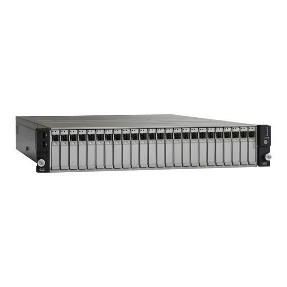
- Page 15 C H A P T E R Overview This chapter provides an overview of the Cisco UCS C24 server features. The figures in this chapter show an overview of external server features. Internal server features are illustrated in Figure 3-4 on page 3-9.
-
Page 16: Chapter 1 Overview
PCIe Slots, page 3-31 for slot specifications. USB 2.0 ports (four) PCIe slots 1 and 2 on riser 1 PCIe Slots, page 3-31 for slot specifications. Serial port (DB-9 connector) – Cisco UCS C24 Server Installation and Service Guide OL-26647-01... - Page 17 The server can be ordered with an optional blank 8-GB Cisco USB Flash Drive pre-installed in the internal USB port. Cisco USB Flash The server can be ordered with one pre-loaded 16-GB Cisco USB flash drive in the Drive accessory kit.
- Page 18 1. DIMM = dual inline memory module 2. VGA = video graphics array 3. USB = universal serial bus 4. PCIe = peripheral component interconnect express 5. RAID = redundant array of independent disks Cisco UCS C24 Server Installation and Service Guide OL-26647-01...
-
Page 19: Installing The Server
Use the statement number provided at the end of each warning to locate its translation in the translated safety warnings that accompanied this device. Statement 1071 SAVE THESE INSTRUCTIONS Cisco UCS C24 Server Installation and Service Guide OL-26647-01... -
Page 20: Chapter 2 Installing The Server
Figure 2-1 Shipping Box Contents PCIe 4 PCIe 3 PCIe 1 PSU 2 PCIe 5 PCIe 2 PSU 1 PSU 1 PSU 1 Server Documentation Power cord (optional, up to two) – Cisco UCS C24 Server Installation and Service Guide OL-26647-01... -
Page 21: Preparing For Server Installation
Avoid UPS types that use ferroresonant technology. These UPS types can become unstable with systems Caution such as the Cisco UCS, which can have substantial current draw fluctuations from fluctuating data traffic patterns. Cisco UCS C24 Server Installation and Service Guide... -
Page 22: Rack Requirements
The minimum vertical rack space per server must be one RU, equal to 1.75 in. (44.45 mm). Equipment Requirements The slide rails supplied by Cisco Systems for this server do not require tools for installation. The inner rails (mounting brackets) are pre-attached to the sides of the server. -
Page 23: Installing The Server In A Rack
Use your finger to hold the rear securing latch open when you insert the rear mounting pegs to their holes. When you release the latch, it wraps around the rack post and secures the slide-rail assembly. Cisco UCS C24 Server Installation and Service Guide OL-26647-01... - Page 24 The inner rails are pre-attached to the sides of the server at the factory. You can order replacement inner rails if these are damaged or lost (Cisco PID UCSC-RAIL1-I). Align the inner rails that are attached to the server sides with the front ends of the empty slide rails.
- Page 25 Flange on rear of right mounting bracket Outer CMA arm attachment clip Flange on rear of outer right slide rail Continue with the “Initial Server Setup” section on page 2-8. Step 5 Cisco UCS C24 Server Installation and Service Guide OL-26647-01...
-
Page 26: Initial Server Setup
DHCP is enabled. Shared LOM EXT mode enables the 1-Gb Ethernet ports and the ports on any installed Cisco virtual interface card (VIC) to access the Cisco Integrated Management Interface (CIMC). If you want to use the dedicated management ports to access the CIMC, you can... - Page 27 Cisco card connection is not getting its IP address from a Cisco UCS Manager system because the server is in standalone mode, further DHCP requests from the Cisco card are disabled. Use the Cisco Card NIC mode if you want to connect to the CIMC through a Cisco card in standalone mode.
-
Page 28: Nic Modes And Nic Redundancy Settings
LOM and Cisco Card interfaces are both enabled. In this mode, DHCP replies are returned to both the shared LOM ports and the Cisco card ports. If the system determines that the Cisco card connection is not getting its IP address from a Cisco UCS Manager system because the server is in standalone mode, further DHCP requests from the Cisco card are disabled. -
Page 29: System Bios And Cimc Firmware
See the Cisco Host Upgrade Utility Quick Reference Guide for your firmware level at the documentation roadmap link below. Your system firmware must be at minimum level 1.2 to use the Cisco Host Upgrade Utility. If Note your firmware is prior to level 1.2, you must use the methods below to update the BIOS and CIMC firmware individually. -
Page 30: Accessing The System Bios
Step 6 Follow the instructions on the Exit menu screen to save your changes and exit the setup utility (or Press F10). You can exit without saving changes by pressing Esc. Cisco UCS C24 Server Installation and Service Guide 2-12 OL-26647-01... -
Page 31: Service Headers And Jumpers
SYS FAN2 Port 1 SYS FAN3 CPU 2 SYS FAN4 Port 0 PSU 1 (bottom) PSU 2 (top) 3 2 1 3 2 1 CN34 BIOS Recovery CN14 Clear CMOS Cisco UCS C24 Server Installation and Service Guide 2-13 OL-26647-01... -
Page 32: Using The Bios Recovery Header Cn34
System would flash the BIOS image now... System would restart with recovered image after a few seconds... Wait for server to complete the BIOS update, then remove the USB thumb drive from the server. Step 6 Cisco UCS C24 Server Installation and Service Guide 2-14 OL-26647-01... - Page 33 During the BIOS update, the CIMC will shut down the server and the screen will be blank for about 10 minutes. Do not unplug the power cords during this update. The CIMC will power on the server after the update is complete. Cisco UCS C24 Server Installation and Service Guide 2-15 OL-26647-01...
-
Page 34: Procedure 2: Use Recovery Jumper And Recovery.cap File
Replace the top cover, replace the server in the rack, replace power cords and any other cables, then Step 14 power on the server by pressing the Power button. Cisco UCS C24 Server Installation and Service Guide 2-16 OL-26647-01... -
Page 35: Using The Clear Cmos Header Cn14
Replace the top cover, replace the server in the rack, replace power cords and any other cables, then Step 11 power on the server by pressing the Power button. Cisco UCS C24 Server Installation and Service Guide 2-17 OL-26647-01... - Page 36 Chapter 2 Installing the Server Service Headers and Jumpers Cisco UCS C24 Server Installation and Service Guide 2-18 OL-26647-01...
-
Page 37: Server Monitoring And Management Tools
Server Monitoring and Management Tools Cisco Integrated Management Interface (CIMC) You can monitor the server inventory, health, and system event logs by using the built-in Cisco Integrated Management Controller (CIMC) GUI or CLI interfaces. See the user documentation for your firmware release at the following URL: http://www.cisco.com/en/US/products/ps10739/products_installation_and_configuration_guides_list.html... -
Page 38: Status Leds And Buttons
Off—The Ethernet link is idle. • Green—One or more Ethernet LOM ports are link-active, but there is no activity. • Green, blinking—One or more Ethernet LOM ports are link-active, with activity. • Cisco UCS C24 Server Installation and Service Guide OL-26647-01... -
Page 39: Chapter 3 Maintaining The Server
Amber—The server is in standby power mode. Power is supplied only to the CIMC • and some motherboard functions. Green—The server is in main power mode. Power is supplied to all server • components. Cisco UCS C24 Server Installation and Service Guide OL-26647-01z... -
Page 40: Rear Panel Leds And Buttons
Green, blinking—Traffic is present on the active link. • 10/100/1000 Ethernet dedicated • Off—link speed is 10 Mbps. management link speed • Amber—link speed is 100 Mbps. • Green—link speed is 1 Gbps. Cisco UCS C24 Server Installation and Service Guide OL-26647-01... - Page 41 Green—Link is active. • Green, blinking—Traffic is present on the active link. • Identification Off—The Identification LED is not in use. • Blue—The Identification LED is activated. • Cisco UCS C24 Server Installation and Service Guide OL-26647-01z...
-
Page 42: Preparing For Server Component Installation
Emergency shutdown—Press and hold the Power button for 4 seconds to force the main power off • and immediately enter standby mode. Disconnect the power cords from the power supplies in your server to completely power off the server. Step 3 Cisco UCS C24 Server Installation and Service Guide OL-26647-01... -
Page 43: Removing And Replacing The Server Top Cover
Tighten the two captive thumbscrews that secure the rear edge of the cover to the chassis. Figure 3-3 Removing the Top Cover or Front Chassis Panel Front chassis panel Top cover Front chassis panel securing screws (three) Top cover thumbscrews (two) Cisco UCS C24 Server Installation and Service Guide OL-26647-01z... -
Page 44: Removing And Replacing The Front Chassis Panel
Replace the three screws that secure the panel to the chassis (see Figure 3-3). Replace the top cover to the server as described in Removing and Replacing the Server Top Cover, page 3-7. Cisco UCS C24 Server Installation and Service Guide OL-26647-01... -
Page 45: Replaceable Component Locations
PCIe riser 1 (two full-height slots) Serial Number Location The serial number for the server is printed on a label on the top of the server, near the front. Cisco UCS C24 Server Installation and Service Guide OL-26647-01z... -
Page 46: Color-Coded Touch Points
(An exception is the drive trays on the front panel, which are hot-swappable but not green). Some replaceable but non-hot-swappable components have light-blue plastic touch-points. • Cisco UCS C24 Server Installation and Service Guide 3-10 OL-26647-01... -
Page 47: Installing Or Replacing Server Components
Replacing a SuperCap Power Module (RAID Backup Unit), page 3-34 • Replacing a Cisco USB Flash Drive, page 3-36 Installing a Trusted Platform Module, page 3-40 • Replacing Power Supplies, page 3-43 • Cisco UCS C24 Server Installation and Service Guide 3-11 OL-26647-01z... -
Page 48: Replacing Hard Drives Or Solid State Drives
With the ejector lever on the drive tray open, insert the drive tray into the empty drive bay. Push the tray into the slot until it touches the backplane, then close the ejector lever to lock the drive in place. Cisco UCS C24 Server Installation and Service Guide 3-12 OL-26647-01... -
Page 49: Replacing A Drive Backplane
Remove all drives and any empty drive trays from the server. Step 2 Disconnect all cables from the backplane. Step 3 Label the cables as you remove them to aid replacement. Cisco UCS C24 Server Installation and Service Guide 3-13 OL-26647-01z... - Page 50 Port 1 SYS FAN3 PCIe riser 2 CPU 2 SYS FAN4 Port 0 PSU 1 (bottom) PSU 2 (top) 1 Backplane assembly securing screws (two) 2 SAS expander securing screws (three) Cisco UCS C24 Server Installation and Service Guide 3-14 OL-26647-01...
-
Page 51: Replacing A Sas Expander
Replace the front chassis panel. Step 7 Replace the top cover. Step 8 Replace the server in the rack, replace cables, and then power on the server by pressing the Power button. Cisco UCS C24 Server Installation and Service Guide 3-15 OL-26647-01z... -
Page 52: Replacing Fan Modules
Slide the server out the front of the rack far enough so that you can remove the top cover. You might have to detach cables from the rear panel to provide clearance. Cisco UCS C24 Server Installation and Service Guide 3-16... - Page 53 Port 0 PSU 1 (bottom) PSU 2 (top) Fan tray connector (one on each fan module) 3 Connector on underside of fan module Finger latches (two on each fan module) Cisco UCS C24 Server Installation and Service Guide 3-17 OL-26647-01z...
-
Page 54: Replacing Dimms
DIMMs and their sockets are fragile and must be handled with care to avoid damage during installation. Caution Cisco does not support 3rd-party DIMMs. Using non-Cisco DIMMs in the server might result in system problems or damage to the motherboard. - Page 55 DDR mode is set to Performance Mode (see “Enabling Low-Voltage DIMM Operation.”) A 1600 MHz DIMM set to Power Savings Mode operates at 1066 MHz. Observe the DIMM mixing rules shown in Table 3-3. • Cisco UCS C24 Server Installation and Service Guide 3-19 OL-26647-01z...
- Page 56 50% because only one of the two populated channels provides data. If you choose to enable memory mirroring, populate the DIMM slots in the order shown in Table 3-4. Cisco UCS C24 Server Installation and Service Guide 3-20 OL-26647-01...
-
Page 57: Dimm Replacement Procedure
Replace PCIe riser 1 to it slot. See Replacing a PCIe Riser, page 3-29. Replace the top cover. Replace the server in the rack, replace cables, and then power on the server by pressing the Power button. Cisco UCS C24 Server Installation and Service Guide 3-21 OL-26647-01z... -
Page 58: Replacing Cpus And Heatsinks
Caution between the motherboard and the CPU. Do not attempt this procedure without the required tools, which are included with each CPU option kit. If you do not have the tool, you can order a spare (Cisco PID UCS-CPU-EN-PNP). To install or replace a CPU heatsink and CPU, follow these steps:... - Page 59 Use the tool as shown in Figure 3-13 to grasp the protective cap and then pivot to remove the cap. Figure 3-13 Protective Cap Removal Tool Cisco UCS C24 Server Installation and Service Guide 3-23 OL-26647-01z...
- Page 60 Make sure that the tabs on the tool are fully seated in the slots on the pedestal. Press the top button on the tool to grasp and lock in the CPU. Lift the tool and CPU straight up off the pedestal. Cisco UCS C24 Server Installation and Service Guide 3-24 OL-26647-01...
- Page 61 Apply an alcohol-based cleaning solution to the old thermal pad and let it soak for a least 15 seconds. Wipe all of the old thermal pad off the old heatsink using a soft cloth that will not scratch the heatsink surface. Cisco UCS C24 Server Installation and Service Guide 3-25 OL-26647-01z...
- Page 62 Alternate tightening each screw evenly to avoid damaging the heatsink or CPU. Replace the top cover. Replace the server in the rack, replace cables, and then power on the server by pressing the Power button. Cisco UCS C24 Server Installation and Service Guide 3-26 OL-26647-01...
-
Page 63: Replacing The Motherboard Rtc Battery
If you removed PCIe riser 1, replace it to its slot. See Replacing a PCIe Riser, page 3-29. Replace the top cover. Replace the server in the rack, replace cables, and power on the server by pressing the Power button. Cisco UCS C24 Server Installation and Service Guide 3-27 OL-26647-01z... - Page 64 PCIe riser 1 CPU 1 SYS FAN2 Port 1 SYS FAN3 PCIe riser 2 CPU 2 SYS FAN4 Port 0 PSU 1 (bottom) PSU 2 (top) RTC battery holder on motherboard – Cisco UCS C24 Server Installation and Service Guide 3-28 OL-26647-01...
-
Page 65: Replacing A Pcie Riser
Replacing a PCIe Riser The server contains two toolless PCIe risers for horizontal installation of PCIe cards. PCIe riser 2 also includes two internal sockets for Cisco Flexible Flash cards (SD cards). PCIe Slots, page 3-31 for specifications of the PCIe slots on the risers. - Page 66 PCIe riser 2 CPU 2 SYS FAN4 Port 0 PSU 1 (bottom) PSU 2 (top) PCIe riser 1 alignment point locations (three) 2 PCIe riser 2 alignment point locations (two) Cisco UCS C24 Server Installation and Service Guide 3-30 OL-26647-01...
-
Page 67: Replacing A Pcie Card
Replacing a PCIe Card Caution Cisco supports all PCIe cards qualified and sold by Cisco. PCIe cards not qualified or sold by Cisco are the responsibility of the customer. Although Cisco will always stand behind and support the C-Series rack-mount servers, customers using standard, off-the-shelf, third-party cards must go to the third-party card vendor for support if any issue with that particular third-party card occurs. -
Page 68: Replacing A Pcie Card
Chapter 3 Maintaining the Server Installing or Replacing Server Components Replacing a PCIe Card If you are installing a Cisco UCS Virtual Interface Card, there are prerequisite considerations. See Note Special Considerations for Cisco UCS Virtual Interface Cards, page 3-33. -
Page 69: Special Considerations For Cisco Ucs Virtual Interface Cards
Replacing a RAID Controller, page C-6. Special Considerations for Cisco UCS Virtual Interface Cards Table 3-6 describes the requirements for the supported Cisco UCS virtual interface cards (VICs). Table 3-6 Cisco UCS C24 Requirements for Virtual Interface Cards Number of... -
Page 70: Replacing A Supercap Power Module (Raid Backup Unit)
Reconnect the cable from the RAID controller to the new SCPM. Replace the top cover. Replace the server in the rack, replace cables, and then power on the server by pressing the Power button. Cisco UCS C24 Server Installation and Service Guide 3-34 OL-26647-01... - Page 71 Captive thumbscrew on SCPM cage SCPM holders with SCPMs installed (up to two) SuperCap power module (SCPM) SCPM cage removed from server SCPM holder SCPM cage with holders and SCPMs installed (up to two) Cisco UCS C24 Server Installation and Service Guide 3-35 OL-26647-01z...
-
Page 72: Replacing A Cisco Usb Flash Drive
Enabling a Pre-Loaded Cisco USB Flash Drive Virtual Drive Each of the VDs on the pre-loaded Cisco USB flash drive can be separately enabled or hidden from the host. The default as shipped from the factory is for all VDs to be hidden. -
Page 73: Booting Scu/Huu Software Vds
Booting a Pre-Loaded Cisco USB Flash Drive Virtual Drive When you want to access the Cisco SCU or Cisco HUU software, you boot its VD with a one-time boot option. When you want to boot the hypervisor (HV) VD, you boot it with a permanent boot order selection. -
Page 74: Internal Cisco Usb Flash Drive Replacement Procedure
Monitoring and Managing a Cisco USB Flash Drive You can monitor and manage your installed Cisco USB Flash Drive by using the CIMC GUI interface or the CLI interface. See the Cisco UCS C-Series Rack-Mount Server Configuration Guide or the Cisco UCS C-Series Rack-Mount Server CLI Configuration Guide in the documentation roadmap linked below. -
Page 75: Enabling Or Disabling The Internal Usb Port
Scroll to USB Port: Internal, press Enter, and then select either Enabled or Disabled from the pop-up Step 5 menu. Step 6 Press F10 to save and exit the utility. Cisco UCS C24 Server Installation and Service Guide 3-39 OL-26647-01z... -
Page 76: Installing A Trusted Platform Module
The TPM and the Intel Trusted Execution Technology (TXT) feature must be enabled in the server BIOS. If you have not previously enabled the TXT and TPM, continue with the next steps. Cisco UCS C24 Server Installation and Service Guide 3-40... - Page 77 SYS FAN2 Port 1 SYS FAN3 PCIe riser 2 CPU 2 SYS FAN4 Port 0 PSU 1 (bottom) PSU 2 (top) TPM socket and screw hole on motherboard PCIe riser 1 Cisco UCS C24 Server Installation and Service Guide 3-41 OL-26647-01z...
-
Page 78: Enabling The Intel Trusted Execution Technology (Txt) Feature For The Tpm
Watch during bootup for the F2 prompt, and then press F2 to enter BIOS setup. Select the Advanced tab, then select Processor Configuration. Verify that the state of these three features is Enabled. Cisco UCS C24 Server Installation and Service Guide 3-42 OL-26647-01... -
Page 79: Replacing Power Supplies
If you shut down the server, press the Power button to return the server to main power mode. Figure 3-24 Removing and Replacing Power Supplies PCIe 4 PCIe 3 PCIe 1 PSU 2 PCIe 5 PCIe 2 PSU 1 Power supply handle Power supply release lever Cisco UCS C24 Server Installation and Service Guide 3-43 OL-26647-01z... - Page 80 Chapter 3 Maintaining the Server Installing or Replacing Server Components Cisco UCS C24 Server Installation and Service Guide 3-44 OL-26647-01...
-
Page 81: Appendix
Physical Specifications Description Specification Height 3.4 in. (8.76 cm) Width (including slam-latches) 16.9 in. (43.00 cm) Depth 26.0 in. (66.05 cm) Weight (fully loaded) Small Form Factor: 47.2 lbs. (21.4 Kg) Cisco UCS C24 Server Installation and Service Guide OL-22326-01... -
Page 82: Power Specifications
The power specifications for the two power supply options are listed in the following sections: 450W Power Supply, page A-2 • 650W Power Supply, page A-3 • You can get more specific power information for your exact server configuration by using the Cisco UCS Power Calculator: http://www.cisco.com/assets/cdc_content_elements/flash/dataCenter/cisco_ucs_power_calculator/ 450W Power Supply Table A-2 lists the specifications for each 450W power supply (Cisco part number UCSC-PSU-450W). -
Page 83: Environmental Specifications
Appendix A Server Specifications Environmental Specifications 650W Power Supply Table A-3 lists the specifications for each 650W power supply (Cisco part number UCSC-PSU-650W). Table A-3 Power Supply Specifications Description Specification AC input voltage range 90 to 264 VAC self-ranging Low range: 100 VAC to 120 VAC nominal... - Page 84 Appendix A Server Specifications Environmental Specifications Cisco UCS C24 Server Installation and Service Guide OL-22326-01...
-
Page 85: Appendix
Power Cord, 250 VAC 10 A M 2511 Plug Europe SFS-250V-10A-ID Figure B-5 Power Cord, 250 VAC 16A EL-208 Plug South Africa, United Arab Emirates, India SFS-250V-10A-IS Figure B-6 Power Cord, 250 VAC 10 A SI32 Plug Israel Cisco UCS C24 Server Installation and Service Guide OL-26647-01... - Page 86 Power Cord, 250 VAC 13 A NEMA 6-15 Plug, North America CAB-9K12A-NA Figure B-12 Power cord, 125 VAC, 13 A, NEMA 5-15 Plug North America CAB-C13-C14-JMPR Figure B-13 Cabinet Jumper Power Cord, 250 VAC 13 A, C13-C14 Connectors Cisco UCS C24 Server Installation and Service Guide OL-26647-01...
-
Page 87: Ac Power Cord Illustrations
Cordset rating: 10 A, 250 V/500V Length: 2500mm Connector: Plug: EL 701C EL 206 (IEC 60320/C15) A.S. 3112-2000) Figure B-3 SFS-250V-10A-CN Cordset rating 10A, 250V Plug: (2500 mm) EL 218 (CCEE GB2009) Connector: EL 701 (IEC60320/C13) Cisco UCS C24 Server Installation and Service Guide OL-26647-01... - Page 88 Figure B-5 SFS-250V-10A-ID Cordset rating 16A, 250V Plug: (2500mm) EL 208 Connector: EL 701 Figure B-6 SFS-250V-10A-IS Cordset rating 10A, 250V/500V MAX (2500 mm) Connector: EL 701B Plug: (IEC60320/C13) EL 212 (SI-32) Cisco UCS C24 Server Installation and Service Guide OL-26647-01...
- Page 89 MP232-R Connector: IEC 60320 C15 Figure B-9 CAB-9K10A-UK Cordset rating: 10 A, 250 V/500 V MAX Length: 2500mm Connector: EL 701C Plug: EL 210 (EN 60320/C15) (BS 1363A) 13 AMP fuse Cisco UCS C24 Server Installation and Service Guide OL-26647-01...
- Page 90 Figure B-11 CAB-N5K6A-NA Cordset rating: 10 A, 250 V Length: 8.2 ft Plug: NEMA 6-15P Connector: IEC60320/C13 Figure B-12 CAB-9K12A-NA Cordset rating 13A, 125V (8.2 feet) (2.5m) Plug: Connector: IEC60320/C15 NEMA 5-15P Cisco UCS C24 Server Installation and Service Guide OL-26647-01...
- Page 91 Appendix B Power Cord Specifications Supported Power Cords and Plugs Figure B-13 CAB-C13-C14-JMPR, Jumper Power Cord Cordset rating 10A, 250V (686mm) Connector: Plug: HS10S SS10A Cisco UCS C24 Server Installation and Service Guide OL-26647-01...
- Page 92 Appendix B Power Cord Specifications Supported Power Cords and Plugs Cisco UCS C24 Server Installation and Service Guide OL-26647-01...
-
Page 93: Appendix
• RAID Controller Cabling, page C-3 • LSI MegaRAID Card Beep Codes, page C-5 • Restoring RAID Configuration After Replacing a RAID Controller, page C-6 For More Information, page C-6 • Cisco UCS C24 Server Installation and Service Guide OL-26647-01... - Page 94 Table C-2 Drive Type Mixing in RAID Groups Mix of Drive Types in RAID Group Allowed? SAS HDD + SATA HDD SAS SSD + SATA SSD HDD + SSD Cisco UCS C24 Server Installation and Service Guide OL-26647-01...
-
Page 95: Supercap Power Modules (Raid Backup Units)
3-34. RAID Controller Cabling This section includes the following topics: Cable Routing, page C-3 • Cisco UCS C24 Server RAID Cabling, page C-4 • Cable Routing The RAID controller connectors in this server are shown in Figure C-1. The red line indicates the recommended cable routing path from the SAS expander to the possible controller locations. -
Page 96: Cisco Ucs C24 Server Raid Cabling
If you are using the 9265CV-8i card, you can also install an SCPM for RAID backup. Install the SCPM (see Replacing a SuperCap Power Module (RAID Backup Unit), page 3-34), then attach the cable from the card to the SCPM. Cisco UCS C24 Server Installation and Service Guide OL-26647-01... -
Page 97: Lsi Megaraid Card Beep Codes
RAID 6: One or two drives failed. • 1 second on, 3 seconds off SPEAKER_HOTSPARE_ENTRY A hot spare drive has completed the rebuild process and has been brought into the array. Cisco UCS C24 Server Installation and Service Guide OL-26647-01... -
Page 98: Restoring Raid Configuration After Replacing A Raid Controller
For basic information about RAID and for using the utilities for the RAID controller cards, see the Cisco UCS Servers RAID Guide. Full LSI documentation is also available: LSI MegaRAID SAS Software User’s Guide (for LSI MegaRAID) • http://www.cisco.com/en/US/docs/unified_computing/ucs/3rd-party/lsi/mrsas/userguide/LSI_MR_SAS_SW_UG.pdf Cisco UCS C24 Server Installation and Service Guide OL-26647-01... -
Page 99: Appendix
The Cisco UCS integration instructions have been moved to the integration guides found here: Cisco UCS C-Series Server Integration with UCS Manager Guides Refer to the guide that is for the version of Cisco UCS Manager that you are using. Cisco UCS C24 Server Installation and Service Guide... - Page 100 Appendix D Installation for Cisco UCS Integration Cisco UCS C24 Server Installation and Service Guide OL-26647-01...
Need help?
Do you have a question about the UCS C24 and is the answer not in the manual?
Questions and answers