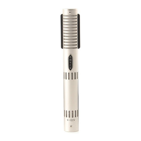
royer R-122V Operation Instructions Manual & User Manual
Vacuum tube ribbon velocity microphone
Hide thumbs
Also See for R-122V:
- Operation instructions manual & user manual (25 pages) ,
- Operation instructions manual and user manual (24 pages)

Related Manuals for royer R-122V


Summary of Contents for royer R-122V
- Page 1 ROYER Labs Model R-122V Vacuum Tube Ribbon Velocity Microphone Operation Instructions Manual & User Guide Made in U.S.A.
-
Page 2: Table Of Contents
TABLE OF CONTENTS Model R-122V Vacuum Tube Ribbon Microphone Revised August 2006 Introduction page 2 Active Ribbon Technology page 3 Description page 5 Applications page 5 Ribbons in the Digital World page 6 User Guide page 6 Power Supply Input Module... -
Page 3: Introduction
Please read this manual thoroughly in order to become familiar with all of the R-122V’s capabilities. It will assist you in making the most of your microphone’s superior acoustic properties. This operator’s manual is a handy reference guide and we suggest you refer to it whenever questions arise about the use and care of your R-122V active ribbon microphone. -
Page 4: Active Ribbon Technology
SPL handling without the use of pads. The system gives the R-122V an output level comparable to that of condenser microphones, and its buffer stage provides a low impedance output while presenting a perfect impedance load to the ribbon element. - Page 5 The R-122V also has an enormous amount of headroom available, making it useful on extremely loud applications. Phantom powered microphones are limited with regard to maximum headroom as a result of the phantom power source. With the vacuum tube design, greater headroom is achievable because the voltage source is supplied by a dedicated power supply.
-
Page 6: Description
However, ribbon microphones are somewhat more sensitive to direct blasts of air and the R-122V is no exception to this rule. Discretionary use of a windscreen or pop screen, such as the... -
Page 7: Ribbons In The Digital World
User Guide Using the R-122V vacuum tube Ribbon Microphone The head amplification system used in the R-122V consists of a sub-miniature military grade vacuum tube configured as a cathode follower. This circuit arrangement offers ideal impedance matching properties and very high headroom. The vacuum tube is powered from a dedicated power supply that supplies high voltage B+ and heater current through the microphone cable. - Page 8 R-122V’s power supply ramps up power to the microphone slowly, minimizing stress on the microphone’s electronics and extending the life of the tube. We recommend letting the R-122V warm up for at least 15 minutes prior to use. When the microphone becomes operational, bring the channel fader to 0-dB (unity) and use the trim to set the desired level.
-
Page 9: Power Supply Input Module
5. When disconnecting the microphone, bring the channel fader down, turn the R122V's power supply OFF and unplug the microphone cable from the power supply. 6. If the studio has the microphone lines brought to a patch bay (tie lines), never crosspatch a microphone line when phantom is applied or the monitor volume is raised. - Page 10 The fuses are located inside two carriers, each marked with an arrow pointing to the right. These carriers can be pulled out with the tip of a screwdriver blade or a pair of needle nose pliers (image 4). Once the carriers are removed, the fuses can be Image 3 pulled out with your fingers.
-
Page 11: Operation
There are a few important facts about ribbon microphones that are key in understanding how to use them intelligently. 1. The R-122V is a side address, bi-directional microphone and it’s rejection in the “dead” areas is very strong. Due to this directionality, the R-122 should be placed at 1.3 times the distance... -
Page 12: Amplification Considerations
4. Always provide adequate protection for your R-122V, or any ribbon microphone. If the microphone is to remain set up on a stand when not in use, place a “mic sock” (supplied with every Royer microphone) over it until it is to be used. Do not carry the microphone around without placing a mic sock over it. -
Page 13: Equalization & Ribbon Microphones
EQ. Even with substantial amounts of equalization, ribbons retain their natural, “real” quality. For example, when a lead vocal is being performed on an R-122V, you can actually boost upper-end frequencies to the point where the R-122V emulates the performance curve of a condenser mic with excellent... -
Page 14: Hum, Noise & Mic Orientation
Even an active ribbon microphone like the R-122V is not completely immune to this phenomenon. Vintage ribbon microphones often have poor shielding and the problem can be worse. The cure for this problem is to identify the source of the noise and move the microphone away from it. -
Page 15: The Sweet Spot
induced noise can effectively be eliminated in cables simply by moving the cable away from the offending source. The Sweet Spot Finding and Working with the Sweet Spot Good engineers know the importance and benefits of finding and working with the “sweet spot” of a given microphone. The sweet spot is usually defined as the optimum placement (working distance and angular position) of any microphone relative to the sound source. -
Page 16: Other Types Of Microphones
2. Frequency response variation due to treble losses as a result of absorption and “narrowing” of the pattern at high frequencies, causing weakening of highs as the microphone is moved away from the sound source. 3. Variation in ratio of direct to reverberant sound. Tendency of a microphone to favor the nearest sound source due to a combination of these items, plus the influence of the inverse square law. - Page 17 to proximity effect) can be turned to an advantage. If an instrument, such as a trumpet, is extremely close-miked and the bass is cut to restore flat response, unwanted low-frequency sounds are cut back by upwards of 20dB compared to an unequalized microphone with a flat response.
-
Page 18: Microphone Technique
Reed Instruments sound full and never edgy when captured with an R-122V. Normal working distances are about a foot or two from the instrument. Strings sound very sweet and clean when recorded with R-122Vs. -
Page 19: Recording Loud Or Plosive Sounds
If the front head has a hole cut in it, position the microphone away from the hole to avoid excessive air blasts. An R-122V used as a mono room mic, four to six feet in front of the kit and compressed, will yield a surprisingly large, full drum sound. - Page 20 harmful air currents. One way to determine if the air pressure is excessive is to place your hand in front of the sound source (the kick drum, the guitar cab, etc.) and see if you can feel actual air movement. If you feel air movement, do not put your ribbon microphone there.
- Page 21 2. Example of Horizontal PositionTechnique Angling the micro- phone slightly will minimize stressing the ribbon. Due to the microphone’s pick-up pattern, sound will not be affected 3. Side View of Kick Drum miking Technique A) Close miking - angle mic so that pressure wave iss off-axis B) Standard miking position 4.
-
Page 22: Stereophonic Microphone Technique
Stereophonic Microphone Technique Classic Blumlein Technique For many years, several “coincident” microphone setups have been widely used for picking up sounds in stereo as naturally as possible. The “Blumlein” technique, named for A.D. Blumlein of England, involves the use of two figure-eight microphones positioned as in the sketch (see Figure 1), so that one faces left and the other right, at an angle of 90º... - Page 23 Mid-Side (M-S) Technique In the early days of stereo radio broadcasting, the mid-side recording technique was developed to allow for 1) simultaneous stereo and mono feeds from the same mic array and 2) electronic manipulation of the width of the stereo image. In M-S recording, one mic faces sideways, one faces forward as shown in Figure 2, and they are connected as shown in Figure 3.
-
Page 24: Specialized Recording Techniques
An interesting phenomenon as a result of this offset ribbon construction is that the R-122V records slightly brighter on its back side than on its front (logo) side, when the microphone is three feet or closer to the sound source. -
Page 25: Care & Maintenance
Cautionary Note: It is important to note that the SPL handling capability of the rear side of the R-122V is lower than its front side. The R-122V is rated for 135dB SPL on its front side, but recordings on the rear side should not exceed 115dB SPL. - Page 26 Keep metal filings away from the microphone at all times. The R-122V’s strong magnets can attract even the smallest metal particles into the ribbon transducer, which can result in compromised performance and the need for a re-ribbon.
- Page 27 Voltage Conversion The R-122V is energized from a dedicated power supply that operates from an AC voltage source. The supply can be configured to operate with the following voltages: 100-120 Volts 50-60HZ 220-240 Volts 50-60HZ Fuse Replacement The AC line fuse is located within the IEC power connector. Your power supply was shipped with a fuse rating suitable for the country in which it was sold.
-
Page 28: Troubleshooting
Troubleshooting Most troubleshooting issues can be traced to some form of pilot error, so we'll cover the obvious first. If the microphone produces no output whatsoever, establish that the cables are properly connected and that none of the pins in the 7-pin cable-set are damaged, bent or missing. -
Page 29: Features & Specifications
Features & Specifications R-122V Features: • Very high overload characteristics – maximum SPL greater than 135dB • Vacuum tube electronics offer greatly enhanced output and constant, optimized impedance to the ribbon element • Extremely low residual noise • Ribbon element is unaffected by heat or humidity •... -
Page 30: Mechanical Specifications
Mechanical Specifications High-grade Neodymium magnet assembly in Royer’s patented Flux-Frame 1.5” x 3/16” x 2.5 micron ribbon assembly Stainless steel internal baffle and dampener Dimensions: 206 mm L x 25 mm W (8-1/8” L x 1” W) Microphone Weight: 10.2 oz, 290 g Power Supply Weight: 3.5 lbs, 1.6 Kg Shipping Weight:... -
Page 31: Polar Pattern & Frequency Response
Polar Pattern Frequency Response... -
Page 32: Notes
Notes:... -
Page 33: Warranty
To validate this warranty, product registration and proof of purchase must be on file with Royer Labs. This warranty does not apply if the product has been damaged by accident or misuse, or as a result of repair or modification by other than a Royer Labs customer service facility authorized to service this product.
Need help?
Do you have a question about the R-122V and is the answer not in the manual?
Questions and answers