Table of Contents
Advertisement
Quick Links
Advertisement
Table of Contents

Subscribe to Our Youtube Channel
Related Manuals for Icom iF110S


Summary of Contents for Icom iF110S
- Page 1 INSTRUCTION MANUAL VHF TRANSCEIVER iF110S UHF TRANSCEIVER iF210S...
-
Page 2: Important
Icom, Icom Inc. and the logo are registered trademarks of the supplied microphone only. Other microphones Icom Incorporated (Japan) in the United states, the United have different pin assignments and may damage the trans- Kingdom, Germany, France, Spain, Russia and/or other coun- ceiver. -
Page 3: Table Of Contents
I Cleaning ................. 13 4 OPTIONS ................... 14 For U.S.A. only 5 CE ....................15 CAUTION: Changes or modifications to this transceiver, not ex- pressly approved by Icom Inc., could void your authority to operate this transceiver under FCC regulations. -
Page 4: Panel Description
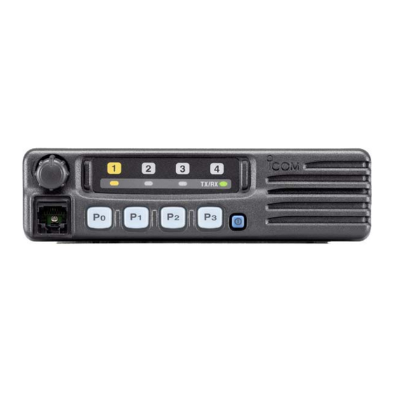
PANEL DESCRIPTION I Front panel Function LED (p. 2) TX/RX q AF VOLUME CONTROL KNOB e DEALER-PROGRAMMABLE KEYS [P0] to [P3] ➥Rotate the knob to adjust the audio output level. ➥Desired functions can be programmed independently by • Minimum audio level is pre-programmed. your Dealer. -
Page 5: I Function Led
PANEL DESCRIPTION I Function LED D D MICROPHONE ➥The supplied microphone has a PTT switch and a hanger hook. • The following functions are available when the microphone is on or off hook: - Automatic scan start when hook on. TX/RX - Automatic priority channel selection when hook off. -
Page 6: I Programmable Function Keys
The following functions can be assigned to [P0], [P1], [P2] and [P3] programmable function keys. Consult your Icom Dealer or System operator for details con- ¡ ¡ PRIORITY CHANNEL KEYS cerning your transceiver’s programming. Push these keys to select priority A or priority B... - Page 7 PANEL DESCRIPTION ¡ ¡ MONITOR KEY ¡ ¡ TALK AROUND KEY Activates one of (or two of) the following functions Turns the talk around function ON and OFF. MONI on each channel independently: • The talk around function equalizes the transmit frequency to the receive frequency for mobile-to- •...
- Page 8 PANEL DESCRIPTION ¡ ¡ EMERGENCY KEY ¡ ¡ SCRAMBLER KEY Push and hold the key to transmit an emergency call. • Push and hold to turn the voice scrambler func- EMER SCRM • If you want to cancel the emergency call, push tion ON.
-
Page 9: Operation
OPERATION I Turning power ON I Channel selection q Push [ ] to turn the power ON. Several types of channel selection are available. The meth- ods may differ according to your system setup. w If the transceiver is programmed for a start up passcode, input the digit codes as directed by your Dealer. -
Page 10: I Receiving And Transmitting
OPERATION I Receiving and transmitting IMPORTANT: To maximize the readability of your signal: (1) Pause briefly after pushing [PTT] (2) Hold the microphone 2 to 5 cm from your mouth, then RECEIVING: q Push [POWER] to turn the power ON. speak into the microphone at a normal voice level. -
Page 11: D Scrambler Function
OPERATION eThen push [P2] and [P3] to set the desired level/condition. D Scrambler function rPush [POWER] (or push and hold [P0]) again to exit set The UT-109 (#02) or UT-110 (#02) optional voice scrambler mode. unit provides high performance private communication between stations with the same scrambler codes. -
Page 12: Connection And Maintenance
CONNECTION AND MAINTENANCE I Rear panel and connection Optional speaker q Antenna (SP-22) R C A U T I O N ! N E V E R r e- red: move the fuse-holder from the DC power cable. NOTE: Use the terminals as shown below for the cable connections. -
Page 13: I Supplied Accessories
CONNECTION AND MAINTENANCE I Supplied Accessories q ANTENNA CONNECTOR Connects to an antenna. Ask your Dealer about antenna selection and placement. w MICROPHONE HANGER Connect the supplied microphone hanger to the vehicle’s KEY-STICKER ground for microphone on/off hook functions. (See p. 1) e DC POWER RECEPTACLE Connects to a 12 V DC battery. -
Page 14: I Mounting The Transceiver
CONNECTION AND MAINTENANCE I Mounting the transceiver I Optional UT-108 installation The universal mounting bracket supplied with your transceiv- Install the optional UT-108 DTMF decoder unit as follows: er allows overhead mounting. q Turn the power OFF, then disconnect the DC power cable. •... -
Page 15: I Optional Ut-109/Ut-110 Installation
CONNECTION AND MAINTENANCE I Optional UT-109 /UT-110 I Optional OPC-617 installation installation Install the OPC-617 as shown below. q Turn the power OFF, then disconnect the DC power cable. w Unscrew the 4 screws, then remove the bottom cover. e Cut the pattern on the PCB at the TX mic circuit (MIC) and RX AF circuit (DISC) as shown below. -
Page 16: I Antenna
CONNECTION AND MAINTENANCE I Antenna A key element in the performance of any communication sys- tem is an antenna. Ask your Dealer about antennas and the best places to mount them. I Fuse replacement A fuse is installed in the supplied DC power cable. If a fuse blows or the transceiver stops functioning, track down the source of the problem, if possible, and replace the damaged fuse with a new rated one. -
Page 17: Options
OPTIONS SP-22 EXTERNAL SPEAKER Compact and easy-to-install. Input impedance : 4 Ω Max. input power : 5 W HM-100TN DTMF microphone. SM-25 Desktop microphone. UT-108 DTMF DECODER UNIT Provides pager and code squelch capabilities. UT-109/UT-110 (#02) VOICE SCRAMBLER UNIT • UT-109 : Non-rolling type (max. 32 codes) •... - Page 18 About e-marking: Detailed installation notes for Icom mobile transceivers to be fitted into vehicles are available. Please contact your Icom dealer or distributor.
- Page 19 DECLARATION OF CONFORMITY We Icom Inc. Japan 0168 1-1-32, Kamiminami, Hirano-ku Osaka 547-0003, Japan Declare on our sole responsibility that this equipment complies with the essential requirements of the Radio and Telecommunications Terminal Equipment Directive, 1999/5/EC, and that any applicable Essential Test Düsseldorf 30st Jul.
- Page 20 Count on us! < Intended Country of Use > A-6200H-1EU Printed in Japan 1-1-32 Kamiminami, Hirano-ku, Osaka 547-0003 Japan © 2002 Icom Inc.
Need help?
Do you have a question about the iF110S and is the answer not in the manual?
Questions and answers