
Subscribe to Our Youtube Channel
Related Manuals for Icom iF3102D


Summary of Contents for Icom iF3102D
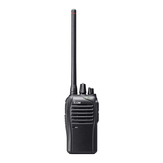
- Page 1 Limited functions only Limited functions only INSTRUCTION MANUAL VHF TRANSCEIVER iF3102D UHF TRANSCEIVER iF4102D The photo shows the VHF transceiver.
-
Page 2: Explicit Definitions
If disregarded, inconvenience only. No risk NOTE of personal injury, fire or electric shock. Icom, Icom Inc. and the Icom logo are registered trademarks of Icom Incorpo- rated (Japan) in Japan, the United States, the United Kingdom, Germany, France, Spain, Russia and/or other countries. -
Page 3: Voice Coding Technology
VOICE CODING TECHNOLOGY The AMBE+2™ voice coding Technology embodied in this product is protected by intellectual property rights including patent rights, copyrights and trade secrets of Digital Voice Systems, Inc. This voice coding Technology is licensed solely for use within this Com- munications Equipment. -
Page 4: Precautions
Use and charge only specified Icom battery packs with Icom radios or Icom chargers. Only Icom battery packs are tested and approved for use with Icom radios or charged with Icom chargers. Using third-party or counterfeit battery packs or chargers may cause smoke, fire, or cause the battery to burst. - Page 5 DO NOT modify the transceiver. The transceiver warranty does not cover any problems caused by unauthorized modification. DO NOT use harsh solvents such as benzine or alcohol when cleaning, as they will damage the transceiver surfaces. BE CAREFUL! The transceiver will become hot when operating it continuously for long periods of time.
-
Page 6: Table Of Contents
TABLE OF CONTENTS FOREWORD ..................i EXPLICIT DEFINITIONS ..............i VOICE CODING TECHNOLOGY ............ii PRECAUTIONS ................iii, iv TABLE OF CONTENTS ..............v, vi 1 ACCESSORIES ................. 1–4 ■ Supplied accessories ..............1 ■ Accessory attachments .............. 1 2 PANEL DESCRIPTION ............5–11 ■... - Page 7 ■ Position data transmission ............30 ■ Status message transmission ........... 30 ■ Encryption function ..............30 5 BATTERY CHARGING ............31–41 ■ Caution (for the BP-264 )........31 mh battery ■ Caution (for the BP-265 Li-ion ) ........33 battery ■...
-
Page 8: Accessories
ACCESSORIES ■ Supplied accessories The following accessories are supplied with the transceiver. Battery pack* Flexible antenna (This illustration is for the VHF type.) Battery charger* AC adapter* Belt clip* Jack cover (with screws) * Not supplied, or the shape is different, depending on the version. ■... - Page 9 ACCESSORIES D Belt clip To attach the belt clip: ➥ Slide the belt clip in the direction of the arrow until the belt clip locks in place, and makes a ‘click’ sound. Belt clip Battery pack To detach the belt clip: q Remove the battery pack from the transceiver, if it is attached.
- Page 10 ACCESSORIES D Battery pack or case To attach the battery pack or case: q Fit the battery pack/case in the direction of the arrow, then close w Hook the latch until it makes a ‘click’ sound. Battery pack/case Latch To remove the battery pack/case: Be careful! The latch is tightly locked, so use caution when re- leasing it.
- Page 11 ACCESSORIES NEVER remove or attach the battery pack/case when the trans- ceiver is wet or soiled. This may result in water or dust getting into the transceiver, battery pack/case, and may result in them being damaged. NOTE: Keep the battery terminals clean. It’s a good idea to clean the battery terminals once a week.
-
Page 12: Panel Description
PANEL DESCRIPTION ■ Front, top and side panels ROTARY SELECTOR VOLUME ANTENNA CONTROL CONNECTOR LED INDICATOR PTT SWITCH Speaker SPEAKER- UPPER KEY MICROPHONE LOWER KEY JACK Microphone q ROTARY SELECTOR Rotate to select the pre-programmed memory channels or scan lists, depending on the pre-programming. w VOLUME CONTROL [VOL] Rotate to turn the power ON or OFF, and adjust the audio level. - Page 13 PANEL DESCRIPTION e LED INDICATOR (p. 7) ➥ Lights red* while transmitting. * When the optional battery case is attached, the LED indicator lights orange. ➥ Lights green while receiving a signal, or when the squelch is open. ➥ Lights/blinks orange when the matched 2/5-tone code is re- ceived, depending on the pre-programming.
-
Page 14: Led Indicator
PANEL DESCRIPTION ■ LED indicator The LED indicator indicates the status of various parameters of the transceiver as follows; (Ref.; R=Red, G=Green, O=Orange) • TX: Lights Red while transmitting a signal. • RX: Lights Green while receiving a signal. • Call LED (ON): Turns ON while receiving a matched 2/5-tone. ED O N •... -
Page 15: Programmable Function Keys
■ Programmable function keys The following functions can be assigned to the [Upper] and [Lower] programmable function keys. Consult your Icom dealer or system operator for details concerning your transceiver’s programming. SCAN Push to start and cancel the scanning operation. - Page 16 PANEL DESCRIPTION MONITOR, MONITOR (AUDIBLE) ➥ Push to turn the CTCSS (DTCS) or 2/5-tone squelch Mute ON or OFF. • Only during LMR operation, push to open any squelch func- tions, or deactivate any mute functions. • Only during PMR operation, push to activate one or two of the following functions* on each channel.
- Page 17 PANEL DESCRIPTION WIDE/NARROW ➥ Push to switch the IF bandwidth to Wide. • The wide passband width can be selected from 20 or 25 kHz using the optional cloning software (PMR operation only). Ask your dealer for details. ➥ Hold down to switch the IF bandwidth to Narrow. CALL, CALL A, CALL B Push to transmit a 2/5-tone code.
- Page 18 PANEL DESCRIPTION SIREN Hold down for 1 second to emit a siren sound. This function can be used for situations other than an emergency alert, such as a security alarm for example. The transceiver emits the siren sound until the power is turned OFF.
-
Page 19: Basic Operation
BASIC OPERATION ■ Turning power ON Prior to using the transceiver for the first time, the battery pack must be fully charged for optimum life and operation. (p. 31) [VOL] ➥ Rotate [VOL] to turn power ON. D Battery type selection The battery type must be selected according to the battery pack or case when it is changed, but only the first time it is used. -
Page 20: Channel Selection
BASIC OPERATION ■ Channel selection Several types of channel selecting methods are available. They may differ, according to your system set up. To select a desired operating channel, do one of the following. • Rotate [ROTARY SELECTOR]. • Push one of memory channel keys, [MR-CH 1] to [MR-CH 4]. •... -
Page 21: Call Procedure
BASIC OPERATION ■ Call procedure When your system employs tone signalling (excluding CTCSS and DTCS), the tone call procedure may be necessary prior to voice transmission. The tone signalling that is employed in the transceiver may be a selective calling system, which allows you to call only specific station(s), and prevent unwanted stations from contacting you. -
Page 22: Receiving And Transmitting
BASIC OPERATION ■ Receiving and transmitting CAUTION: Transmitting without an antenna will damage the transceiver. See page 1 for antenna attachment. Receiving: q Rotate [VOL] to turn ON the power. w Rotate [ROTARY SELECTOR], or push one of the memory chan- nel keys, [MR-CH 1] to [MR-CH 4], to select a channel. - Page 23 BASIC OPERATION D Transmitting notes • Transmit inhibit function The transceiver has several inhibit functions, which restrict trans- mission under the following conditions: - The channel is muted. (PMR operation only) - The channel is busy. - A signal with the un-matched (or matched) CTCSS (or DTCS) tone is received.
- Page 24 BASIC OPERATION D DTMF transmission If the transceiver has [DTMF Autodial] assigned to it, the automatic DTMF transmission function is usable. ➥ Push [DTMF Autodial] to transmit the DTMF code. D Receiving a Stun, Kill and Revive command The dispatcher can send a 2/5-tone signal that will stun, kill or re- vive your transceiver.
-
Page 25: Setting The Microphone Gain
BASIC OPERATION ■ Setting the microphone gain Adjusts the microphone gain. q Rotate [VOL] to turn the trans- [ROTARY SELECTOR] ceiver power OFF. [VOL] w Set [ROTARY SELECTOR] to Channel 16. e While holding down [Upper], ro- tate [VOL] to turn ON the power and enter the microphone gain adjustment mode. -
Page 26: Setting The Squelch Level
BASIC OPERATION ■ Setting the squelch level The squelch circuit mutes the received audio signal, depending on the signal strength. q Rotate [VOL] to turn the trans- [ROTARY SELECTOR] ceiver power OFF. [VOL] w Set [ROTARY SELECTOR] to any channel other than Chan- nel 16. -
Page 27: Setting The Beep Level
BASIC OPERATION ■ Setting the Beep level The beep function can be turned ON or OFF, and its level can be adjusted between 1 and 5, or 1 (linked) and 5 (linked). When a Linked option is selected, the beep level is adjustable with [VOL]. q Rotate [VOL] to turn the trans- [ROTARY SELECTOR] ceiver power OFF. -
Page 28: Setting The Ringer Level
BASIC OPERATION ■ Setting the Ringer level The Ringer level can be adjusted between 1 and 5, or 1 (Linked) and 5 (Linked). When a Linked option is selected, the Ringer level is adjustable with [VOL]. q Rotate [VOL] to turn the trans- [ROTARY SELECTOR] ceiver power OFF. -
Page 29: Output Power Level Selection
BASIC OPERATION ■ Output power level selection If the transceiver has [High/Low] assigned to it, the transmit output power level can be selected, depending on the presetting. When the battery case is selected as the battery type, or the bat- tery voltage drops to a low power level and the LED indicator sta- tus is “Low Battery 2,”... -
Page 30: Mdc 1200 System Operation
BASIC OPERATION ■ MDC 1200 system operation The MDC 1200 signaling system enhances your transceiver’s capa- bilities. It allows PTT ID* and Emergency signaling. * When [PTT] is pushed and/or released, the transceiver transmits your station ID. D Transmitting an Emergency Call The MDC 1200 system’s Emergency feature can be accessed using the [Emergency] key. -
Page 31: Emergency Call
BASIC OPERATION ■ Emergency Call When [Emergency] is held down for the specified time period*, the emergency signal is transmitted once, or repeatedly, on the speci- fied emergency channel. A repeat emergency signal is automatically transmitted until you turn the power OFF. Depending on the pre-programmed settings, receiving a matching 5-tone code cancels the transmission. -
Page 32: Idas Operation
IDAS OPERATION ■ IDAS operation The IC-F3102D and IC-F4102D provide Icom Digital Advanced System (IDAS) that meets the 6.25 kHz emission mask require- ments for narrow banding, and increases efficiency of channel al- location and use of spectrum. NOTE: During IDAS operation, BIIS 1200 and MDC 1200 sys- tem operations are not available. -
Page 33: Receiving A Call
IDAS OPERATION ■ Receiving a call D Receiving a Call Alert q When a Call Alert is received; • The transceiver will automatically transmit the acknowledgement. • The LED indicator blinks orange. • Beeps sound. w Hold down [PTT], then speak into the microphone. e Release [PTT] to receive a response. - Page 34 IDAS OPERATION D Receiving a Remote Monitor or Radio Check Call If an individual call with Remote monitor or Radio check command is received (RAN code matching is not necessary depending on the presetting), the transceiver will automatically transmit. ➥ When a Remote monitor command is received; •...
-
Page 35: Transmitting A Call
IDAS OPERATION ■ Transmitting a call IDAS operation allows you to make a call to a specific station (In- dividual call) or to a particular group (Talkgroup call). Other digital mode transceivers on the channel will not receive a call that does not match their individual or talkgroup ID and/or RAN (Radio Ac- cess Number) code. - Page 36 IDAS OPERATION IMPORTANT: It is recommended to set an emergency channel individually to provide the certain emergency call operation. NOTE: The Digital Request Ack function is activated, the trans- ceiver transmits the emergency call with the request to send back an acknowledgment.
-
Page 37: Position Data Transmission
IDAS OPERATION ■ Position data transmission When an optional HM-171GP or any other GPS receiver is con- nected to the transceiver, the position (longitude and latitude) data can be transmitted automatically when; • After sending a Status Call - Set the ‘Send with Status Call’ item as ‘Enable.’ •... -
Page 38: Battery Charging
BATTERY CHARGING ■ Caution (for the BP-264 mh battery R DANGER! NEVER short terminals (or charging terminals) of the battery pack. Also, current may flow into nearby metal objects such as a necklace, so be careful when placing battery packs (or the transceiver) in handbags, etc. - Page 39 BATTERY CHARGING If your Ni-MH battery pack seems to have no capacity, even after being charged, completely discharge it by leaving the power ON overnight. Then, fully charge the battery pack again. If the battery pack still does not retain a charge (or only very little charge), a new battery pack must be purchased.
-
Page 40: Caution (For The Bp-265 Li-Ion Battery )
BATTERY CHARGING ■ Caution (for the BP-265 Li-ion battery Misuse of Li-ion batteries may result in the following hazards: smoke, fire, or the battery may rupture. Misuse can also cause damage to the battery or degradation of battery performance. R DANGER! NEVER short terminals (or charging terminals) of the bat- tery pack. - Page 41 R WARNING! Immediately stop using the battery if it emits an abnor- mal odor, heats up, or is discolored or deformed. If any of these condi- tions occur, contact your Icom dealer or distributor. R WARNING! NEVER use deteriorated battery packs. They could cause a fire.
- Page 42 CAUTION: DO NOT charge the battery outside of the specified temperature range: BC-193 (+10˚C to +40˚C). Icom recommends charging the battery at +20˚C. The battery may heat up or rupture if charged out of the specified temperature range. Additionally, bat-...
-
Page 43: Battery Chargers
BATTERY CHARGING ■ Battery chargers D Using the BC-191 to rapid charge the BP-264 The BC-191 provides rapid charging of the Ni-MH battery pack (BP-264 only). Never use for any other battery pack. Charging time period: Approximately 2 hours (for the BP-264) The following item is additionally required: •... - Page 44 BATTERY CHARGING D Using the BC-192 to regular charge the BP-264 The BC-192 provides regular charging of the Ni-MH battery pack (BP-264 only). Never use for any other battery pack. Charging time period (with BC-147S): Approximately 16 hours (for the BP-264) The following item is additionally required: •...
- Page 45 BATTERY CHARGING D Using the BC-193 to rapid charge the BP-265 The BC-193 provides rapid charging of the Li-ion battery pack (BP-265 only). Never use for any other battery pack. Charging time period: Approximately 2.5 hours (for the BP-265) The following item is additionally required: •...
- Page 46 BATTERY CHARGING D Using the BC-197 to rapid charge the BP-264 or BP-265 The BC-197 rapidly charges up to six battery packs. Charging time for BP-264: Approximately 2 hours Charging time for BP-265: Approximately 2.5 hours The following additional item is required: •...
- Page 47 BATTERY CHARGING There are two types of BC-197 chargers for the IC-F3102D or IC- F4102D; one is for Ni-MH batteries, and the other is for Li-ion bat- teries. Before you purchase a BC-197, check the type of battery you are using, and then be sure to choose the suitable charger.
- Page 48 BATTERY CHARGING IMPORTANT: Ensure the tabs on the battery pack are correctly aligned with the guide rails inside the charger. Tabs BC-191, BC-192, BC-193 Guide rail...
-
Page 49: Battery Case
BATTERY CASE ■ Optional battery case (BP-263) When using the optional battery case, install 6 × AA (LR6) size alkaline batteries, as illustrated below. q Remove the battery case, if it is attached. (pp. 3, 4) w Install 6 × AA (LR6) size alkaline batteries. •... -
Page 50: Options
OPTIONS D BATTERY PACK Battery pack Voltage Capacity Battery life* Battery case for BP-263 —* AA (LR6) × 6 alkaline 12 hrs. BP-264 7.2 V 1400 mAh (typ.) 11.3 hrs. 17.5 hrs. 1900 mAh (min.) BP-265 7.4 V 2000 mAh (typ.) 16.1 hrs. - Page 51 OPTIONS • BC-197 muLti charger For rapid simultaneously charging of up to six battery packs. An AC adapter may be supplied with the charger, depending on the version. There are two types of BC-197 chargers for the IC-F3102D/ IC-F4102D. BC-197 Charger Type Chargeable Battery Charging time With AD-120*...
- Page 52 Approved Icom optional equipment is designed for optimal performance when used with an Icom transceiver. Icom is not responsible for the destruction or damage to an Icom trans- ceiver in the event the Icom transceiver is used with equipment that is not manufactured or approved by Icom.
-
Page 53: Vox Function
OPTIONS ■ VOX function The transceiver has a VOX function, which allows you hands-free operation. An optional headset (HS-94/HS-95/HS-97) and a plug adapter cable (OPC-2004) are additionally required for operation. • The VOX (voice operated transmission) function starts transmitting when you speak into the microphone, without needing to push the PTT switch;... - Page 54 OPTIONS D Turning the VOX function ON or OFF The VOX function can be turned ON or OFF when turning the trans- ceiver power ON. q Rotate [VOL] to turn the trans- [ROTARY SELECTOR] ceiver power OFF. [VOL] w Set [ROTARY SELECTOR] to any channel other than Chan- nel 16.
- Page 55 OPTIONS D Setting the VOX gain The VOX sensitivity level can be adjusted from 1 (minimum) to 10 (maximum). [ROTARY SELECTOR] Connect the optional headset [VOL] (HS-94, HS-95 or HS-97) OPC-2004. (p. 46) urn the trans- w Rotate [VOL] to t ceiver power OFF.
- Page 56 MEMO...
- Page 57 MEMO...
- Page 58 MEMO...
- Page 59 MEMO...
- Page 60 A6891D-1EU-1a Printed in Japan © 2011–2018 Icom Inc. 1-1-32 Kamiminami, Hirano-ku, Osaka 547-0003, Japan Printed on recycled paper with soy ink.
Need help?
Do you have a question about the iF3102D and is the answer not in the manual?
Questions and answers