Table of Contents
Advertisement
Advertisement
Table of Contents

Related Manuals for OEM IPX7A-ION

Summary of Contents for OEM IPX7A-ION
- Page 1 IPX7A-ION Motherboard Reference Guide...
-
Page 2: Table Of Contents
Removing a SO-DIMM ............... 11 5 Expansion slot ..................12 Installing an expansion card ............12 6 Selectors ....................13 7 Connectors ................... 14 8 BIOS Setup reference ................20 Main ....................20 Advanced ...................21 Power ..................24 Boot ....................28 Exit .....................30 IPX7A-ION Motherboard Reference Guide... -
Page 3: Notices
This digital apparatus does not exceed the Class B limits for radio noise emissions from digital apparatus set out in the Radio Interference Regulations of the Cana- dian Department of Communications. This class B digital apparatus complies with Canadian ICES-003. IPX7A-ION Motherboard Reference Guide... -
Page 4: Safety Information
IMPORTANT: This symbol of the crossed out wheeled bin indicates that the product (electrical and electronic equipment) should not be placed in mu- nicipal waste. Check local regulations for disposal of electronic products. IPX7A-ION Motherboard Reference Guide... -
Page 5: Specifications Summary
1x Front panel audio connector 1x COM port connector 1x CD in connector 1x ROM recovery connector 1x Front panel connector 2x USB connectors BIOS SPI 8Mb (AMI) Form factor mini-ITX (170 mm x 170 mm) IPX7A-ION Motherboard Reference Guide... - Page 6 IPX7A-ION Motherboard Reference Guide...
-
Page 7: Hardware Installation
Hardware Installation This manual provides descriptions of each component on the motherboard and how to setup necessary items. IPX7A-ION Motherboard Reference Guide... -
Page 8: Before You Proceed
Failure to do so can cause you physical injury and damage motherboard components. Package contents Check your package for the following items. • Motherboard • Cables • Accessories • Drivers & Utilities Support Disc • This Motherboad Reference Guide IPX7A-ION Motherboard Reference Guide... -
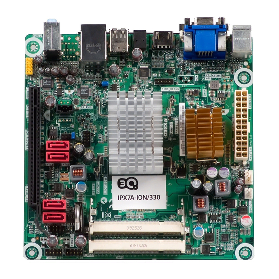
Page 9: Motherboard Layout
Rear panel connectors Display Mouse Display (RJ-45) port (PS/2) port (D-SUB) port (HDMI) port Blue: Line In Lime: Front-L/R out Pink: Mic In Display SPDIF USB 2.0 Keyboard (PS/2) port (DVI-I) port output port ports IPX7A-ION Motherboard Reference Guide... -
Page 10: System Memory
A* : Supports one module inserted in any slot as Single-channel memory con- figuration. B* : Supports one pair of modules inserted into either the blue slots or the black slots as one pair of Dual-channel memory configuration. IPX7A-ION Motherboard Reference Guide... -
Page 11: Installing A So-Dimm
2. Remove the SO-DIMM from the socket. (This is only an example.) TIP: Support the SO-DIMM lightly with your fingers when pressing the re- taining clips. The SO-DIMM might get damaged when it flips out with extra force. IPX7A-ION Motherboard Reference Guide... -
Page 12: Expansion Slot
4. Align the card connector with the slot and press firmly until the card is com- pletely seated on the slot. 5. Secure the card to the chassis with the screw you removed earlier. 6. Replace the system cover. IPX7A-ION Motherboard Reference Guide... -
Page 13: Selectors
3. Turn ON the computer to POST screen. 4. Turn OFF the computer. 5. Move the cap back to Default. 6. Enter BIOS setup to verify or configure new settings. CMOS+PW (Default) Clear CMOS and password IPX7A-ION Motherboard Reference Guide... -
Page 14: Connectors
+12V and that the PSU has a minimum power rating of 350 W. The system may become unstable or may not boot up if the power is inadequate. NOTE: You must install a PSU with a higher power rating if you intend to install additional devices. ATXPOWER IPX7A-ION Motherboard Reference Guide... -
Page 15: System Fan Connectors
SYS_ FAN2 SYS_ FAN1 Serial ATA connectors These connectors are for the Serial ATA signal cables for Serial ATA devices. SATA0 SATA1 SATA2 SATA3 Ground SATA_TX(+) SATA_TX(-) Ground SATA_RX(-) SATA_RX(+) Ground IPX7A-ION Motherboard Reference Guide... -
Page 16: Front Panel Audio Connector
These USB connectors comply with USB 2.0 specifications which support up to 480 Mbps connection speed. WARNING: Never connect a 1394 cable to the USB connectors. Doing so will damage the motherboard! F_USB2 F_USB1 USB*(-) USB*(-) USB*(+) USB*(+) Ground Ground IPX7A-ION Motherboard Reference Guide... -
Page 17: Internal Serial Port Connector
COM1 ROM recovery connector This connector allows qualified technicians to reload firmware into the SPI boot flash in case there is problem with the data. ROM RECOVERY SPI_CS# SPI_CS# SPI_MOSI 3VSB SPI_MISO Ground SPI_CLK IPX7A-ION Motherboard Reference Guide... - Page 18 This connector allows you to receive stereo audio input from sound sources such as an optical disc drive, a TV tuner, or a specialized audio/sound-processing card. CD IN Right Audio Channel Ground Ground Left Audio Channel IPX7A-ION Motherboard Reference Guide...
- Page 19 Pressing the power switch for more than four seconds while the system is ON turns the system OFF. Reset button (2-pin RESET) This 2-pin connector is for the chassis-mounted reset button for system reboot without turning off the system power. IPX7A-ION Motherboard Reference Guide...
-
Page 20: Bios Setup Reference
Displays the auto-detected BIOS information. System Memory Displays the auto-detected system memory information. System Time [xx:xx:xx] This item allows you to set the system time. System Date [Day xx/xx/xxxx] This item allows you to set the system date. IPX7A-ION Motherboard Reference Guide... -
Page 21: Advanced
1st, 2nd, 3rd, 4th Drive While entering Setup, the BIOS automatically detects the presence of SATA devices. There is a separate sub-menu for each SATA device. Select a device item then press <Enter> to display the SATA device information. IPX7A-ION Motherboard Reference Guide... -
Page 22: Usb Configuration
This item shows how fast your system fan is running. The fields for unconnected connectors will read “N/A”. Display field only: [xxxx RPM] System Fan1/Fan2 Check This item alllows your system to detect if the fan is faulty. Default: [Disabled] / Options: [Disabled] [Enabled] IPX7A-ION Motherboard Reference Guide... -
Page 23: Onboard Device Configuration
This item allows you to enable or disable the Onboard LAN settings. Default: [Enabled] / Options: [Disabled] [Enabled] PXE rom boot support This item allows you to enable or disable PXE rom boot support. Default: [Disabled] / Options: [Disabled] [Enabled] IPX7A-ION Motherboard Reference Guide... -
Page 24: Power
This item allows you to enable or disable Power On By PME#. Default: [Disabled] / Options: [Disabled] [Enabled] Resume On By RTC Alarm This item allows you to enable or disable Resume On RTC Alarm. Default: [Disabled] / Options: [Disabled] [Enabled] IPX7A-ION Motherboard Reference Guide... - Page 25 This item allows you to enable or disable Power On By Ring. Default: [Disabled] / Options: [Disabled] [Enabled] EUP Mode This item allows you to enable or disable the EUP mode. Default: [Enabled] / Options: [Disabled] [Enabled] IPX7A-ION Motherboard Reference Guide...
-
Page 26: Change Supervisor Password
Password then press <Enter>. The message “Password Uninstalled” appears. NOTE: If you forget your BIOS password, you can clear it by erasing the CMOS Real Time Clock (RTC) RAM. See your hardware documentation for information on how to erase the RTC RAM. IPX7A-ION Motherboard Reference Guide... - Page 27 When set to [Always], BIOS checks for user password both when accessing Setup and booting the system. Default: [Setup] / Options: [Setup] [Always] Boot Sector Virus Protection This item allows you to enable or disable the Boot Sector Virus Protection. Default: [Disabled] / Options: [Disabled] [Enabled] IPX7A-ION Motherboard Reference Guide...
-
Page 28: Boot
Bootup Num-Lock This item allows you to select the power-on state for the NumLock. Default: [On] / Options: [Off] [On] PS2/Mouse Support This item allows you to select the PS2/Mouse setting. Default: [Auto] / Options: [Auto] IPX7A-ION Motherboard Reference Guide... - Page 29 This item allows you to enable or disable the “Keyboard Error” message during bootup. Default: [Disabled] / Options: [Disabled] [Enabled] Hit ‘DEL’ Message Display This item allows you to enable or disable the “Press DEL to run Setup” message during bootup. Default: [Enabled] / Options: [Disabled] [Enabled] IPX7A-ION Motherboard Reference Guide...
-
Page 30: Exit
Select this option only if you do not want to save the changes that you made to the Setup program. If you made changes to fields other than System Date, System Time, and Password, the BIOS asks for a confirmation before exiting. IPX7A-ION Motherboard Reference Guide... - Page 31 BIOS fields to their “low performance” settings to troubleshoot BIOS setting problems. When you select this option, a con- firmation window appears. Select Y to load defaults. Make sure you save changes before exiting. IPX7A-ION Motherboard Reference Guide...
- Page 32 IPX7A-ION Motherboard Reference Guide...
Need help?
Do you have a question about the IPX7A-ION and is the answer not in the manual?
Questions and answers