Extech Instruments Extech 470 User Manual
True rms multimeter plus ir thermometer
Hide thumbs
Also See for Extech 470:
- User manual (23 pages) ,
- User manual (17 pages) ,
- User manual (17 pages)
Table of Contents
Advertisement
Quick Links
Download this manual
See also:
User Manual
User's Guide
True RMS Multimeter
plus IR Thermometer
Extech 470
Patent Pending
Test Equipment Depot - 800.517.8431 - 99 Washington Street Melrose, MA 02176
FAX 781.665.0780 - TestEquipmentDepot.com
Visit us at www.TestEquipmentDepot.com
Back to the Extech EX470 Product Info Page
99 Washington Street
Melrose, MA 02176
Phone 781-665-1400
Toll Free 1-800-517-8431
Advertisement
Table of Contents

Related Manuals for Extech Instruments Extech 470


Summary of Contents for Extech Instruments Extech 470
- Page 1 99 Washington Street Melrose, MA 02176 Phone 781-665-1400 Toll Free 1-800-517-8431 Visit us at www.TestEquipmentDepot.com Back to the Extech EX470 Product Info Page User's Guide True RMS Multimeter plus IR Thermometer Extech 470 Patent Pending Test Equipment Depot - 800.517.8431 - 99 Washington Street Melrose, MA 02176 FAX 781.665.0780 - TestEquipmentDepot.com...
- Page 2 Introduction Congratulations on your purchase of the Extech 470 (part number EX470) True RMS Autoranging Multimeter plus IR Thermometer. This meter measures AC/DC Voltage, AC/DC Current, Resistance, Capacitance, Frequency, Duty Cycle, Diode Test, and Continuity plus Thermocouple and Non-Contact IR Temperature. Proper use and care of this meter will provide many years of reliable service.
-
Page 3: Overvoltage Category
OVERVOLTAGE CATEGORY III This meter meets the IEC 610-1-95 standard for OVERVOLTAGE CATEGORY III. Cat III meters are protected against overvoltage transients in fixed installation at the distribution level. Examples include switches in the fixed installation and some equipment for industrial use with permanent connection to the fixed installation. -
Page 4: Symbols And Annunciators
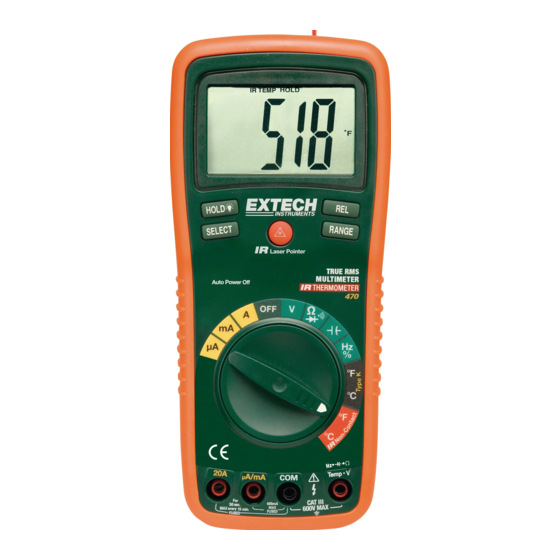
Controls and Jacks 1. IR Thermometer and laser pointer 2. 4000 count LCD display 3. HOLD and Backlight button 4. SELECT button 5. Function switch 6. mA, uA and A input jacks 7. COM input jack 8. Positive input jack 9. - Page 5 Specifications Function Range Resolution Accuracy 400mV 0.1mV ±(0.3% reading + 2 digits) Voltage 0.001V ±(0.5% reading + 2 digits) 0.01V 400V 0.1V 1000V ±(0.8% reading + 3 digits) 50 to 400Hz 400Hz to 1kHz Voltage 400mV 0.1mV ±(1.5% reading ±(2.5% reading + 15 digits) + 15digits) 0.001V...
- Page 6 Function Range Resolution Accuracy Resistance ±(0.8% reading + 4 digits) 400Ω 0.1Ω ±(0.8% reading + 2 digits) 4kΩ 0.001kΩ 40kΩ 0.01kΩ ±(1.0% reading + 2 digits) 400kΩ 0.1kΩ 4MΩ 0.001MΩ ±(3.0% reading + 5 digits) 40MΩ 0.01MΩ ±(5.0% reading + 7 digits) Capacitance 40nF 0.01nF...
- Page 7 Diode Test Test current of 0.3mA maximum, open circuit voltage 1.5V DC typical Continuity Check Audible signal will sound if the resistance is less than 150Ω (approx.), test current <0.7mA Temperature Sensor Requires type K thermocouple IR Spectral response 6 to 16µm IR Emissivity 0.95 fixed IR distance ratio...
-
Page 8: Dc Voltage Measurements
Operating Instructions WARNING: Risk of electrocution. High-voltage circuits, both AC and DC, are very dangerous and should be measured with great care. 1. ALWAYS turn the function switch to the OFF position when the meter is not in use. 2. If “OL” appears in the display during a measurement, the value exceeds the range you have selected. -
Page 9: Ac Voltage Measurements
AC VOLTAGE MEASUREMENTS WARNING: Risk of Electrocution. The probe tips may not be long enough to contact the live parts inside some 240V outlets for appliances because the contacts are recessed deep in the outlets. As a result, the reading may show 0 volts when the outlet actually has voltage on it. -
Page 10: Dc Current Measurements
DC CURRENT MEASUREMENTS CAUTION: Do not make current measurements on the 20A scale for longer than 30 seconds. Exceeding 30 seconds may cause damage to the meter and/or the test leads. 1. Insert the black test lead banana plug into the negative COM jack. -
Page 11: Ac Current Measurements
AC CURRENT MEASUREMENTS CAUTION: Do not make current measurements on the 20A scale for longer than 30 seconds. Exceeding 30 seconds may cause damage to the meter and/or the test leads. 1. Insert the black test lead banana plug into the negative COM jack. -
Page 12: Resistance Measurements
RESISTANCE MEASUREMENTS WARNING: To avoid electric shock, disconnect power to the unit under test and discharge all capacitors before taking any resistance measurements. Remove the batteries and unplug the line cords. 1. Set the function switch to the green Ω position. -
Page 13: Continuity Check
CONTINUITY CHECK WARNING: To avoid electric shock, never measure continuity on circuits or wires that have voltage on them. 1. Set the function switch to the green Ω position. 2. Insert the black lead banana plug into the negative COM jack. Insert the red test lead banana plug into the positive Ω... - Page 14 CONTACT TEMPERATURE MEASUREMENTS 1. Set the function switch to the black Type K ºF or ºC position. 2. Insert the Temperature Probe into the input jacks, making sure to observe the correct polarity. 3. Touch the Temperature Probe head to the part whose temperature you wish to measure.
- Page 15 NON-CONTACT TEMPERATURE MEASUREMENTS 1. Set the function switch to the red IR Non-Contact ºF or ºC position. 2. Point the meter at the surface to be measured. 3. If needed, press the red IR Laser Pointer button to locate the exact spot being measured.
-
Page 16: Capacitance Measurements
CAPACITANCE MEASUREMENTS WARNING: To avoid electric shock, disconnect power to the unit under test and discharge all capacitors before taking any capacitance measurements. Remove the batteries and unplug the line cords. 1. Set the rotary function switch to the green position. -
Page 17: Autoranging/Manual Range Selection
AUTORANGING/MANUAL RANGE SELECTION When the meter is first turned on, it automatically goes into AutoRanging. This automatically selects the best range for the measurements being made and is generally the best mode for most measurements. For measurement situations requiring that a range be manually selected, perform the following: Press the RANGE key. -
Page 18: Display Backlight
DISPLAY BACKLIGHT Press and hold the HOLD key for >1 second to turn on or off the display backlight function. The backlight will automatically turn off after 30 seconds. Note: The HOLD feature will activate when the Backlight is turned on. Press the HOLD key again to exit Hold. HOLD The hold function freezes the reading in the display. -
Page 19: Maintenance
Maintenance WARNING: To avoid electric shock, disconnect the test leads from any source of voltage before removing the back cover or the battery or fuse covers. WARNING: To avoid electric shock, do not operate your meter until the battery and fuse covers are in place and fastened securely. -
Page 20: Battery Installation
BATTERY INSTALLATION WARNING: To avoid electric shock, disconnect the test leads from any source of voltage before removing the battery cover. 1. Turn power off and disconnect the test leads from the meter. 2. Open the rear battery cover by removing two screws (B) using a Phillips head screwdriver. -
Page 21: Replacing The Fuses
REPLACING THE FUSES WARNING: To avoid electric shock, disconnect the test leads from any source of voltage before removing the fuse cover. 1. Disconnect the test leads from the meter. 2. Remove the protective rubber holster. 3. Remove the battery cover (two “B” screws) and the battery. 4.
Need help?
Do you have a question about the Extech 470 and is the answer not in the manual?
Questions and answers