Advertisement
Quick Links
Advertisement

Related Manuals for International Thermal Research CO32D


Summary of Contents for International Thermal Research CO32D
-
Page 1: Heating System
HEATING SYSTEM OPERATOR'S MANUAL HURRICANE is a registered trademark of International Thermal Research Ltd. Covered by U.S. Patent # 5,391,075 And other U.S. and foreign patents and patent applications Copyright 2000, 2001, 2002, 2003 International Thermal Research Ltd. -
Page 2: Table Of Contents
INDEX PAGE INTRODUCTION & TECHNICAL SPECIFICATIONS FEATURES COMPONENTS COMPONENTS OPTIONS AND ACCESSORIES INSTALLATION OVERVIEW MOUNTING THE HEATER LOCATION / ELEVATION REQUIREMENTS EXHAUST SYSTEM EXHAUST INSULATION EXHAUST MUFFLER THRU-HULL FITTINGS AIR INTAKE TUBING FUEL SYSTEM 3.10 AIR ACCUMULATOR 3.11 FAN HEATERS 3.12 BASEBOARD, TUBE &... - Page 3 VOLTAGE LOW OR HIGH OVERHEAT 5.10 FUSE BLOWN 5.11 FUEL PUMP/SOLENOID 5.12 IGNITOR 5.13 COMBUSTION FAN 5.14 WATER PUMP 5.15 FLAME OUT 5.16 COMPRESSOR 5.17 BYPASS MODE 5.18 WATER PUMP ON (GREEN) 5.19 REMOTE PANEL 5.20 LCD READOUT REMOTE PANEL (OPTIONAL) 5.21 FLAME SENSOR MODULE 5.22...
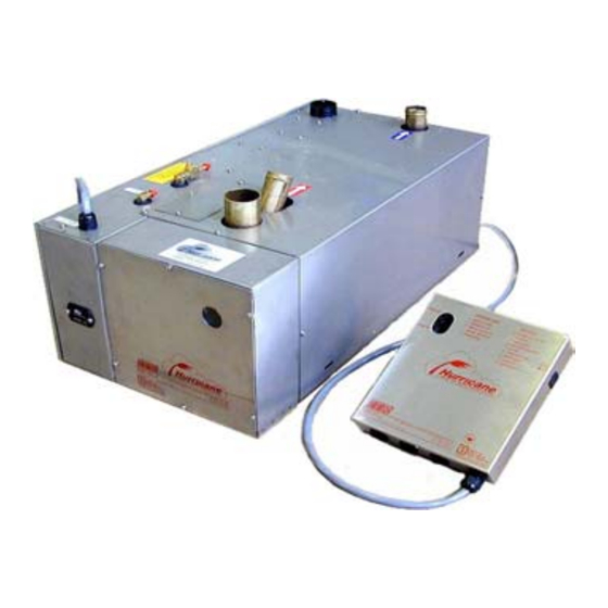
- Page 4 THE LATEST TECHNOLOGY IN A DIESEL HOT WATER HEATING SYSTEM HURRICANE The HURRICANE heater is constructed of a stainless steel case which houses all the working components. The water jacket is made of copper and brass for efficient heat transfer and brazed together for durability and long life.
- Page 5 IMPORTANT NOTICE The Hurricane heater now has an additional secondary safety shut off feature. A high temperature, overheat aquastat as shown in the pictures below. This aquastat is a manual reset only type, and if tripped, should not be reset until an authorized ITR dealer or service representative has examined the heater.
-
Page 6: Introduction & Technical Specifications
MODEL BTUH WATER EXHAUST US GAL AMPS FUEL O.D. Input Connection Outlet Capacity GAL/H FLOW h x w x d (Wt - lbs) CO32D 32,000 0.75" 1.50” 0.20 7”x11"x19.0" 45,000 0.30 CO45D (37) CO65D 65,000 0.75" or 2.0" 1.25 0.45 10"x15"x29.0"... -
Page 7: Features
FEATURES Designed for the marine and RV environment, the HURRICANE heater features unique, state of the art technology. Special features of the HURRICANE heater include: • Fuel efficient burner which burns all grades of diesel fuel, stove oil, furnace oil, and kerosene without any burner adjustments (not for use with gasoline) •... -
Page 8: Components
CHAPTER 2 COMPONENTS Below is a description of the parts that come with the basic ITR HURRICANE heater. Before you start the installation, make sure you have all of the components and ARE FAMILIAR WITH ALL ASPECTS OF THIS MANUAL. •... -
Page 9: Options And Accessories
OPTIONS AND ACCESSORIES HURRICANE options and accessories are available from selected ITR Dealers and Service Centres. Call ITR for an authorized dealer near you. • WATER PUMP - These pumps circulates water through the system. It must be sized to a flow rate and head capacity. - Page 10 • COPPER MANIFOLDS For larger installations, 2 or 3 loops are used to reduce the resistance of water flow and to distribute heat more evenly in each zone. See 3.21, circulating water pump, page 3-9. • BASEBOARD / FIN AND TUBE •...
- Page 11 • FAN HEATER – Constructed of a copper core and stainless steel enclosure, these heaters provide up to 10,000 Btuh (2.9kW) of hot air. The Cabin and Spacesaver Heaters produces up to 140 cfm. and draws a minimal amount of current (.9 amps). The fan can be cycled thermostatically to allow regulation of the amount of heat delivered to a particular area.
- Page 12 • THERMOSTAT – The HURRICANE heater can be controlled by up to four thermostats. They have a range of 50°F to 90°F with an OFF position. • ZONE CONTROL BOARD – gives you the option of running an additional 4 thermostatically controlled zones for fan heaters up to 10 amps maximum (part # 2014).
- Page 13 • EXHAUST MUFFLER – Constructed of stainless steel and packed with ceramic insulation. The straight through design eliminates any backpressure and reduces exhaust noise by up to 50% (part # 13008 - 1 ½”, 13009 - 2”). Also available in cold rolled steel. (part # 13006). •...
- Page 14 Figure 2-1 Component Parts - CO Model See Chapter 8 for complete Parts Listing...
-
Page 15: Figure 2-2: Typical Installation
Figure 2-2 Typical Installation... -
Page 16: Installation
CHAPTER 3 INSTALLATION OVERVIEW Installation of the HURRICANE heater is best done with some mechanical aptitude and electrical knowledge. It is a central hot water heating system, similar to what you might have in your home. Critical factors include sizing of the circulating pump, routing of the water lines, purging of water and fuel lines and installation of the electronic control box, among others. -
Page 17: Location / Elevation Requirements
LOCATION/ELEVATION REQUIREMENTS When planning space requirements for the HURRICANE system, remember: The expansion tank must be the highest elevation point in the system so that air can be easily expelled and water can flow directly down to the water pump. Mount the heater and all other parts of the system at a lower point than the expansion tank. -
Page 18: Exhaust Insulation
EXHAUST INSULATION If you wish to insulate the exhaust system, ask a qualified dealer for your options. Various high temperature insulation materials are available. If you do not insulate, an exhaust sleeve, can be used to protect yourself from burns due to accidental contact with the exhaust pipe (part # 5135, 5136). -
Page 19: Fuel System
FUEL SYSTEM NEVER use gasoline in your HURRICANE heater. The HURRICANE heater is designed to run on all grades of diesel fuel, furnace oil, stove oil, or kerosene. Do not install the HURRICANE heater in the same compartment where either gasoline is stored or gasoline equipment operates. Fuel connections are on the top of the heater and consist of a supply and a bleeder valve located at the top of the air accumulator. -
Page 20: Fan Heaters
3.11 FAN HEATERS Where space is limited and for individual cabin or area control, use ITR fan heaters, Cabin Heater, #6002 or Spacesaver, # 6034. These heaters draw as little as 0.9 amps and deliver 140 cfm. They should be mounted as close to the floor as possible. They have a built in aquastat, which turns on the fan when the water running through it reaches 120°F (49°C), to prevent the blowing of cold air. -
Page 21: Electrical System
3.13 ELECTRICAL SYSTEM Your HURRICANE heater and electronic control board are tested and operated together before shipping. Refer to figure 3-1, page 3-7, to see how the system is pre-wired. The small remote panel contains a LED digital diagnostic display and signal horn, allows you to turn the heater on and off remotely, and to reset the heater if a fault occurs. - Page 22 DIAGNOSTIC CODES VOLTAGE (HIGH OR LOW) 1 OVERHEAT FUSE BLOWN FUEL PUMP / SOLENOID IGNITOR COMBUSTION FAN CIRCULATING PUMP FLAME OUT COMPRESSOR HEATER CYCLING THERMOSTAT OFF REMOTE SWITCH OFF SERVICE SWITCH (OFF) BYPASS MODE TEST POINTS FLAME SENSOR (0.0 VDC TO 3.0 VDC WHILE RUNNING) OPEN COMBUSTION FAN (5.0 VDC IF OK) COMBUSTION FAN CURRENT (0.7 VDC TO 5.0 VDC IF OK) 5.0 VDC POWER SUPPLY...
-
Page 23: Remote Panel
3.16 REMOTE PANEL The remote panel controls the heater’s operation. It has a combination ON / OFF - RESET switch, a LED digital diagnostic display and 10 second signal horn, which indicates system faults or shut-down. Check the diagnostic codes for the reason. By turning the switch OFF, then ON again, it resets the fault. -
Page 24: Mounting The Expansion Tank
3.20 MOUNTING THE EXPANSION TANK Refer to Fig. 2-2, page 2-6, to see how water flows in and out of the heater. The flow directions are properly labeled in this figure, so do not reverse them during installation. 1. Mount either the horizontal or vertical expansion tank at the high point of the system and pipe to the inlet of the circulation pump. -
Page 25: Rubber Hose
3.22 RUBBER HOSE Most heating specialists now install rubber hose for the heating systems. When properly selected and installed, rubber hose provides years of service with little or no maintenance. The insulation provided by rubber hose also helps to control heat loss. If slip- on foam insulation coverings are used, even less heat will be lost. -
Page 26: Water Filling Procedure
3.25 WATER FILLING PROCEDURE After your system has been completely installed, filled with straight water, purged of all air, and operating for a period of time at normal operating temperatures, you should now double check all connections for leaks. If no leaks are found, the system can be drained and filled with a 50/50 mixture of antifreeze and water. -
Page 27: Checking Water Circulation
3.26 CHECKING WATER CIRCULATION When the system has been purged of all air, water in the expansion tank should properly circulate and the pump should run smoothly and quietly. To determine whether water is circulating properly; 1. Listen for cavitations or a bubbling sound from the pump. This means that air is left in the system and circulation is poor. -
Page 28: Figure 3-2: Optional Domestic Water Hookup
PRECAUTION: Where there is a chance of contamination of your domestic water when using a heating system, use antifreeze specifically intended for hydronic heating systems. Inhibited propylene glycol is recommended. Do not use automotive, ethylene glycol, or any undiluted or petroleum based antifreeze as they can cause severe personal injury should antifreeze leak into your potable water supply. -
Page 29: Operation
CHAPTER 4 OPERATION The initial start of your HURRICANE heater must be done by an authorized service person. Be sure that all components have been properly installed according to the instructions laid out in this manual before the initial start. STARTING THE HEATER The major steps in starting the heater are as follows: 1. -
Page 30: Main Control Board Operation
independently by the engine heat aquastat (A-A). After the heater has been running for a little while, the water outlet of the heater case should become warm. If the water hose leaving the outlet of the heater does not warm up immediately after the pump comes on, water is not circulating properly and air may be in the system. -
Page 31: Heat Exchanger Operation
HEAT EXCHANGER OPERATION If you’ve installed a heat exchanger to pre-heat your engine and recycle waste engine heat, follow these procedures. To pre-heat your engine: Turn on the heater by a manual switch or timer wired to jumper the W-W terminal. If the heat exchanger is mounted upright, close to and near the bottom of the engine, it will transfer heat to the engine’s cooling system through gravity circulation. -
Page 32: Electrical Noise
ELECTRICAL NOISE Noise is unwanted electrical signals, which produce undesirable effects in the electronic circuits of the control system and we must be aware of techniques to minimize the electrical noise on these controllers. The majority of problems stem from crude wiring practices and techniques which allow "coupling" or the transfer of electrical noise into the control circuit from the noise source. -
Page 33: Troubleshooting
CHAPTER 5 TROUBLESHOOTING OVERVIEW The electronic board consists of a flash micro controller programmed to monitor the timing and safety function of the heater. Each time the board is energized by a call for heat, it will check its own circuits for any problems. Should a problem exist, the board will shut down. -
Page 34: Remote Switch Off
- REMOTE SWITCH OFF The remote panel is switched OFF. -The burner will shut down. -The diagnostic code, will be displayed. -The control board will purge the system with the combustion fan and circulating pump for two minutes. If the remote switch is put in the ON position, the control board will resume operation and a small red LED will glow near the lower right hand corner of the digit. -
Page 35: Voltage Low Or High
- VOLTAGE LOW OR HIGH The battery or power supply voltage is below 10.5Vdc or above 15.5Vdc -The burner will shut down. -The diagnostic code, 0 will be displayed. -The buzzer will sound for 10 seconds. -The control board will purge the system with the combustion fan and circulating pump for two minutes while it is checking if the voltage fault is still present. -
Page 36: Fuel Pump/Solenoid
5.11 - FUEL PUMP/SOLENOID The fuel pump or fuel solenoid has shorted. -The burner will shut down. -The diagnostic code, 3 will be displayed. -The buzzer will sound for 10 seconds. -The control board will purge the system with the combustion fan and circulating pump for two minutes. -
Page 37: Water Pump
5.14 - WATER PUMP The water pump is shorted. -The burner will shut down. -The diagnostic code, 6 will be displayed. -The buzzer will sound for 10 seconds. -The control board will purge with the combustion fan for two minutes. -In order to restart the burner, check the water pump. -
Page 38: Compressor
5.16 - COMPRESSOR The air compressor has shorted. -The burner will shut down. -The diagnostic code, 8 will be displayed. -The buzzer will sound for 10 seconds. -The control board will purge the system with the combustion fan and circulating pump for two minutes. -
Page 39: Flame Sensor Module
5.21 FLAME SENSOR MODULE The Flame Sensor consists of a sealed module with a photodiode aimed at the flame, a red LED indicator light and 3 wires, white (+), black (-), and green (signal) connected to the main board. Under normal operating conditions whenever the burner ignition begins, the red LED will flash once indicating the white and black wires are connected and the module is receiving power and working properly. -
Page 40: A Silent Killer
5.24 A SILENT KILLER The American Boat and Yacht Council Inc. (ABYC) states: Section 5.111: "Where heater is installed in an engine or bilge space, 100% fresh air shall be supplied for combustion. Section 6.1: "Burners shall be of the mechanical draft type which employs a power driven fan, blower or other mechanism supplying air for combustion."... -
Page 41: Maintenance
CHAPTER 6 MAINTENANCE THE FIRST FEW WEEKS Once your HURRICANE heater has been installed to approved standards and workmanship, and you have test operated it a few times, your HURRICANE heater requires little maintenance. About two weeks after your HURRICANE heater has been running, you should conduct a general inspection of the entire system. -
Page 42: Nozzle
NOZZLE Nozzle problems such as clogging will result in a poor flame, small and blue. Carefully disassemble. Hold nozzle and turn stem counter clockwise. Clean distributor orifice and air slots of any debris using solvent and high pressure air. Check O-rings for nicks and replace if in doubt. A leaking O-ring will allow air into the fuel causing popping of the flame. -
Page 43: Recommended Spare Parts
RECOMMENDED SPARE PARTS Like any piece of machinery, your HURICANE heater will need servicing from time to time. A suggested maintenance schedule, page 6-4, lists suggested maintenance items and intervals. The following is a list of parts recommended to have on hand. Description Part No. - Page 44 6.10 PROTECTING HYDRONIC HEATING SYSTEMS The advantage of closed hydronic heating systems is that as long as there are no leaks, (i.e., no need for constant make-up water), the fill neutralizes (that is, it reaches equilibrium). The long term result is minimal scale build-up and insignificant corrosion since after operating for a period of time, most oxygen has been "starved"...
-
Page 45: Warranty And Service
CHAPTER 7 WARRANTY AND SERVICE WARRANTY Warranty cards must be filled in completely, signed by the Owner and Dealer and returned to ITR within 30 days of the date of the original installation. This warranty is not transferable by the owner. ITR warrants the HURRICANE water jacket to be free of defects in materials and workmanship under design usage and service conditions for three (3) years from the date of the completion of the installation or three thousand (3,000) hours of operation, whichever comes first. -
Page 46: Owner's Responsibilities
The stated express warranties are in lieu of all liabilities or obligations for damages arising out of or in connection with the delivery, use, performance, or licensing of the product or in connection with any services performed. In no event whatsoever, shall ITR be liable for indirect, consequential, exemplary, incidental, special or similar damages including but not limited to lost profits, lost business revenue, failure to realize expected savings, other commercial or economic loss of any kind or any claim against ITR by any other party arising out of or in connection with... -
Page 47: Customer Service Calls
• Diagnosis or repairs when caused by problems not directly related to the Heater or due to empty fuel tanks or poor fuel quality, fuel additives, acidic water, and electrolysis. • Running the system dry or without appropriate preservatives (antifreeze), causing damage to the heat exchanger, pump seals, etc. -
Page 48: Telephone Service
TELEPHONE SERVICE There is no charge for help or service information given over the telephone or by fax. Any recommendation or advice from ITR or any of its employees, or Dealers, is given only in good faith as an accommodation to the customer. Such information should not be relied upon by the customer without an independent verification of its applicability to the customer’s particular situation. -
Page 49: Parts
PARTS LISTING ITEM PART# DESCRIPTION ITEM PART# DESCRIPTION 9022 BURNER BOX CO 20,32,45 2020 BOLT 9104 BURNER BOX CO 65,85,105 23004 WASHER 9072 MECHANICAL BOX, CO 20,32,45 23007 WASHER 9106 MECHANICAL BOX, CO 65,85,105 23001 WASHER 20006 WATER JACKET CO 20,32,45 19003 SCREW 20007... - Page 50 ITEM PART# DESCRIPTION ITEM PART# DESCRIPTION 1026 AQUASTAT OPERATING 9070 MECHANICAL BOX LID CO 20,32,45 1028 AQUASTAT HIGH LIMIT 9072 MECHANICAL BOX, CO 20,32,45 2018 BOLT 9101 ISOLATION MOUNTS 2020 BOLT 9103 ISOLATION MOUNTS 2050 COUPLING 9104 BURNER BOX CO 65,85,105 2059 ELBOW 9106...
-
Page 51: Heater Assembly
FIGURE 8-1 HEATER ASSEMBLY... -
Page 52: Component Box Assembly
FIGURE 8-2 COMPONENT BOX ASSEMBLY... -
Page 53: Water Jacket And Burner Box Assembly
FIGURE 8-3 WATER JACKET AND BURNER BOX ASSEMBLY... -
Page 54: Burner Tube Assembly
FIGURE 8-4 BURNER TUBE ASSEMBLY... -
Page 55: Combustion Fan Assembly
FIGURE 8-5 COMBUSTION FAN ASSEMBLY...
Need help?
Do you have a question about the CO32D and is the answer not in the manual?
Questions and answers