International Thermal Research Oasis Operating Manual
Diesel and ac heating system for recreational vehicles and yachts
Hide thumbs
Also See for Oasis:
- Installation and operating manual (80 pages) ,
- Owner's manual (20 pages)
Table of Contents
Advertisement
Quick Links
Download this manual
See also:
Owner's Manual
Advertisement
Table of Contents

Subscribe to Our Youtube Channel
Related Manuals for International Thermal Research Oasis


Summary of Contents for International Thermal Research Oasis
- Page 1 OASIS™ Hea ing Module Installation and Operating Manual Diesel and AC Heating System for Recreational Vehicles and Yachts CSA TIL R-17 ANSI/UL307A CAN/CSA -C22.2 No.165...
- Page 2 Copyright © July 2005 International Thermal Research IN CANADA: IN THE UNITED STATES: 2431 Simpson Road Suite 260, 600 SE Maritime Ave. Richmond, BC, Canada V6X 2R2 Vancouver WA USA 98661 Tel: 1-800-755-1272 or 604-278-1272 Tel: 1-800-993-4402 or 360-993-4877 Fax:...
-
Page 3: Table Of Contents
Oasis™ Heating Module Features ....1-3 Critical Factors..........1-5 Equipment, Tools and Skills ......1-6 Testing and Inspection ........1-7 Section 2, Mounting the Oasis™ Heating Module ..2-1 Before You Begin ......... 2-1 Identifying Your Oasis™ Heating Module Model. 2-2 Your Mounting Location......... 2-2 What NOT to Do........... - Page 4 Before You Begin .......... 7-1 Plumbing Installation........7-1 What NOT to Do ........... 7-4 Installation Procedure ........7-4 Section 8, Operating the Oasis™ Heating Module ..8-1 Features of your Oasis™ Heating Module..8-1 Your Heating Module Model ......8-2 Operating Instructions for the Oasis™...
- Page 5 Selecting the Module Location ......9-1 Selecting the Distribution Module Zone Box Location........9-2 Plumbing Installation ........9-2 Electrical Connection ........9-5 Distribution Module Zone Control Board... 9-6 Inspection and Testing ........9-8 Warranty Information & Warranty Card International Thermal Research...
- Page 6 Distribution Module, DM-8 ......9-2 Figure 9-2 Distribution Module Fittings Location ... 9-3 Figure 9-3 Plumbing for Five Zones using the Distribution Module ........9-4 Figure 9-4 Distribution Module Electrical Hookup..9-7 Installation and Operating Manual for OASIS Heating Module™...
-
Page 7: Section 1, Overview
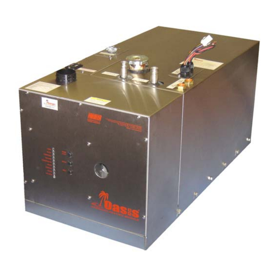
Module is certified only installation into Recreational Vehicles. This section covers critical information you need to know before beginning the installation including how to protect your Warranty, and tools and equipment needed. Figure 1-1: Oasis™ Heating Module International Thermal Research... -
Page 8: Unpacking The Heating Module
If you are not installing the Oasis™ Heating Module right away secure all components so none will be misplaced. Before installing the Oasis™ Heating Module read the rest of this Installation and Operating Manual. It contains critical information for a proper installation. -
Page 9: Oasis™ Heating Module Features
Oasis™ Heating Module Features • Efficient • Clean The Oasis™ Heating Module uses a diesel burner (12 VDC) • Quiet controlled by a multi-functional electronic controller as the primary • Compact source of heating coolant fluid (anti-freeze and water). - Page 10 Reset, and indicator LED’s for operational and diagnostic information. • Distribution Module if installed with built in distribution pumps and heat exchangers for heating multiple zones and also producing domestic hot water. The Zone Board Controls up to five space heating zones. The Oasis™ Heating Module...
-
Page 11: Critical Factors
Pay attention to the installation are: notices of “Danger” “Warning” “Caution” • Mounting location restrictions for the Oasis™ Heating Module, and “Notice” in this optional Distribution Module , and exhaust outlet (to reduce manual. noise, vibration, heat loss, etc.). •... -
Page 12: Equipment, Tools And Skills
Domestic water hose and/or tubing to connect the Distribution Module hose fittings to the domestic water system. • Overflow tank to connect to the Oasis™ Heating Module with clear plastic 3/8” hose; tank must be heavy-duty plastic, with a The Oasis™ Heating Module... -
Page 13: Testing And Inspection
RVIA ABYC standards, recommendations of this Installation and Operating Manual, the Oasis™ Heating Module should be test-operated for inspection purposes. For your convenience, you can use the pullout Inspection Check Sheet in this Manual. The Inspection Check Sheet is divided into... - Page 14 Section Mounting – Oasis™ Heating Module Before You Begin Plan the location of the Oasis™ Heating Module and all its major components in advance to ensure the chosen locations are compatible with installation requirements and within the technical specifications. Consider the following factors to help you decide exactly where best to mount the Oasis™...
-
Page 15: Section 2, Mounting The Oasis™ Heating Module
320lbs./73 KG x 2 = 146 KG) and must be of a non- combustible and non absorptive surface. • Oasis™ Heating Module is 14”H x 14”W x 32” D. (35.6 cm x 35.6 cm x 81.3 cm), see Figure 2-1: Module Dimensions. •... -
Page 16: Figure 2-1 Module Dimensions
Oasis™ Heating Module must not be installed or operated in any ! DANGER compartment with flammable gases. If the Oasis™ Heating Module is going to be mounted in the engine ! WARNING compartment, check for adequate ventilation. When the engine is running this area could be under a negative pressure. -
Page 17: What Not To Do
Isolate the unit in a closed compartment so that no air from the ! DANGER heater will infiltrate the living areas. • It is recommended that a catchpan be placed under the Oasis™ Heating Module for containing any unexpected leakage. • Choose a sturdy surface in a location that won’t be unduly affected by vibration and the jarring of rough roads or rough seas. -
Page 18: Figure 2-2 Module Mounting Brackets
Section 2, Mounting the Oasis™ Heating Module Figure 2-2: Module Mounting Brackets International Thermal Research... -
Page 19: Section 3, Installing The Exhaust System
Section Installing the Exhaust System Before You Begin For efficient and safe operation of the Oasis™ Heating Module follow all recommendations for properly installing the exhaust. deviations from these must be approved in advance by ITR. Although the heater’s exhaust produces very low carbon monoxide... -
Page 20: Recommendation For Installation
• In a coach, the typical mounting location for the exhaust outlet is under the floor of the Oasis™ Heating Module compartment, or on the other side of the coach, directly across from the module. Keep in mind you cannot exceed 12’... - Page 21 • Ensure that the exhaust cannot be plugged or restricted. • The exhaust fitting on the Oasis™ Heating Module is 2.0” O.D. and the exhaust pipe used must have a minimum of 2.0” I.D. throughout its length. •...
-
Page 22: What Not To Do
Don’t use more than 10’ of exhaust pipe if 180° of total bends are present. Don’t use any mufflers not supplied or approved by ITR. Don’t over-tighten exhaust clamps or you may crush the Oasis™ Heating Module’s exhaust outlet pipe. Procedure Figure 3-1: Installing the Exhaust System (Bottom Exhaust) shows a standard setup for the down exhaust. - Page 23 Protect the air-intake entrance from water and dirt with a guard or shield. On a yacht, make sure the thru hull is at least 30” above the waterline and the exhaust must be goose-necked, see Figure 3-3: The Exhaust Goose Neck Configuration. International Thermal Research...
-
Page 24: Figure 3-2 The Exhaust Hole Location & Mounting
Section 3, Installing the Exhaust System Figure 3-1: Installing the Exhaust System (Bottom Exhaust) Figure 3-2: The Exhaust Hole Location & Mounting Template The Oasis™ Heating Module... - Page 25 Section 3, Installing the Exhaust System Figure 3-3: The Exhaust Goose Neck configuration International Thermal Research...
-
Page 26: Section 4, Installing The Fuel System
Any deviations from these must be approved in advance by ITR. Use only diesel fuel, furnace oil, or stove oil in the Oasis™ Heating ! DANGER Module. DO NOT USE GASOLINE, CRANKCASE OIL, OR ANY OIL CONTAINING GASOLINE. -
Page 27: What Not To Do
The fuel supply line should be installed with minimal rise from the fuel tank. The total rise from the bottom of the pickup tube to the fuel inlet on the Oasis™ should not exceed 60”. There are no minimum clearance requirements between the fuel tank and the Oasis™... -
Page 28: Procedure
Install the inline fuel filter. The optimal location is on a compartment wall next to the Oasis™ Heating Module, inline between the fuel tank and the Oasis™ Heating Module. Connect the fuel line to the dedicated fitting on the main diesel fuel tank. - Page 29 The Defrost Heater, provides up to 28,000 BTU/h and uses a three speed fan, 200/275/450 cfm, 40/55/100 watts. Note: A limited number of fan heaters can be used with the Oasis™ Heating and Distribution Modules. Only the installation of ITR fan heaters is covered in this NOTICE Manual.
-
Page 30: Section 5, Installing Fan Heaters
Figure 5-1: Wiring the Fan’s Aquastat shows how to wire up the aquastat in a fan. Figure 5-1: Wiring the Fan’s Aquastat The Oasis™ Heating Module... -
Page 31: Multiple Zone Heating
ITR for recommended installation procedures and design. Multiple Zone Heating The Oasis™ Heating Module can supply heat up to five interior zones using the Distribution Module, DM8 (Optional). Refer to Section 9 – Installing Distribution Module, DM8 (Optional). -
Page 32: What Not To Do
This fan can also be ordered with a right-hand or left-hand hose configuration. ITR’s standard cabin heater fan comes with loose stainless steel brackets. The fan can be mounted on the floor or on the wall, either flat or on its side. The Oasis™ Heating Module... -
Page 33: Procedure
(not the heater’s control board). See Figure 5-3: Installing a Relay for Additional Fan Amperage. To install plumbing lines to the fans, see Section 7 – Plumbing the System. International Thermal Research... -
Page 34: Figure 5-2 Mounting A Spacesaver Fan
Section 5, Installing Fan Heaters Figure 5-2: Mounting a Spacesaver Fan Figure 5-3: Installing a Relay for Additional Fan Amperage The Oasis™ Heating Module... -
Page 35: Section 6, Wiring The Electrical System
Section Wiring the Electrical System Before You Begin The Oasis™ Heating Module and its electrical Control Board are pre- wired and have been thoroughly tested together as a unit. To review the wiring system for the Oasis™ Heating Module, refer to the wiring diagram at the end of this Section 6, Figure 6-1: System Wiring. -
Page 36: 120 Vac
The Oasis™ Heating Module is equipped with two 1500 watt, 120 VAC immersion elements (other voltages and frequencies are available). The connections for the electrical supply are on the top left side of the Oasis™ Heating Module, under a cover, labeled AC power. •... -
Page 37: Main Electronic Control Board
Section 6, Wiring the Electrical System Figure 6-1 System wiring Main Electronic Control Board The main electronic Control Board is mounted onboard the Oasis™ NOTICE Heating Module itself. It has no user adjustable components. Distribution Module Zone Control Board (optional) •... -
Page 38: What Not To Do
Section 6, Wiring the Electrical System What NOT to Do Never shut off the Oasis™ Heating Module power via an inline NOTICE battery or master switch while the system is running. Never disconnect the battery when the Oasis™ Heating Module is running, and never disconnect the battery while the inverter is charging. -
Page 39: Section 7, Plumbing The System
Module, and finally to the cabin fans. Plumbing Installation The plumbing installation should consider the following: • The Oasis™ Heating Module has a filler neck located on the top of the unit and is equipped with a seven (7) pound radiator cap. International Thermal Research... - Page 40 • The return and supply coolant plumbing connections are on the front lower face of the Oasis™ Heating Module and are 1/2” female NPT fittings. The return coolant input to the Oasis™ Heating Module is a connection labeled “Inlet” and the supply coolant output from the Oasis™...
-
Page 41: Figure 7-1 Heating Module
Ensure that the coolant flow is adequate through the Oasis™ Heating Module and the system. An indication of inadequate flow is, when the Oasis™ Heating Module is running and up to normal operating temperature, the difference between the inlet and outlet coolant temperature to the Oasis™ Heating Module is less than 20F. -
Page 42: What Not To Do
What NOT to Do The Oasis™ Heating Module’s circulating water pump is one of the NOTICE most critical parts of the system. Never let the pump run dry or you will damage the impeller. -
Page 43: Heater Hose (Consult Itr For Alternative Methods And Products)
“Inlet” on the Oasis™ Heating Module. Ensure there are no kinks or sharp bends that might restrict the fluid flow. Fill the Oasis™ Heating Module through the filler neck with the recommended propylene glycol/water anti-freeze solution and bleed all trapped air. -
Page 44: Section 8, Operating The Oasis™ Heating Module
INSTRUCTIONS AND SAVE FOR REFERENCE. Features of Your Oasis™ Heating Module The Oasis™ Heating Module uses a diesel burner (12 VDC) controlled by a multi-functional electronic controller as the primary source of heating coolant fluid (anti-freeze and water). Two 1500 Watt, 120 VAC immersion elements are used as secondary heat sources. -
Page 45: Your Heating Module Model
The Oasis™ Heating Module. This is essential for the proper functioning and life of your Oasis™ Heating Module as well as protecting your warranty. Your model can be identified by locating the serial number label on the outside case of the Oasis™... -
Page 46: Operating Instructions For The Oasis™ Heating Module
The two types of Oasis™ Heating Modules are: CH50 – Oasis™ Heating Module 50 CH35 (“CSA Certification Pending”) – Oasis™ Heating Module 35 Operating Instructions for the Oasis™ Heating Module The Oasis™ Heating Module must be installed and connections... -
Page 47: Turning The Power To The Oasis™ Heating Module On
ON and is required to be left ON during any period where heat is requested. • When the Oasis™ Heating Module is shut down for any extended period or the season, it is recommended that the power switch be turned OFF. -
Page 48: Activating The Burner (Primary)
The burner switch on the Remote Operating Panel controls the ON/OFF of the diesel burner (primary heat source). When the burner switch is turned ON, the diesel portion of the Oasis™ Heating Module will turn ON after ten seconds. The Burner LED will turn ON when the diesel burner has been activated. -
Page 49: Activating The Cabin Fan Heaters Through The Thermostats
(Oasis™ Heating Module and Distribution Module used in Tandem) (Burner or AC Heat On) • As long as heat is available in the Oasis™ Heating Module, the Distribution Module, DM8 (Optional) will respond to a call for domestic hot water. -
Page 50: Functions Of The Remote Operating Panel
Panel to the ON position with the burner or AC switch on. The engine preheat pump and coolant pump will be activated once the Oasis™ Heating Module is in its set operating temperature range. The engine will start to be preheated by the Oasis™ Heating Module. •... - Page 51 The engine pre-heat switch (optional) controls the ON/OFF of the engine pre-heat pump (not included). However, the engine pre-heat pump (not included) will not function unless the coolant in the Oasis™ Heating Module has achieved a preset temperature. Burner LED (Green) •...
-
Page 52: Functions Of The Heating Module Control Panel
The reset button when pressed resets the control board. Power LED (Green) • The power LED (green) turns ON when the power to the control board is ON. The LED flashes when the Oasis™ Heating Module is in Bypass mode. AC Heat LED (Green) •... -
Page 53: Functions Of The Distribution Module (Optional) Zone Control Panel
Low Water (Red) • The Low Water LED (red) turns ON when a low coolant level in the Oasis™ Heating Module has been detected. 8.11 Functions of the Distribution Module (Optional) Zone Control Panel • The Distribution Module Zone Control Panel, Figure 8-4: Zone Control Panel, contains seven green LED’s for Power, Zone 1,... -
Page 54: 8.12 Maintenance
The green LED will turn ON when the device is operating normally. The red LED turns ON if a fuse has been blown. 8.12 Maintenance Customer Monthly Maintenance: Check the following and correct as required: International Thermal Research 8-11... - Page 55 • The combustion tube should be inspected by the service technician for wear and replaced if necessary. To access the combustion tube, the front panel of the Oasis™ must be removed along with the burner box cover. The fuel block must then be removed from its mounting position.
-
Page 56: Protecting The Heating Module And Distribution Module (Optional)
8.13 Protecting the Heating Module and the Optional Distribution Module Protect the Oasis™ Heating Module and Distribution Module, DM8 NOTICE (Optional) from temperature extremes and any dusty, dirty, corrosive environment. - Page 57 Fuel filter (external) dirty? Burner Starts but Zone Faults • Power LED on Distribution Module Zone Control Panel glowing green? • Component matched LED pairings all glowing green on the Distribution Module Zone Control Panel? 8-14 The Oasis™ Heating Module...
-
Page 58: Installing Your Distribution Module (Optional)
(minimum of 6” top clearance) with 3” clearance to all other module surfaces. • Module is 12”H x 16”W x 6” D. (30.5 cm x 40.6 cm x 15.3 cm). See Figure 9-1: Distribution Module, DM8. International Thermal Research... -
Page 59: Selecting The Distribution Module Zone Box Location
They are: Domestic Cold Inlet and Domestic Hot Outlet, Space Heat Inlet and Space Heat Outlet, Engine Heat Inlet and Engine Heat Outlet, and Inlet from Heater and Outlet to Heater. the illustration for the location of the fittings. The Oasis™ Heating Module... -
Page 60: Figure 9-2 Distribution Module Fittings Location
3/4” NPT x 3/4" hose barbs (not supplied), 3/4” I.D. heavy duty rubber hose, and good quality hose clamps are recommended for connecting the fittings together. All fittings on the Oasis™ Heating Module and Distribution Module NOTICE require two wrenches when tightening. One wrench must be placed on the tank fitting and held in place to prevent this fitting from being overstressed. -
Page 61: Figure 9-3 Plumbing For Five Zones Using The
The Inlet from Heater is supplied by the hot coolant supply output line of the Oasis™ Heating Module. The Outlet to Heater is the supply to the cold coolant return input line to the Oasis™ Heating Module. Figure 9-3: Plumbing for Five Zones Using the Distribution Module... -
Page 62: 9.5 Electrical Connection
Do not operate the Oasis™ Heating Module and Distribution Module, NOTICE NOTICE DM8 (Optional) until coolant is in the Oasis™ Heating Module and Distribution Module and all trapped air has been bled. All plumbing lines must be run and secured so as to prevent damage, chafing and kinking. -
Page 63: 9.6 Distribution Module Zone Control Board
Cabin Fan leads • The positive (red) lead from each cabin fan is to be attached to one of the trailing cabin fan leads, color coded for zones, from the thermostat and cabin fan connector plug. The Oasis™ Heating Module... -
Page 64: Figure 9-4 Distribution Module Electrical Hookup
(not provided) that is connected to the battery. • The return lead from each thermostat is to be attached to one of the trailing thermostat leads, color coded for zones, from the thermostat and cabin fan connector plug. Figure 9-4: Distribution Module Electrical Hookup International Thermal Research... -
Page 65: Inspection And Testing
After all components have been properly installed according to ABYC Industry Standards and Practices and the recommendations of this Manual, the Distribution Module and Oasis™ Heating Module should be inspected using the Inspection Check Sheet in this Manual. The Inspection Check Sheet is divided into relevant sections... -
Page 66: Warranty Information
Warranty Information Attention Purchaser and Installer NOTICE No warranty covers damage or failure of the heater, hot water heater, heating module, distribution module, or space heating module (collectively, “the Product”) or to the vehicle in which it is installed, due to unapproved, unauthorized, or improper installations of the Product. -
Page 67: Limited Warranty
Warranty Information International Thermal Research Limited Warranty The following warranties are in lieu of all other warranties and conditions. ITR makes no other warranties, representations, or conditions, express or implied. Expressly excluded are all implied or statutory warranties or conditions of merchantability of fitness for a particular purpose, and those arising by statute or otherwise in law or from dealing or trade usage. -
Page 68: Customer Service Calls
International Thermal Research Warranty Information • Original serial number on Product or electrical control board has been removed, altered, or is unreadable. • Product has been modified or uses non-standard parts not approved by ITR. • Product has been abused (such as by dropping it), damaged, vandalized, or has received improper maintenance. - Page 69 Warranty Information International Thermal Research Depending on your location, an authorized service person may be able to visit your coach or yacht to help troubleshoot problems and repair your Product. Such service calls are at the Owner’s expense. Regardless, you must obtain written approval from ITR or the Dealer for any warranty repair before it is undertaken.
Need help?
Do you have a question about the Oasis and is the answer not in the manual?
Questions and answers