Nokia N71 Service Manual
Nokia n71 mobile phone service manual
Hide thumbs
Also See for N71:
- User manual (116 pages) ,
- User manual (17 pages) ,
- User manual (115 pages)
Table of Contents
Advertisement
Quick Links
Download this manual
See also:
User Manual
CMO Operations & Logistics
Training & Vendor Development
Multimedia Creation & Support
Service Manual N71 RM-67/RM-112
Page
CONFIDENTIAL
SERVICE MANUAL
Level 1&2
RM-67
Copyright © 2006 NOKIA Corporation. All rights reserved.
1
(35)
RM-112
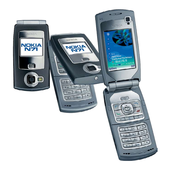
Transceiver characteristics:
DUAL MODE: Tri-band phone for GSM 900/1800/1900MHz and
WCDMA 2100
CAMERA:
- 2 Megapixel camera (1600 x 1200 pixels) with up to 20x digital
zoom
- VGA camera (640 x 480 pixels) with 2x digital zoom
DISPLAY:
Main: Active matrix 2.4" QVGA color display with 262.144 colors,
resolution 320 x 240 pixel
Cover: 1.36" display: Up to 65,536 colors; 96 x 68 pixels,
BLUETOOTH
VISUAL RADIO
CARD TYPE: miniSD™
CONNECTOR: Pop-Port connector
Transceiver with BL-5C 970mAh Li-Ion battery pack
Talk time
up to 4h
Environmental characteristics:
•
Lead-free soldered
Approved 4.0
12.Dec.2006
Standby
Note
Depends on network
up to 9 days
parameters
MGR
Advertisement
Table of Contents

Related Manuals for Nokia N71


Summary of Contents for Nokia N71
- Page 1 CONNECTOR: Pop-Port connector Transceiver with BL-5C 970mAh Li-Ion battery pack Talk time Standby Note Depends on network up to 4h up to 9 days parameters Environmental characteristics: • Lead-free soldered Service Manual N71 RM-67/RM-112 Copyright © 2006 NOKIA Corporation. All rights reserved.
-
Page 2: Table Of Contents
Lid removal instruction deleted Approved 28.Jul.2006 Exploded view and Spare Parts overview updated Approved 12.Dec.2006 Exploded view, Spare Parts overview, Component overview updated, Level 2 Solder components added Service Manual N71 RM-67/RM-112 Copyright © 2006 NOKIA Corporation. All rights reserved. -
Page 3: Introduction
INTRODUCTION The purpose of this document is to help NOKIA service levels 1 and 2 workshop technicians to service NOKIA products. This Service Manual must be used only by authorized NOKIA service suppliers. The content of it is confidential. Please note that NOKIA also provides other guidance documents (e.g. -
Page 4: General Repair Information
There are several documents available on NOL which must be followed: • • First, pay attention to the latest content pages of Service Bulletins, which are always available for each folder on NOKIA Online. Make sure your documentation is up to date. •... -
Page 5: Pathfinder For Workshop Staff
Videos – Disassembly/Assembly NOKIA Online Care Services Training Phone Models Level 1&2 e-learning courses offer a quick overview of the NOKIA phone and support on repair and testing. Overview & Guides Disassembly & Assembly Troubleshooting Basic information about the phone,... -
Page 6: Exploded View And Component Disposal
EXPLODED VIEW AND COMPONENT DISPOSAL Recommendation for the ecologically friendly disposal of components. Colorized components show the different catego- ries. See corresponding ITEM/CIRCUIT REF in the Spare Parts Service Bulletins on NOL. Service Manual N71 RM-67/RM-112 Copyright © 2006 NOKIA Corporation. All rights reserved. -
Page 7: Spare Parts Overview
Page (35) Approved 4.0 CMO Operations & Logistics Training & Vendor Development 12.Dec.2006 Multimedia Creation & Support CONFIDENTIAL SPARE PARTS OVERVIEW Service Manual N71 RM-67/RM-112 Copyright © 2006 NOKIA Corporation. All rights reserved. -
Page 8: Component Overview
Page (35) Approved 4.0 CMO Operations & Logistics Training & Vendor Development 12.Dec.2006 Multimedia Creation & Support CONFIDENTIAL COMPONENT OVERVIEW Service Manual N71 RM-67/RM-112 Copyright © 2006 NOKIA Corporation. All rights reserved. -
Page 9: Level 2 Solder Components
Page (35) Approved 4.0 CMO Operations & Logistics Training & Vendor Development 12.Dec.2006 Multimedia Creation & Support CONFIDENTIAL LEVEL 2 SOLDER COMPONENTS Service Manual N71 RM-67/RM-112 Copyright © 2006 NOKIA Corporation. All rights reserved. -
Page 10: Spare Parts List
(spare parts, SWAP units and service tools). This will ensure that you are using up-to-date order codes only. Therefore, Service Bulletins have to be checked from NOL on daily basis. Service Manual N71 RM-67/RM-112 Copyright © 2006 NOKIA Corporation. All rights reserved. -
Page 11: Service Tools
Small and lightweight stereo headset for handsfree functionality and listening to FM radio. SS-51 VGA Camera Removal Tool. CA-53 Service Cable to connect the PC with the Pop-Port™ connector Service Manual N71 RM-67/RM-112 Copyright © 2006 NOKIA Corporation. All rights reserved. - Page 12 Wetec tweezers 13 SA-SMD ESD • Wetec tweezers PSF SA-ESD • Wetec ESD brush E1211 • Kaiser Fototechnik airbrush 6315 • Wetec dental tool DEM83266/0 • Components Scissors 323-5732 Service Manual N71 RM-67/RM-112 Copyright © 2006 NOKIA Corporation. All rights reserved.
-
Page 13: Sw-Update
To use FLS-4S Flash Dongle you have to follow the user guide inside the sales package. Please check always for the latest version of flash software, which is available on NOKIA Online. Service Manual N71 RM-67/RM-112 Copyright © 2006 NOKIA Corporation. All rights reserved. -
Page 14: Disassembly Instruction
5. Open the A-COVER ASSY by lifting it with the SRT-6 on the 6. Unlock the A-COVER. shown side. 7. Unlock the other side of the A-COVER. 8. Release the clips on both sides. Service Manual N71 RM-67/RM-112 Copyright © 2006 NOKIA Corporation. All rights reserved. - Page 15 14. Then unlock the SHIELD LID ASSY by using a dental tool. Do the same on both sides. 15. Take care to the grounding springs when removing the 16. Gently, open the LCD connector. SHIELD LID ASSY. Service Manual N71 RM-67/RM-112 Copyright © 2006 NOKIA Corporation. All rights reserved.
- Page 16 SS-51. 23. First, unlock the clip on the shown side. 24. Then, release the snap in the middle of the cover with a slot- ted screwdriver. Service Manual N71 RM-67/RM-112 Copyright © 2006 NOKIA Corporation. All rights reserved.
- Page 17 29. Protect the LCD with a film and remove it from the LID CENTER 30. Push the EARPIECE out of its guidance. FRAME. 31. Remove the MAGNET. 32. Remove the HINGE COVERS. Service Manual N71 RM-67/RM-112 Copyright © 2006 NOKIA Corporation. All rights reserved.
- Page 18 40. Unscrew the two, Torx Plus ® size 5 SCREWS in the order 39. Remove the SCREW CAPS with the SRT-6. Note: Do not reuse the SCREW CAPS. shown. Service Manual N71 RM-67/RM-112 Copyright © 2006 NOKIA Corporation. All rights reserved.
- Page 19 46. Remove the KEYMAT MENU. 47. Gently, remove the MENU KEY SURROUNDING ASSY. 48. Feed the FLEX through the slide in the C-COVER. Please note: This part must not be reused. Service Manual N71 RM-67/RM-112 Copyright © 2006 NOKIA Corporation. All rights reserved.
- Page 20 55. Open the SD DOOR and check, that the MINI SD card has been 56. Remove the ENGINE MODULE. removed from its slot, before removing the ENGINE MODULE from the D-COVER. Service Manual N71 RM-67/RM-112 Copyright © 2006 NOKIA Corporation. All rights reserved.
- Page 21 61. Carefully, disconnect LZ BT MODULE from the ENGINE BOARD. 62. Remove the CENTER SHIELD paying attention to the Battery Connector. 63. Lift out the DC-JACK with the DC-Plug. 64. Remove the MICROPHONE with the dental pick. Service Manual N71 RM-67/RM-112 Copyright © 2006 NOKIA Corporation. All rights reserved.
-
Page 22: Assembly Instruction
6. Insert the EARPIECE with the new IHF SPEAKER ADHESIVE into the D-COVER IHF LID. 7. Fit the IHF LID in the D-COVER. 8. Place the IHF SHIELD on the D-COVER. Service Manual N71 RM-67/RM-112 Copyright © 2006 NOKIA Corporation. All rights reserved. - Page 23 COVER. 15. To prevent damaging the plastic thread, turn the SCREW 16. Fit the C-COVER SLIDE. slightly left first. Then tighten it with a torque setting of 17Ncm. Service Manual N71 RM-67/RM-112 Copyright © 2006 NOKIA Corporation. All rights reserved.
- Page 24 Then tighten it with a torque setting of 17Ncm. 23. Gently, close the FLEX connector. 24. Carefully, feed the FLEX through the slot in the C-COVER by securing the closed connector. Service Manual N71 RM-67/RM-112 Copyright © 2006 NOKIA Corporation. All rights reserved.
- Page 25 30. Press the SCREW CUPS into its place. 31. Very carefully, assemble the LID CENTER FRAME paying atten- 32. Push the BUSHING into its place to secure the LID CENTER tion to the FLEX. FRAME. Service Manual N71 RM-67/RM-112 Copyright © 2006 NOKIA Corporation. All rights reserved.
- Page 26 38. Position the CAMERA MAIN ASSY on the LR LID PWB and close the CAMERA connector. 39. Ensure the correct position of the VGA CAMERA MODULE and 40. Insert the EARPIECE. insert it into its housing. Service Manual N71 RM-67/RM-112 Copyright © 2006 NOKIA Corporation. All rights reserved.
- Page 27 47. To prevent damaging the plastic threads, turn the screws 48. Close the LCD connector. slightly left first. Then tighten them in the shown order with a torque setting of 17Ncm. Service Manual N71 RM-67/RM-112 Copyright © 2006 NOKIA Corporation. All rights reserved.
- Page 28 53. Close the snaps on the both sides of the upper block. 54. Fit the A-COVER ASSY. Start at the shown side. 55. Close the A-COVER. 56. Finally, fit the BATTERY COVER. Service Manual N71 RM-67/RM-112 Copyright © 2006 NOKIA Corporation. All rights reserved.
-
Page 29: Legend For Quick Trouble Shooter
Page (35) Approved 4.0 CMO Operations & Logistics Training & Vendor Development 12.Dec.2006 Multimedia Creation & Support CONFIDENTIAL LEGEND FOR QUICK TROUBLE SHOOTER Service Manual N71 RM-67/RM-112 Copyright © 2006 NOKIA Corporation. All rights reserved. -
Page 30: Quick Trouble Shooter Part
Page (35) Approved 4.0 CMO Operations & Logistics Training & Vendor Development 12.Dec.2006 Multimedia Creation & Support CONFIDENTIAL QUICK TROUBLE SHOOTER PART 1 Service Manual N71 RM-67/RM-112 Copyright © 2006 NOKIA Corporation. All rights reserved. -
Page 31: Quick Trouble Shooter Part
Page (35) Approved 4.0 CMO Operations & Logistics Training & Vendor Development 12.Dec.2006 Multimedia Creation & Support CONFIDENTIAL QUICK TROUBLE SHOOTER PART 2 Service Manual N71 RM-67/RM-112 Copyright © 2006 NOKIA Corporation. All rights reserved. -
Page 32: Quick Trouble Shooter Part 3
Page (35) Approved 4.0 CMO Operations & Logistics Training & Vendor Development 12.Dec.2006 Multimedia Creation & Support CONFIDENTIAL QUICK TROUBLE SHOOTER PART 3 Service Manual N71 RM-67/RM-112 Copyright © 2006 NOKIA Corporation. All rights reserved. -
Page 33: Quick Trouble Shooter Part 4
Page (35) Approved 4.0 CMO Operations & Logistics Training & Vendor Development 12.Dec.2006 Multimedia Creation & Support CONFIDENTIAL QUICK TROUBLE SHOOTER PART 4 Service Manual N71 RM-67/RM-112 Copyright © 2006 NOKIA Corporation. All rights reserved. -
Page 34: Gonogo Test
Training & Vendor Development 12.Dec.2006 Multimedia Creation & Support CONFIDENTIAL GONOGO TEST To test the Camera, Bluetooth and IRDA functionality refer to the N71 User`s guide. The User´s Guide is available on www.nokia.com. Before starting the GoNoGo test, check that camera window is clean. -
Page 35: Battery Test
Training & Vendor Development 12.Dec.2006 Multimedia Creation & Support CONFIDENTIAL BATTERY TEST A battery tester lets you test the capacity of NOKIA batteries. Please refer to the actual information on NOKIA Online. http://www.astratec.co.uk/ http://www.cadex.com/ Service Manual N71 RM-67/RM-112 Copyright © 2006 NOKIA Corporation. All rights reserved.
Need help?
Do you have a question about the N71 and is the answer not in the manual?
Questions and answers