Table of Contents
Advertisement
Advertisement
Table of Contents

Subscribe to Our Youtube Channel
Related Manuals for Ier 506


Summary of Contents for Ier 506
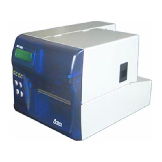
- Page 1 IER 506 PRINTER N06802A Revision Level 4 Feb. 20, 2006...
- Page 2 The warranty shall be null and void in case of use of any spare part, special tool or consumable part not expressly approved in writing by IER and in the event of attempted repair or servicing of the machines by persons lacking the requisite technical qualifications.
-
Page 3: Table Of Contents
Table of Contents A INTRODUCTION ....................4 B CONTENTS OF THE SHIPPING CONTAINER ..........6 C DESCRIPTION ....................7 1) Physical Characteristics................... 7 2) Front View........................ 9 3) Rear View ......................10 4) Opening the Right Side Door ................. 11 5) Interior View...................... -
Page 4: A Introduction
The print technology used by this printer is the direct thermal method requiring the use of heat-sensitive media. The IER 506 Printer accepts fanfold media (see Fig. 1 and Fig. 4) and roll media (see Fig. 2 and Fig. 3) for bag tag and ATB1 flight coupon printing. - Page 5 Fig. 1 Fig. 2 Fig. 3 Fig. 4...
-
Page 6: B Contents Of The Shipping Container
In the box you will find the following: • IER 506 Printer (1) • IER 506 Printer User Guide (2) (present document) • Test documents (3), one of which being the printout of the IER 506 Printer configuration • AC power cord (4) -
Page 7: Cdescription
DESCRIPTION 1) Physical Characteristics Overall printer dimensions, cover open, without roll media shaft: • Depth (A) 300 mm (11.8 in) • Height (cover open) (B) 368 mm (14.5 in) approx. • Width (cover open) (C) 300 mm (11.8 in) approx. Fig. - Page 8 Overall printer dimensions with the covers closed and the media shaft installed: • Depth (A) 500 mm (19.69 in) • Height (B) 226 mm (8.9 in) (feet included) • Width (C) 200 mm (7.87 in) Weight: • Without any options 7 kg (15.4 lbs.), approx. •...
-
Page 9: Front View
2) Front View • Front panel (1) (see Paragraph E3) including the following: Four-line, 20-character per line alphanumeric Liquid Crystal Display (LCD) (2) Four LED indicators (3) Four keys (4) Ejection slot (5) • Hinged right side door (6), fitted with a latch (7), giving access to the printer interior (paper path, thermal printhead module) Fig. -
Page 10: Rear View
3) Rear View • Electronics cover (1) with the following elements on the rear panel of the electronics compartment: AC line power connector (2) AC power switch (3) Data I/O, 25-contact female connector (4) • Media insertion slot (5) made up of two adjustable paper guides •... -
Page 11: Opening The Right Side Door
4) Opening the Right Side Door To open the right side door (1), simply proceed as follows: • Push latch (2) upward. • Swing the right side door (1) open and fold it onto the printer top. Fig. 10... -
Page 12: Interior View
5) Interior View Opening the right side door gives access to the following elements located on the paper path side of the printer and allows the operator to carry out basic operations regarding these elements (described in the present document): •... -
Page 13: Dinstallation
INSTALLATION 1) Setting Up the Printer a) Remove the printer from the shipping container. b) Place it on an even and stable surface providing enough clearance so you can fully open the covers. 2) Connecting the Printer to the Host IMPORTANT: To connect the printer to the host, it is essential to use a shielded cable fitted with metal plated connector hoods. -
Page 14: Connecting The Printer To The Ac Power - Power-Up
3) Connecting the Printer to the AC Power - Power-Up a) Make sure the printer is switched off by checking that the AC power switch at the rear of the printer is set to the 0-position. Fig. 14 b) Connect the AC power cord first to the AC power connector located at the rear of the printer, then to the line power outlet. - Page 15 Power up the printer by setting the power switch to the I-position. Fig. 16 d) The display lights up. After 9 to 10 seconds, approximately, one of the following two messages appears: IER 506 OFF LINE MODE if the printer is off line, or: IER 506...
-
Page 16: Adjusting The Paper Path
4) Adjusting the Paper Path Before using the printer for the first time and when changing the media width, you need to adjust the paper path. IMPORTANT: Loosen the paper path locking wheel before attempting to change the paper path width. Also, be sure the AC power switch is set to the 0-position. - Page 17 d) Fine-adjust the paper path width while leaving enough play (J, see Figure below) to ensure that paper feed is smooth and accurate at the same time Fig. 19 e) Tighten the paper path locking wheel. Fig. 20 f) Close the right side door. IMPORTANT: To avoid a possible paper jam, check that the media runs freely along the paper path.
-
Page 18: Loading Fanfold Media
5) Loading Fanfold Media Fanfold media loading can be performed in the following two ways: a) Preliminary Steps: • Install a box of fanfold media (3) at the rear of the printer. The box must be placed parallel to the printer. Orient the box so that the media, when inserted into the printer, has its heat- sensitive side facing up. - Page 19 Fig. 21...
-
Page 20: Loading Roll Media
6) Loading Roll Media a) Preliminary Steps (Roll Media Shaft with Removable Flange): Refer to the Figure of Page 21. • Remove flange (1) from shaft (2). • When installing the media roll (3) on shaft (2), make sure that the heat-sensitive side (4) of the leading document will be facing up when inserted into the printer. - Page 21 Fig. 22...
- Page 22 Fig. 23 Fig. 24 Fig. 25 Fig. 26...
-
Page 23: E Operation
OPERATION 1) Printing a Document a) Power up the IER 506 Printer (see Page 14). • If the display reads: IER 506 OFF LINE MODE press the On/Off Line key to switch to on line mode: IER 506 ON LINE MODE •... -
Page 24: Removing Blank Media From The Printer Interior
Automatic Media Removal: • Press the On/Off Line key to switch to the off line mode. The display will show the following: IER 506 OFF LINE MODE • Press the Reset key several times to remove the media (1) from the drive mechanism. -
Page 25: Key, Led Indicator And Sound Alarm Functions
It is possible to inhibit this function from the Configuration menu Paper Feed (see IER 506 Printer Technical Manual). Self-Test and Configuration menus: depending on the situation, this key selects the previous menu, the previous parameter or... - Page 26 b) LED Indicator Functions Operating Mode Indicator On Line Mode Off Line Mode When on, indicates that the When off, shows that the printer is in on line mode. It is printer is in off line mode. The On/Off ready to receive messages Self-Test and Configuration from the host.
-
Page 27: Self-Test Mode
4) Self-Test Mode Selecting the Self-Test Mode a) Power up the IER 506 Printer by setting the power switch to the I-position. b) Press the On/Off Line key to select the off line mode. c) Check that the On/Off LED goes off and that the display reads... - Page 28 • Press Test twice to print the bar code test document (reference document for bar code legibility tests). • Press Test three times to print the logo test document (shows the logos available to the printer). • Press Test four times to print the character set test document (shows the character sets available to the printer).
-
Page 29: F Periodic Maintenance
The periodic maintenance recommended for this printer consists of the following three successive operations: dust removal, cleaning the printhead and the platen, final check. The IER cleaning kit (IER P/N S32129A) allows you to efficiently perform these operations. 1) Removing Dust from the Printer Interior... - Page 30 c) Remove the media from the printer. d) Use the dust remover from the cleaning kit and blow compressed air into the printer insertion and output slots. e) Also use the can with compressed air to clean the mechanical assemblies, the sensor(s) and the paper path (see the Figure of Page 30).
-
Page 31: Setting The Printhead To The Cleaning Position
2) Setting the Printhead to the Cleaning Position IMPORTANT: To set the printhead to the cleaning position, first raise the printhead lever (see Page 29). Be careful, not to hit the printhead. a) Raise the printhead lever (see Page 29) b) Then, unlock the printhead mounting by moving it sidewise (direction of Arrow 1). -
Page 32: Cleaning The Platen And The Printhead
Use the dust remover can to dry the cleaned platen. Fig. 33 IMPORTANT: To clean the printhead, use the alcohol filled foam swabs contained in the bag carrying the IER P/N T106140. -
Page 33: Final Check
d) Follow the instructions on the bag to adequately prepare the alcohol filled foam swab for printhead cleaning. e) Using the alcohol filled foam swab, carefully rub the entire line of the printhead heating elements. f) To set the printhead to its initial position, proceed as follows: •... -
Page 34: G Operating Faults
OPERATING FAULTS Operating faults usually generate an error message on the display and/or may cause a document jam inside the printer. NOTE: The sound alarm informs you of an error condition. Note the error message displayed and press the Reset key before you start to solve the problem. - Page 35 Fig. 35...
-
Page 36: Clearing A Media Jam On Printers With Motorized Stacker
2) Clearing a Media Jam on Printers with Motorized Stacker To clear a media jam inside the printer the procedure is identical to the one outlined previously. Follow the procedure below for jams at the output slot or in the motorized stacker (see Fig. -
Page 37: List Of Error Messages
Fig. 37 3) List of Error Messages IMPORTANT: If the recommended action fails to solve the problem, call the help desk. a) Error Messages Intended for the Help Desk The error messages not appearing in the alphabetical list below, are addressed to the Systems Engineer or the Help Desk. - Page 38 b) Error Messages Intended for the Operator IMPORTANT: Having solved the problem encountered, always confirm the corrective action by pressing the Reset key. RECEPT. DEFAULT Syntax error in host message erron. message Send the command again. If this results in a second failure, call the help desk.
-
Page 39: Other Operating Problems
4) Other Operating Problems Printer Does Not Operate: • Power down the printer (set the AC power switch to the 0- position). • Check the AC line power by plugging in another electrical appliance. • Check that the AC power cord is correctly plugged into the line power outlet and the power connector on the printer (see Page 14). -
Page 40: H Cleaning Supplies And Technical Documentation
CLEANING SUPPLIES TECHNICAL DOCUMENTATION The technical documentation and the supplies necessary to regularly service the printer can be ordered from the IER subsidiary covering your geographical area (see back cover). 1) List of the Cleaning Supplies IER P/N • S32129A Standard cleaning kit •... - Page 44 # 09-01/03 Central Plaza SINGAPORE 168730 Phone: +65 6276 6966 Fax: +65 6271 5563 SPAIN IER Impresoras Especializadas, S.L. Calle Comandante Zorita 4 – E 28020 MADRID Phone: +34 91 535 89 75 Fax: +34 91 535 89 76 IER SIEGE / HEADQUARTERS 3, rue Salomon de Rothschild –...
Need help?
Do you have a question about the 506 and is the answer not in the manual?
Questions and answers