Table of Contents
Advertisement
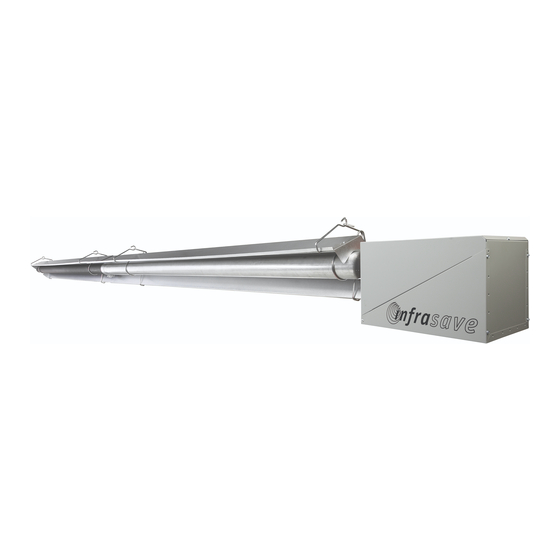
Model
S100 - S100U
LOW INTENSITY TUBE TYPE INFRARED HEATERS
INSTALLATION / OWNER'S MANUAL
WARNING
SAFETY ALERT:
This heater must be installed and serviced only by a trained gas service techni-
cian. Failure to comply could result in personal injury, death, fire and/or property
damage.
Do not store or use gasoline or other flammable vapours and liquids in the
vicinity of this or any other gas fired appliance.
IF YOU SMELL GAS:
Extinguish any open flame
Do not attempt to light this or any other appliance
Don't touch any electrical switch, or telephone
Immediately call your gas supplier from a neighbor's phone
Follow any and all instruction from your gas supplier
If your gas supplier is not available, call the fire department
FIELD CONVERTIBILITY:
This appliance is field con-
vertible to LP gas.
&
Improper installation, adjustment, alteration, service or
maintenance can cause property damage, injury or death.
Read the installation and operating and maintenance instruc-
tions thoroughly before installing or servicing this equipment.
Keep this manual in a secure place .
Record for future reference:
Model #:
Serial #:
(located on heater rating label)
Model
ITB - ITBU
S100/ITB I&O Manual
IM101230
RD: JAN 2012
RL: 6B- BA
Advertisement
Table of Contents

Subscribe to Our Youtube Channel
Related Manuals for Schwank S100

Summary of Contents for Schwank S100
- Page 1 Model Model S100 - S100U ITB - ITBU & LOW INTENSITY TUBE TYPE INFRARED HEATERS INSTALLATION / OWNER’S MANUAL Improper installation, adjustment, alteration, service or WARNING maintenance can cause property damage, injury or death. Read the installation and operating and maintenance instruc- tions thoroughly before installing or servicing this equipment.
- Page 2 The Manufacturer. Unauthorized use or distribution of this publication is strictly prohibited. Schwank Group Schwank and InfraSave brands 5285 Bradco Boulevard Mississauga, Ontario,L4W 2A6 PO Box 988, 2 Schwank Way Waynesboro, Georgia 30830 Customer & Technical Services Phone: 877-446-3727 Fax: 866-361-0523 e-mail: csr@schwankgroup.com www.schwankgroup.com...
-
Page 3: Table Of Contents
S100 - S100U and ITB - ITBU SERIES GAS FIRED INFRARED LOW INTENSITY TUBE TYPE TABLE OF CONTENTS TOPIC ……...PAGE TOPIC ..PAGE 13. GAS SUPPLY ..........29 INSTALLATION HEATER EXPANSION........30 IMPORTANT INFORMATION - READ FIRST FLEXIBLE GAS CONNECTION.......30 APPLICATION ..........4 14. ELECTRICAL AND THERMOSTAT....32 HEATER EXPANSION ......5, 31... -
Page 4: Application
Revisions to codes and/or standards, may require revision to equipment and installation proce- dures. In case of discrepancy, the latest codes, standards, and installation manual will take pri- ority over prior releases. Models S100 and ITB may be installed for heating of commercial / industrial non- residential indoor spaces. -
Page 5: Heater Expansion
. Ensure that there is sufficient ventilation to adequately clear any smoke from the space. Notify site and safety personnel to ensure that alarm systems are not unduly activated. S100/ITB I&O Manual IM101230 RD: JAN 2012 RL: 6B- BA... -
Page 6: Clearance To Combustibles
Refer to Figure 1 and Table 1 for the certified clearances to combustibles for the appro- priate model input/size. S100/ITB I&O Manual IM101230 RD: JAN 2012 RL: 6B- BA... -
Page 7: Clearances Figure & Table
32 (81) 60 (152) S100(U)/ITB(U) 110 9 (23) 3 (8) 36 (92) 54 (137) 9 (23) 30 (76) 60 (152) S100 /ITB 100 10 (26) 4 (10) 57 (145) 68 (172) 11 (28) 32 (81) 68 (172) S100(U)/ITB(U) 80 7 (18) -
Page 8: Stacking Height Sign New
Refer to the information for the heater model being installed in Figure 1 and Table 1 to get the values for dimensions ‘S’, ‘F’ and ‘B’. Post this sign as instructed above. S100/ITB I&O Manual IM101230 RD: JAN 2012 RL: 6B- BA... -
Page 9: Labor Requirements
Use for process or other applications that are not space heating will void the C.S.A. certification and product warranty. Process application requires field inspection and/or certification by local authorities having jurisdiction. S100/ITB I&O Manual IM101230 RD: JAN 2012 RL: 6B- BA... -
Page 10: Pre-Installation Survey
ANSI/NFPA N0 70 in the U.S.A. and PART 1 CSA C22.1 in Canada must also be observed. The heating system must have gas piping of the correct diameter, length, and arrangement to function properly. For this reason, a layout drawing is necessary. S100/ITB I&O Manual IM101230 RD: JAN 2012... -
Page 11: Mounting Clearances
24 inches (61 cm) to any ONE side to allow servicing of burner, blower and controls. (see Fig- ure 2) - the minimum clearances to combustibles must always be maintained. For guidelines to heater placement refer to TABLE 2 (below). FIGURE 2 S100/ITB I&O Manual IM101230 RD: JAN 2012 RL: 6B- BA... -
Page 12: Heater Placement Guidelines
HEIGHT HEATERS ANGLE “U-Tube” ft (m) ft (m) ft (m) S100 / ITB 200 18 – 25 (6 - 8) 50 (15) 17 – 25 (5 - 8) S100 / ITB 175 18 – 25 (6 - 8) 50 (15) 17 –... -
Page 13: Elbow Kit Dimensions
90° elbows (JS-0528-SM) are shipped as a kit with one coupler, and two reflector end caps. The S100 / ITB is available in a “U-Tube” model - S100U / ITBU - using a 180° turn box. A double wide reflector covers the double tube run. Alternately, for a 180° elbow, order 2 x 90°... -
Page 14: Suspending The System
WITH HOOK OR CLAMP BOLT THROUGH OR CLEVIS NOTE: It is the installer’s responsibility to ensure that mounting hardware and fastening to structure are of sufficient strength to support the system. S100/ITB I&O Manual IM101230 RD: JAN 2012 RL: 6B- BA... -
Page 15: Burner & Tube Installation
9 INSTALLATION OF HANGERS, TUBES AND BURNER STRAIGHT TUBE SYSTEM 9.1 S100 / ITB ~ BURNER AND TUBE INSTALLATION Note: The turbulator for the 175,000 LP heater must always be in the 5th tube. Turbulators for all other inputs are ALWAYS installed at the vent end of the heater. - Page 16 (end of downstream tube) 6 Tighten bolts to 40 ft-lbs. FIGURE 10 HANGER / REFLECTOR ORIENTATION HORIZONTAL TO 45 FOR ANGLE LESS THAN 45° USE CHAIN TO BOTH EYES ON HANGER 45° 45° S100/ITB I&O Manual IM101230 RD: JAN 2012 RL: 6B- BA...
-
Page 17: U' Tube System
The ‘long’ leg attaches to the burner-run tubes The ‘short’ leg attaches to the vent-run tube side - tubes end short of burner for con- nection of vent pipe S100/ITB I&O Manual IM101230 RD: JAN 2012 RL: 6B- BA... - Page 18 12 - HANGER SUPPORT ADAPTER 7 - TORCTITE TUBE COUPLER CHAINS FIGURE 12 ‘U’ TUBE MODELS ‘U’ TUBE HANGER FIGURE 12A TURN BOX FIGURE 12B FIGURE 13 ‘U’ TUBE MODEL ORIENTATION S100/ITB I&O Manual IM101230 RD: JAN 2012 RL: 6B- BA...
- Page 19 This will result in the best performance radiant output from the system. S100/ITB I&O Manual IM101230 RD: JAN 2012 RL: 6B- BA...
-
Page 20: Sesmic Restraint
Schwank / InfraSave offers optional items: #2 Lion Chain 115 lb work load x 200 ft roll (PN: JL- 0800-XX); and Safety Snap Hooks (PN: JL-0800-SH = pkg 24; JL-0800-SH-B = pkg 100). -
Page 21: Seismic Restraint 'U'-Tube
Schwank / InfraSave offers optional items: #2 Lion Chain 115 lb work load x 200 ft roll (PN: JL- 0800-XX); and Safety Snap Hooks (PN: JL-0800-SH = pkg 24; JL-0800-SH-B = pkg 100). -
Page 22: Reflector Installation
NOTE: Ensure that you are installing a single reflector - reflectors can ‘stick together’ in packaging - take care to separate them. S100 / ITB - STRAIGHT TUBE : After burner and tubes have been installed, slide the re- flectors one at a time into the wire hangers. As each successive reflector is installed on an in- line installation, the ends of the reflectors will overlap to provide continuous coverage over the entire tube system. - Page 23 5. Insert “S” hook down through hole in the top of the reflector extension 6. Rotate “S” hook approx. 90°, and insert into hole drilled in reflector 7. Settle reflector extension into place Insert ‘S’ hook from top and rotate S100/ITB I&O Manual IM101230 RD: JAN 2012 RL: 6B- BA...
-
Page 24: Flue Venting
Tee (10 x 10 x 15 cm), supplied by the manufacturer. Vent pipe from each heater does not need to be equidistant to the vent Tee, but must comply to requirements below. The two S100/ITB I&O Manual IM101230 RD: JAN 2012... - Page 25 The flue vent system must slope downwards approximately 1/4" per ft (63 mm/ 300 mm) toward the vent terminal, starting at the termination of the radiant tube - radiant tube must be level. S100/ITB I&O Manual IM101230 RD: JAN 2012...
- Page 26 12 inches (30 cm) for inputs up to and including 100,000 Btuh (30 kW) 3 ft (90 cm) for inputs exceeding 100,000 Btuh (30 kW) S100/ITB I&O Manual IM101230 RD: JAN 2012 RL: 6B- BA...
-
Page 27: Combustion Air Duct
Inputs: 45, 60, 80, 100, and 110 Mbh: 50 feet maximum combined vent & duct Total combined vent and duct is reduced by ten feet for every 90° elbow installed in the vent or duct and in the tube system. S100/ITB I&O Manual IM101230 RD: JAN 2012 RL: 6B- BA... - Page 28 Fire Mar- shall and Department of Labor for possible contaminants and any conflict with the installation of hot surface heating equipment. S100/ITB I&O Manual IM101230 RD: JAN 2012 RL: 6B- BA...
-
Page 29: Gas Supply
“drip leg” in the gas line can cause property damage, injury or death and will void the heater warranty. TABLE 4 LINE PRESSURE MANIFOLD PRESSURE INCHES WATER COLUMN GAS TYPE (tap at gas valve outlet) INCHES WATER COLUMN MINIMUM MAXIMUM Natural Gas 14.0 S100/ITB I&O Manual IM101230 RD: JAN 2012 RL: 6B- BA... -
Page 30: Heater Expansion
3/4” x 36” - JL-0771-RB 200,000 2 3/4” 3/4” x 36” - JL-0771-YY 3/4” x 36” - JL-0771-RB 200,000 60 / 70 3 1/4” 3/4” x 36” - JL-0771-YY 3/4” x 36” - JL-0771-RB S100/ITB I&O Manual IM101230 RD: JAN 2012 RL: 6B- BA... -
Page 31: See Also "Flexible Gas Connection
The flue vent, and combustion air duct (if installed) must also be configured in such a manner that the normal expansion of the heater will be accommodated. See Section 11. S100/ITB I&O Manual IM101230 RD: JAN 2012 RL: 6B- BA... -
Page 32: Electrical And Thermostat
THE TUBE HEATER BURNER IS COMPLETELY FACTORY ASSEMBLED AND TESTED. ANY ALTERATION VOIDS THE CSA CERTIFICATION AND MANUFACTURER’S WARRANTY. FOR ADDITIONAL INFORMATION, CONTACT YOUR LOCAL DISTRIBUTOR OR MANUFACTURER. S100/ITB I&O Manual IM101230 RD: JAN 2012 RL: 6B- BA... - Page 33 ANSI / NFPA 70 or current Canadian Electrical code CSA C22.1. A maximum night set-back of 9°F (5°C) is recommended for optimum economy and comfort. To maintain satisfactory comfort levels do not turn off the heating system over night/weekends. S100/ITB I&O Manual IM101230 RD: JAN 2012...
-
Page 34: Volt Thermostat
ANSI / NFPA 70 or current Canadian Electrical code CSA C22.1. A maximum night set-back of 9°F (5°C) is recommended for optimum economy and comfort. To maintain satisfactory comfort levels do not turn off the heating system over night/weekends. S100/ITB I&O Manual IM101230 RD: JAN 2012... -
Page 35: Line Voltage Thermostat
ANSI / NFPA 70 or current Canadian Electrical code CSA C22.1. A maximum night set-back of 9°F (5°C) is recommended for optimum economy and comfort. To maintain satisfactory comfort levels do not turn off the heating system over night/weekends. S100/ITB I&O Manual IM101230 RD: JAN 2012... -
Page 36: Sequence Of Operation
#1 9. If the blower does not run, the blower air pressure switch (normally open contact) does not close and power is not supplied to the ignition control. S100/ITB I&O Manual IM101230 RD: JAN 2012... -
Page 37: Troubleshooting Guide
CHECK SPARK GAP SETTING IS 3/16” (ADJUST BY MOVING THE GROUND PRONG ONLY) PERFORM IGNITION LEAD TEST (See SPARK IGNI- TION CIRCUIT INSTRUCTIONS—Section 22) CONTINUED GOOD SPARK..REPLACE IGNITER NO SPARK/OR WEAK..REPLACE CONTROL S100/ITB I&O Manual IM101230 RD: JAN 2012 RL: 6B- BA... - Page 38 CHECK FOR FAULTY WIRING, REMOVE GAS VALVE LEAD AT CONTROL , IF VALVE CLOSES, RECHECK THE TEMPERATURE CONTROLLER AND WIRING. IF VALVE STAYS OPEN..REPLACE GAS VALVE TROUBLESHOOTING ENDS SEE S87J DSI CHECK S100/ITB I&O Manual IM101230 RD: JAN 2012 RL: 6B- BA...
-
Page 39: Spark Ignition Circuit
3/16” 1/4” “booklet” format (8.5” x 11” folded in half) use these bars 1/4” 3/16” IF this manual is 8.5” x 11” “full page” format use these bars S100/ITB I&O Manual IM101230 RD: JAN 2012 RL: 6B- BA... -
Page 40: Flame Sensing Circuit
If gas good rectifying flame. pressure is correct check line and orifice for ob- Check gas pressure and gas ori- fice for insects, and spider webs. structions. S100/ITB I&O Manual IM101230 RD: JAN 2012 RL: 6B- BA... -
Page 41: Start- Up / Commissioning Sheet
“burn off” and create smoke during the first hour of operation. This is temporary and normal. Please ensure that there is sufficient ventilation to adequately clear the smoke from the space. Notify site and safety personnel to ensure that alarm systems are not unduly activated. S100/ITB I&O Manual IM101230 RD: JAN 2012... - Page 42 IF INSTALLED..IS TURBULATOR AT FLUE END OF SYSTEM “MAXIMUM STACKING HEIGHT” SIGN(S) - POSTED AT THERMOSTAT(S) THIS HEATER MUST BE ELECTRICALLY GOUNDED 1-866-361-0523 1-877-446-3727 FAX COMPLETED REPORT TO TECHNICAL SERVICES: FAX , VOICE S100/ITB I&O Manual IM101230 RD: JAN 2012 RL: 6B- BA...
-
Page 43: Heater Dimensions / Weights
(305 cm) Overall length of heater includes the burner. ** Burner weight is 26 pounds (11.8 kg) Each 10 ft (305 cm) tube/reflector section weighs 82 pounds (37.2 kg) S100/ITB I&O Manual IM101230 RD: JAN 2012 RL: 6B- BA... -
Page 44: Installation Dimensions
20’-11 3/4” ; 251 3/4” 628 cm 70’ 69’-3 3/4” ; 831 3/4” ; 2113 cm 30’ 30’-7 3/4” ; 367 3/4” 934 cm 40’ 40’-3 3/4” ; 483 3/4” ; 1229 cm S100/ITB I&O Manual IM101230 RD: JAN 2012 RL: 6B- BA... -
Page 45: Straight Tube System
26A. BURNER & TUBE KIT ASSEMBLY CHART MODELS S100 / ITB MODELS S100 & ITB are approved for indoor commercial / industrial non-residential applica- tions. For outdoor, wet and harsh environment applications refer to models SPW-JZ / IWP (powder coated burner box) and/or STW-JZ / IW (stainless steel burner box). -
Page 46: U' Tube System
CANADA - Type 1 Hose Gas Connector 130,000 or less: 130,000 or less: JL-0771-XX - 1/2”x24” JL-0771-RC - 1/2”x36” 155,000 or more: 155,000 or more: JL-0771-YY - 3/4”x36” JL-0771-RB - 3/4”x36” S100/ITB I&O Manual IM101230 RD: JAN 2012 RL: 6B- BA... -
Page 47: Turbulators
S100 / ITB 200-70/60/50 10’ (3 m) S100 / ITB 110-40 10' (3 m) S100 / ITB 175-LP -70/60/50 10’ (3 m) in 5th tube S100 / ITB 110-30 14' (4.3 m) S100 / ITB 175-NG -70/60/50 10’ (3 m) - vent end S100 / ITB 100-20 10’... -
Page 48: High Altitude Installation
3000 4000 5000 6000 7000 8000 29 DMS 29 DMS 30DMS 30DMS 30DMS 30DMS 31DMS 31DMS S100 / ITB-45 NG JS-0729-DM JS-0729-DM JS-0730-DM JS-0730-DM JS-0730-DM JS-0730-DM JS-0731-DM JS-0731-DM 46 DMS 46 DMS 46 DMS 48 DMS 48 DMS 48 DMS... -
Page 49: Optional Accessories
Torctite Coupler Sufficient quantity supplied with heater JA-0516-SW Use for connection of vent tee, or replacement part Vent Tee 4” X 4” X 6” JA- 0514-XX (Couplers optional - see above) S100/ITB I&O Manual IM101230 RD: JAN 2012 RL: 6B- BA... -
Page 50: Im101230 Rd: Jan
Fresh Air Intake Cap—Roof JA-0530-XX 4” roof cap JA-0531-XX 6” roof cap Clearance Sign - Required in some jurisdictions: Vehicle service garages JL-0798-CS 3/4” high red lettering on white background S100/ITB I&O Manual IM101230 RD: JAN 2012 RL: 6B- BA... - Page 51 Single Heater per 24V Thermostat JS-0568-KT (field installed in burner) 24 Volt Option: Control Center Multiple Tube Heaters controlled by a JM-0303 –KT single TruTemp or 24V Thermostat (field installed) S100/ITB I&O Manual IM101230 RD: JAN 2012 RL: 6B- BA...
- Page 52 JS-0508-SM, or use Model S100U / ITBU Side Reflector Extension Kit- JS-0509-KT l0” deep, l0 ft long Each Tube Protection Screen JA-0780-XS -5 foot lengths For Builder Model S100/ITB I&O Manual IM101230 RD: JAN 2012 RL: 6B- BA...
-
Page 53: Burner Parts List
30 REPLACEMENT PARTS Optional Items S100 / ITB Burner PART DESCRIPTION PART # PART DESCRIPTION PRIMARY SUPPLEMENT JS-0582-XX Burner housing coated orange Schwank BURNER HOUSING JJ-0582-XX Burner housing coated gray InfraSave PRESSURE SWITCH TUBING JS-0572-SE Tubing set 2 x 20" PVC SE... - Page 54 JS-0595-AC S100/ ITB 45 NG blow er ring c/w 1/2" bird screen 45 NG JS-0594-ET S100/ ITB 45 LP, 60 blow er ring c/w 1/2" bird screen 45 LP, 60 JS-0595-EP S100/ ITB 80, 100NG blow er ring c/w 1/2" bird screen 80, 100NG JS-0595-EA S100/ ITB 100LP, 110-200 blow er ring c/w 1/2"...
-
Page 55: Tube System Parts List
Wide reflector 24" x 120" 38 DOUBLE REFLECTOR JS-0502-BU5 Wide reflector 24" x 60" JS-0502-ND S100 / ITB series "U" reflector end cap 39 U REFLECTOR END CAP JA-0530-XX 4" roof vent cap 40 OPTIONAL ROOF VENT CAP 41 OPTIONAL ROOF WALL CAP JA-0528-XX 4"... - Page 56 Warranty is only applicable to Schwank components, other parts are limited to their own Manufacturers warranty period of one year (1 year).
Need help?
Do you have a question about the S100 and is the answer not in the manual?
Questions and answers