Table of Contents
Advertisement
Quick Links
Advertisement
Table of Contents

Subscribe to Our Youtube Channel
Related Manuals for Electric Mobility EM 140T


Summary of Contents for Electric Mobility EM 140T
- Page 1 EM 140T / 140F Owner’s Manual ELECTRIC 1 Mobility Plaza MOBILITY Sewell, NJ 08080...
- Page 2 Information on our service and warranties are all spelled out in a subsequent section of this manual. Electric Mobility’s mission is to provide easy to use, convenient and portable mobility products to help you get more out of your life.
-
Page 3: Table Of Contents
ELECTRIC Model 140T/140F Owner’s Manual MOBILITY Contents Title Page Safety Information ......................................1 Important Information Regarding Electromagnetic Interference (EMI) ..................3 Getting to know your Model 140T/140F ............................. 6 Components........................................6 Figure 1 — Model 140F Components ..............................6 Initial Setup ........................................7 Installing Seat and Front Basket ............................... - Page 4 ELECTRIC Model 140T/140F Owner’s Manual MOBILITY On/Off Key .................................. 12 Figure 6 - Key Location ............................. 12 Forward/Reverse Engager Levers ........................... 13 Adjusting Armrests .................................... 13 Figure 7 — Armrest Adjustment ..............................13 Adjusting Seat ....................................14 Figure 8 - Seatpost Height Adjustment ..........................14 Adjusting Handlebar Assembly ...............................
- Page 5 ELECTRIC Model 140T/140F Owner’s Manual MOBILITY Disassembling Your Model 140T/140F ............................25 Figure 13 - Battery Case Removal ................................25 Figure 14 - Frame Buckle ................................... 25 Figure 15 - Disconnect Rear Drivetrain Assembly ..........................26 Figure 16 - Front Frame Assembly Detachment ........................... 26 Re-assembling the Model 140T/140F ............................
- Page 6 ELECTRIC Model 140T/140F Owner’s Manual MOBILITY Figures Figure Number Title Page Model 140F Components ..........................6 Seat Installation ..............................8 Battery Charging, Off Vehicle ........................... 9 Battery Case Charging Connection ......................10 Dash Controls ..............................11 Key Location ..............................12 Armrest Adjustments ............................
-
Page 7: Safety Information
ELECTRIC Model 140T/140F Owner’s Manual MOBILITY Safety Information Read and understand these Warnings and the entire manual before using your Model 140T/140F Scooter. Failure to follow these instructions may result in damage to the vehicle or serious injury. NOTE: The caster wheels may NOT prevent the scooter from tipping if scooter is used improperly. - Page 8 ELECTRIC Model 140T/140F Owner’s Manual MOBILITY 8. DO NOT drive across an incline or attempt to turn 16. ALWAYS keep arms and legs within the confines of while on an incline. the unit. 9. DO NOT back down an incline or allow the unit to be 17.
-
Page 9: Important Information Regarding Electromagnetic Interference (Emi)
ELECTRIC Model 140T/140F Owner’s Manual MOBILITY Important Information Regarding Electromagnetic Interference (EMI) It is very important that you read this information regarding the possible effects of electromagnetic interference (EMI) on your scooter. Electromagnetic interference (EMI) refers to the effects that outside sources of electromagnetic energy (radio and television broadcasts, CB radios, garage door openers, cellular telephones, etc.) might have on the control systems of your scooter. - Page 10 ELECTRIC Model 140T/140F Owner’s Manual MOBILITY Other types of hand-held devices like cordless phones, laptop computers, AM/FM radios, and small appliances like hair dryers or electric shavers may also generate electromagnetic energy, but it is such a small amount that, as far as we know, no EMI problems should occur with these devices.
- Page 11 • Be aware that if you do operate any electrically powered accessories, radios, cellular phones, or other devices, that your scooter may become more susceptible to interference from outside electromagnetic sources. • Report all incidents of unintended movement or unexpected brake releases to Electric Mobility’s customer service department.
-
Page 12: Getting To Know Your Model 140T/140F
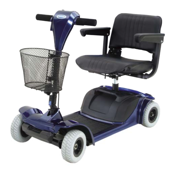
Getting to know your Model 140T/140F Your Model140T/140F scooter from Electric Mobility is a powerful, useful vehicle that offers increased mobility with easy, safe operation. Before using your 140T/140F, use this section to first familiarize yourself with the components, setup, controls, and adjustments to enjoy it safely and successfully. -
Page 13: Initial Setup
ELECTRIC Model 140T/140F Owner’s Manual MOBILITY Initial Setup Prior to using your Model 140T/140F, use the following to initially setup the vehicle for proper use and safe, comfortable operation. Initial setup involves installing the seat and front basket. If the vehicle is delivered with the seat and basket installed, you can skip this section and proceed with how to charge the battery before riding. -
Page 14: Seat Installation
ELECTRIC Model 140T/140F Owner’s Manual MOBILITY Seat Installation To install the seat begin by pulling the locking lever back, located beneath the seat. Insert the seat onto the seat post tube, and release the locking lever to lock seat in position. Turn the seat back and forth slightly allowing the lever to lock into position. -
Page 15: Charging Battery
ELECTRIC Model 140T/140F Owner’s Manual MOBILITY Charging Battery It is recommended to charge your batteries: • Upon initial receipt of your Model 140T/140F • For 6-8 hours (overnight) after extended use during the day • Whenever the battery meter indicator goes into the red area •... -
Page 16: Battery Case Charging Connection
ELECTRIC Model 140T/140F Owner’s Manual MOBILITY 3. Locate Charger connection on top side of Battery Case housing. It is covered by a square, hinged door labeled “Charger.” Battery Case charging connection is shown in Figure 4. 4. Attach the separate AC line cord into the Charger. Connect other end to a 3 prong electrical outlet. -
Page 17: Controls And Adjustments
ELECTRIC Model 140T/140F Owner’s Manual MOBILITY Controls and Adjustments Before driving, it is suggested that you learn about the controls of the scooter and how to perform some initial adjustments to increase safety and improve rider comfort. Operating Controls The vehicle includes the following controls used for BATTERY METER LED STATUS operation. -
Page 18: Led Status Indicator
ELECTRIC Model 140T/140F Owner’s Manual MOBILITY LED Status Indicator - When the scooter is on, and all conditions are normal, the LED will be on. When there is a fault detected that needs attention, the LED will flash. Codes and faults are listed on page 37. Battery Meter —... -
Page 19: Forward/Reverse Engager Levers
ELECTRIC Model 140T/140F Owner’s Manual MOBILITY Forward/Reverse Engager Levers — Selects movement direction and speed of the vehicle. To move forward, push the right lever towards the handle grip. To move in reverse, push the left lever towards the handle grip. Operating speed is proportional to the amount you push each lever. -
Page 20: Adjusting Seat
ELECTRIC Model 140T/140F Owner’s Manual MOBILITY WARNING! DO NOT use armrest as support when transferring on or off the vehicle. Armrests are not designed to support weight of rider when getting on or off the seat. Adjusting Seat SEAT POST BASE SEAT POST TUBE Seat Post Height Adjustments: The seat height can be adjusted manually. - Page 21 ELECTRIC Model 140T/140F Owner’s Manual MOBILITY 3. Position the Adjustable Seat Post Tube to your desired height and align the holes in the Seat Post Base and Seat Post Tube. Insert the Seat Height Locking Pin, making sure the pin is secure. 4.
-
Page 22: Adjusting Handlebar Assembly
ELECTRIC Model 140T/140F Owner’s Manual MOBILITY Adjusting Handlebar Assembly The angle of the handlebar assembly and dash may be adjusted to the individual rider’s preference. Multiple angles are available to reposition the handlebar assembly. The handlebar assembly angle adjustment knob allows you to position the handlebar assembly closer or further away for better access to the controls. -
Page 23: Handlebar Assembly Lock
ELECTRIC Model 140T/140F Owner’s Manual MOBILITY Handlebar Assembly Lock LOCK RELEASED POSITION LOCKED If your 140T/140F is equipped with a handlebar assembly POSITION lock make sure to release the lock by pushing the lock release button. To engage lock push the locking pin down until you hear the pin click into place. -
Page 24: Using The 140T/140F
ELECTRIC Model 140T/140F Owner’s Manual MOBILITY Using the 140T/140F Once you’ve gotten familiar with the 140T/140F components, controls, and have charged the Battery, you can use the following section to use it. This section presents instructions for: • Day-to-Day Use •... -
Page 25: Transferring On Or Off The Vehicle
ELECTRIC Model 140T/140F Owner’s Manual MOBILITY Transferring On or Off the Vehicle Your 140T/140F has been designed to make transferring on and off the vehicle as easy as possible. WARNING! Make sure key is either in the OFF position or removed before transferring ON or OFF the vehicle. -
Page 26: Driving
ELECTRIC Model 140T/140F Owner’s Manual MOBILITY Driving Once seated on your vehicle, driving is as simple as using the Engager Levers to move forward (right lever) or reverse (left lever) and steering in the desired direction. Before driving, however, you should keep in mind the following recommendations. -
Page 27: Inclines
ELECTRIC Model 140T/140F Owner’s Manual MOBILITY Inclines It is recommended that speed be reduced when traveling on (up or down) inclines. Select the slowest speed setting that will still allow the vehicle to climb the incline. NEVER try to turn around on an incline! If vehicle stops on an incline, DO NOT attempt to continue. -
Page 28: Brake Release Lever
ELECTRIC Model 140T/140F Owner’s Manual MOBILITY Brake Release Lever The 140T/140F features a “push mode” to allow it to be pushed by hand . To activate manually, turn the key switch OFF and locate the brake release lever on the right side of the rear cover. The Brake Release Lever is shown in Figure 11. Push lever towards front of vehicle, “PUSH MODE”... -
Page 29: Overload Fuse
ELECTRIC Model 140T/140F Owner’s Manual MOBILITY Overload Fuse If the vehicle is overloaded or is used outside its design parameters it may cause the overload fuse to engage. If this happens the vehicle will stop and beep to alert you. The Overload Fuse in shown in Figure 11. To Reset the Overload Fuse: 1. -
Page 30: Disassembly & Re-Assembly
ELECTRIC Model 140T/140F Owner’s Manual MOBILITY Disassembly & Re-assembly The 140T/140F can be quickly and easily disassembled into four components for storage or transport, then re-assembled when needed. Instructions to take your Model 140T/140F apart and put it back together are presented in this section. FRONT FRAME AND REAR DRIVETRAIN HANDLEBAR ASSEMBLY... -
Page 31: Disassembling Your Model 140T/140F
ELECTRIC Model 140T/140F Owner’s Manual MOBILITY Disassembling Your Model 140T/140F Taking Model 140T/140F apart involves removing the seat and Battery Case, lowering the handlebar assembly, and disconnection the front frame assembly from the rear drivetrain assembly. To Disassemble Model 140T/140F: 1. -
Page 32: Figure 16 - Front Frame Assembly Detachment
ELECTRIC Model 140T/140F Owner’s Manual MOBILITY 5. Lower handlebar assembly onto the frame using the handlebar assembly adjustment knob. 6. Grip seat post with one hand and angle the rear section upwards, as shown in Figure 15. 7. To detach the front frame from the rear, lift front frame off, as shown in Figure 16. -
Page 33: Re-Assembling The Model 140T/140F
ELECTRIC Model 140T/140F Owner’s Manual MOBILITY Re-assembling the Model 140T/140F The Model 140T/140F involves re-attaching the front frame assembly to the rear drivetrain assembly, locking the frame buckle, re-positioning the handlebar assembly and dash for driving operation, and installing the battery case and seat. To Reassemble the Model 140T/140F: 1. - Page 34 ELECTRIC Model 140T/140F Owner’s Manual MOBILITY 3. Grip seat post and lower rear assembly so that front frame and rear drivetrain assembly are reconnected and contacts touch. 4. Fasten the frame buckle and secure the release latch. 5. Position handlebar assembly into preferred driving position. 6.
-
Page 35: Transporting Model 140T/140F
ELECTRIC Model 140T/140F Owner’s Manual MOBILITY Transporting the 140T/140F By Car — To transport your 140T/140F by car, place each of the components into the trunk, being careful not to scratch or mark any of the finished surfaces. If you need assistance lifting weights, consider asking Customer Service Department or your authorized service center about the Power Trunk Lift. - Page 36 ELECTRIC Model 140T/140F Owner’s Manual MOBILITY If traveling outside of the United States, you may require a different charger or an adapter for your present charger. Customer Service or your authorized service center can help you answer these questions and supply you with the charger or adapter you require.
-
Page 37: Maintenance And Servicing
ELECTRIC Model 140T/140F Owner’s Manual MOBILITY Maintenance and Servicing This section presents information to keep your 140T/140F in peak operating condition, including: • Preventative Maintenance • Troubleshooting • Factory Return Procedures Your 140T/140F requires only minimal maintenance and by setting time aside each month for careful inspection and checking items included in this section, you can be assured of a long, useful life of your 140T/140F vehicle. -
Page 38: Preventative Maintenance
ELECTRIC Model 140T/140F Owner’s Manual MOBILITY Preventative Maintenance Performing periodic preventative maintenance on your 140T/140F will ensure long, useful operational life as well as identifying any potential problems that may occur that might effect safe use and operation of the vehicle. Maintenance topics are presented in the following. -
Page 39: Storage
ELECTRIC Model 140T/140F Owner’s Manual MOBILITY Storage DO NOT store your 140T/140F Vehicle in damp conditions. This may affect the electronics if left for very long periods of time. Electronics Servicing of the drive electronics and charger should only be carried out by your local service center. -
Page 40: Battery
ELECTRIC Model 140T/140F Owner’s Manual MOBILITY Battery Keep your battery well charged (see Battery Charging section). Keep battery clean and in a dry frost-proof place. Keep battery contacts clean. To clean brush lightly with fine sand paper. IMPORTANT! It is not possible to predict the life expectancy of your battery. Different workloads will affect battery accordingly. -
Page 41: Troubleshooting Guide
This table is only a guide to aid you in getting your vehicle operating, should you have any problems. If you are unable to get your vehicle operating, call either Electric Mobility Customer Service toll free number located at the front of this manual or your local Authorized Service Center. - Page 42 MOBILITY 3. Cold weather reduces battery life 3. Allow batteries to reach room temperature and then fully recharge 4. Defective charger 4. Contact Electric Mobility or your Authorized Service Center Erratic behavior when engager operated 1. Faulty engager lever 1. Contact Electric Mobility or your Authorized Service Center 2.
-
Page 43: Controller Fault Codes
ELECTRIC Model 140T/140F Owner’s Manual MOBILITY Stiffness in steering 1. Possible grime build up 1. Lubricate bearings 2. Bearings in head tube worn 2. Replace bearings Controller Fault Codes The controller used in Model 140T/140F includes internal diagnostics programming used to identify and troubleshoot faults. -
Page 44: Parts Ordering/Factory Return Procedures
Factory Return Procedures If a part or the entire product is to be returned, call Electric Mobility Customer Service Center to obtain a Return Authorization Number that must be placed on the return package. This number is used to identify the customer, the part and the type of repair. -
Page 45: Specifications
ELECTRIC Model 140T/140F Owner’s Manual MOBILITY Specifications Performance: Model Designation Model 140T/140F Speed up to 3.8 mph Range up to 8 miles Dimensions: Turning Radius 3W - 33.5” ” Length 4W - 47” Width 20” Hill Climbing 8 degrees Height 33”... -
Page 46: Limited Warranty
Limited Warranty Electric Mobility Vehicles warrants the vehicle other than its component battery or batteries, to be free from defects in materials and workmanship for a period of one (1) year from the date of purchase. If, within such warranty period, any such product shall be proven to Electric Mobility Vehicles satisfaction to be defective, such product shall, at option, be repaired or replaced. - Page 47 ELECTRIC Model 140T/140F Owner’s Manual MOBILITY EMC Part: 44000700 • Rev.02 • 04/19/06...
- Page 48 ELECTRIC Model 140T/140F Owner’s Manual MOBILITY EMC Part: 44000700 • Rev.02 • 04/19/06...
- Page 49 ELECTRIC Model 140T/140F Owner’s Manual MOBILITY EMC Part: 44000700 • Rev.02 • 04/19/06...
Need help?
Do you have a question about the EM 140T and is the answer not in the manual?
Questions and answers