Table of Contents
Advertisement
Quick Links
AC5124
AC5124
AC5124
AC5124
2.4 GHz OEM TRANSCEIVER
2.4 GHz OEM TRANSCEIVER
2.4 GHz OEM TRANSCEIVER
2.4 GHz OEM TRANSCEIVER
Specifications Subject to Change
Specifications Subject to Change
Specifications Subject to Change
Specifications Subject to Change
User's Manual
User's Manual
User's Manual
User's Manual
Version 4.4
Version 4.4
Version 4.4
Version 4.4
10981 EICHER DRIVE
10981 EICHER DRIVE
10981 EICHER DRIVE
10981 EICHER DRIVE
LENEXA, KS 66219
LENEXA, KS 66219
LENEXA, KS 66219
LENEXA, KS 66219
(800) 492-2320
(800) 492-2320
(800) 492-2320
(800) 492-2320
www.aerocomm.com
www.aerocomm.com
www.aerocomm.com
www.aerocomm.com
wireless@aerocomm.com
wireless@aerocomm.com
wireless@aerocomm.com
wireless@aerocomm.com
Advertisement
Table of Contents

Related Manuals for AeroComm AC5124


Summary of Contents for AeroComm AC5124
- Page 1 AC5124 AC5124 AC5124 AC5124 2.4 GHz OEM TRANSCEIVER 2.4 GHz OEM TRANSCEIVER 2.4 GHz OEM TRANSCEIVER 2.4 GHz OEM TRANSCEIVER Specifications Subject to Change Specifications Subject to Change Specifications Subject to Change Specifications Subject to Change User’s Manual User’s Manual User’s Manual...
- Page 2 DOCUMENT INFORMATION DOCUMENT INFORMATION DOCUMENT INFORMATION DOCUMENT INFORMATION Copyright Copyright Copyright Copyright Copyright © 2000 A , Inc. All rights reserved. The information contained in this manual and the accompanying Information Information Information Information software programs are copyrighted and all rights are reserved by , Inc.
- Page 3 Version 4.4 11/24/03 – Updated all references to operating temperature from 0°C to 60°C to -40°C to 80°C. All AC5124 products are industrial temperature. Added AT Commands for reading and writing the EEPROM. Updated RSSI plot for new receiver IC.
- Page 4 Portable Portable Portable Mobile Mobile Mobile Mobile AC5124-10 AC5124-200 X-20cm* * See RF Exposure warning on page 6 ** Does not include France and Spain Note: The product approvals above are with antennas specified on page 5. Agency Identification Numbers...
- Page 5 WCR-2400-SMRP Centurion MFB24008RPN Maxrad BMMG24000MSMARP12’ Maxrad BMMG24005MSMARP12’ Maxrad MP24013TMSMARP12 Maxrad MUF24005M174MSMARP12 Maxrad MC2400 Maxrad NZH2400-MMCX (External) AeroComm 10 NZH2400-I (Integrated) AeroComm 11 S131CL-5-RMM-2450S Nearson 12 S181FL-5-RMM-2450S Nearson 13 S191FL-5-RMM-2450S Nearson 14 S151FL-5-RMM-2450S Nearson 15 MLPV1700 Maxrad P=Portable, M=Mobile P=Portable, M=Mobile...
- Page 6 WARNING: The Original Equipment Manufacturer (OEM) must ensure that FCC labeling requirements are met. This includes a clearly visible label on the outside of the OEM enclosure specifying the appropriate AeroComm FCC identifier for this product as well as the FCC Notice above. The FCC identifiers are listed above in the Agency Identifier Numbers section.
-
Page 7: Table Of Contents
TABLE OF CONTENTS TABLE OF CONTENTS TABLE OF CONTENTS TABLE OF CONTENTS TABLES................................. 8 OVERVIEW............................10 AC5124 SPECIFICATIONS ......................11 THEORY OF OPERATION......................12 ..........................12 EFINITIONS ....................13 NTERFACE IGNAL EFINITIONS 1.2.1 Received Signal Strength Indicator (RSSI) ................14 1.1.2... -
Page 8: Tables
Figures Figures Figure 1 - RSSI Voltage vs. Received Signal Strength................14 Figure 2 - API Mode Initialization......................54 Figure 3 – AC5124 with MMCX......................... 55 Figure 4 – AC5124 with Integral Antenna....................56 Tables Tables Tables Tables Table 1 - Interface Signal Definitions ....................... 13 Table 2 - DC Input Voltage Characteristics..................... - Page 9 Table 5 - Transceiver Command Set....................... 27 Table 6 - EEPROM Parameters ........................ 37 Table 7 - BH/BL Selections For Common Baud Rates ................. 43 11/24/03...
-
Page 10: Overview
This document contains information about the hardware and software interface between an AeroComm AC5124 transceiver and an OEM Host. Information includes the theory of operation, system issues, and a basic command set for operational control of the system and transceiver. -
Page 11: Ac5124 Specifications
AC5124-10 Specifications AC5124-10 Specifications AC5124-10 Specifications AC5124-10 Specifications 2. 2. 2. 2. AC5124 Specifications AC5124 Specifications AC5124 Specifications AC5124 Specifications GENERAL GENERAL GENERAL GENERAL Bus Interface Serial (TTL Level Asynchronous) through 40 pin mini connector. AMP P/N 177986-1 Serial Interface Data Rate Programmable to 882 Kbps. -
Page 12: Theory Of Operation
Theory of Operation Theory of Operation The AC5124 has a serial interface that allows the OEM Host to send and receive communications to and from the transceiver. All I/O is 5Vdc TTL level signals except for RSSI, which is an analog output. -
Page 13: Nterface Ignal Efinitions
Logic low (Active Low) will force transceiver into “pseudo” Serial Interface Mode 03 (API). Used for programming the EEPROM. Not recommended for full API Mode operation. See Section 6, Configuring the AC5124 Section 6, Configuring the AC5124 Section 6, Configuring the AC5124 Section 6, Configuring the AC5124. -
Page 14: Received Signal Strength Indicator (Rssi)
Figure 1 shows approximate RSSI performance. There are two versions of receivers used by the AC5124. As of January of 2003 forward, only the New Revision receiver will be shipped. The RSSI pin of the old revision requires the Host to provide a 27kΩ pull-down to ground. No pull-down should be used with the new revision. -
Page 15: In Range (In_Range)
AC5124-10 Specifications AC5124-10 Specifications AC5124-10 Specifications AC5124-10 Specifications 3.2.2 3.2.2 In Range (IN_RANGE) In Range (IN_RANGE) 3.2.2 3.2.2 In Range (IN_RANGE) In Range (IN_RANGE) The IN_RANGE pin will be driven logic low when a Client is in range of a Server on the same Channel and System ID. -
Page 16: Electrical Specifications
AC5124-10 Specifications AC5124-10 Specifications AC5124-10 Specifications AC5124-10 Specifications 3.3 E E E E S S S S LECTRICAL LECTRICAL LECTRICAL LECTRICAL PECIFICATIONS PECIFICATIONS PECIFICATIONS PECIFICATIONS Table Table 2 2 2 2 - DC Input Voltage Characteristics - DC Input Voltage Characteristics... -
Page 17: Serial Interface Modes
Serial Interface Modes Serial Interface Modes The AC5124 provides four Serial Interface Modes for interfacing to the Host, each having protocol parameters that can be programmed for maximum system optimization. Serial Interface Modes 01, 02, and 04 are referred to as Transparent Modes, indicating Host protocol is unnecessary for operation in these modes –... -
Page 18: Serial Interface Mode 03 - Api
ROADCAST OMMUNICATION OMMUNICATION The AC5124 supports both Addressed and Broadcast Modes of communication in all Serial Interface Modes. As necessary, refer to Section 5, API Command Set Section 5, API Command Set Section 5, API Command Set for API command definitions and Section... -
Page 19: Addressed Mode
Auto Destination Auto Destination The AC5124 also supports an addressed mode of communication called Auto Destination. Auto Destination is only for Clients operating in one of the Transparent Modes. To configure a Client for Auto Destination, set bit 7 of EEPROM address 4Fh to a value of 1. With Auto Destination enabled, a Client has the ability to detect any Server with the same Channel and System ID. -
Page 20: Broadcast Mode
AC5124-10 Specifications AC5124-10 Specifications AC5124-10 Specifications AC5124-10 Specifications 4.6.2 4.6.2 Broadcast Mode Broadcast Mode 4.6.2 4.6.2 Broadcast Mode Broadcast Mode 4.6.2.1 4.6.2.1 4.6.2.1 4.6.2.1 Transparent Mode Operation Transparent Mode Operation Transparent Mode Operation Transparent Mode Operation Broadcast communication in a Transparent Mode is intended for use in a point-to-multipoint network (one Server and many Clients). -
Page 21: Rts Handshaking
AC5124-10 Specifications AC5124-10 Specifications AC5124-10 Specifications AC5124-10 Specifications 4.7.2 4.7.2 RTS Handshaking RTS Handshaking 4.7.2 4.7.2 RTS Handshaking RTS Handshaking When the RTS bit is enabled by setting bit 3 of the Serial Interface Mode byte at EEPROM address 4Ah to a value of 1, Pin 27 is used by the Host to keep a transceiver from transmitting data to it. -
Page 22: Api Command Set
Section 6, Configuring the AC5124 Section 6, Configuring the AC5124 Section 6, Configuring the AC5124, as well as control and monitor network communications. Section 6, Configuring the AC5124 As mentioned in Section 4.3, Serial Interface Mode 03 – API Section 4.3, Serial Interface Mode 03 –... -
Page 23: System
AC5124-10 Specifications AC5124-10 Specifications AC5124-10 Specifications AC5124-10 Specifications 5.1 S S S S C C C C S S S S YSTEM YSTEM YSTEM YSTEM OMMAND OMMAND OMMAND OMMAND The System Commands allow the OEM to initialize the system and perform general system analysis. -
Page 24: Control
Diagnostic Result command before issuing any additional commands. Refer to Section 6, Configuring the AC5124 Section 6, Configuring the AC5124 Section 6, Configuring the AC5124 for the list of configurable EEPROM Section 6, Configuring the AC5124 parameters. Sub-command (Counts as 1 Byte in the... -
Page 25: Standby
AC5124-10 Specifications AC5124-10 Specifications AC5124-10 Specifications AC5124-10 Specifications 5.1.4 5.1.4 Standby Standby 5.1.4 5.1.4 Standby Standby The Host issues the following commands to enable Sleep Walk Mode for Clients and Deep Sleep Mode for Servers. See Section 6.1.13.3, Power Down Modes Section 6.1.13.3, Power Down Modes for detailed information on these modes. -
Page 26: Update Eeprom Checksum
AC5124-10 Specifications AC5124-10 Specifications AC5124-10 Specifications AC5124-10 Specifications Status Reply Example Status Reply Example Status Reply Example Status Reply Example Name Name Name Name Type Type Type Type 0 Active Transceivers 0 Active Transceivers 0 Active Transceivers 0 Active Transceivers... -
Page 27: Acknowledge
AC5124-10 Specifications AC5124-10 Specifications AC5124-10 Specifications AC5124-10 Specifications 5.1.10 5.1.10 Acknowledge Acknowledge 5.1.10 5.1.10 Acknowledge Acknowledge A transceiver issues this command in response to some of the Host commands indicating a positive response. The Acknowledge Acknowledge Acknowledge Acknowledge consists of the Host command sequence with a zero length, unless otherwise noted. -
Page 28: Send Data
(6) Bytes for the IEEE 802.3 destination address, or FF FF FF FF FF FF for broadcast packets • (6) Bytes for the IEEE 802.3 source address These unique IEEE addresses are provided by AeroComm and stored in EEPROM addresses 28h – 2Dh. 5.2.3 5.2.3 Send Data Complete Send Data Complete 5.2.3... -
Page 29: Received Data
Range Refresh parameter at EEPROM address 32h. The OEM should allow for some hysterisis so the Host isn’t flooded with these commands in a fringe coverage area. AeroComm has established a default value of 5 seconds through extensive testing. This command includes the IEEE 802.3 Server Address. -
Page 30: At Command Set
AT Commands are valid for modes 1, 2, and 4 of the AC5124. Whether in mode 1, 2, or 4, this command must be sent to the radio as a complete packet. Any characters before or after this command that become appended to this string to form a larger packet will cause the packet to be interpreted as a packet to send over the RF and not an AT command. -
Page 31: Enter Command Mode
AC5124-10 Specifications AC5124-10 Specifications AC5124-10 Specifications AC5124-10 Specifications 6.2.1 6.2.1 Enter Command Mode Enter Command Mode 6.2.1 6.2.1 Enter Command Mode Enter Command Mode Prior to sending any other AT command, the radio must be sent the Enter Command Mode command by the OEM Host. -
Page 32: Power-On Reset Command
AC5124-10 Specifications AC5124-10 Specifications AC5124-10 Specifications AC5124-10 Specifications 6.2.3 6.2.3 Power-on Reset Command Power-on Reset Command 6.2.3 6.2.3 Power-on Reset Command Power-on Reset Command To force the radio to perform a Power-on Reset, the Power-on Reset command should be sent to the radio by the OEM Host. -
Page 33: Write Iram Byte
AC5124-10 Specifications AC5124-10 Specifications AC5124-10 Specifications AC5124-10 Specifications 6.2.5 6.2.5 6.2.5 6.2.5 Write IRAM Byte Write IRAM Byte Write IRAM Byte Write IRAM Byte IRAM Writes are performed one byte at a time. To write a byte of IRAM, the OEM Host should issue the following command to the radio: ATSXX=YY↵... -
Page 34: Read Eeprom Byte
AC5124-10 Specifications AC5124-10 Specifications AC5124-10 Specifications AC5124-10 Specifications 6.2.6 6.2.6 Read EEPROM Byte Read EEPROM Byte 6.2.6 6.2.6 Read EEPROM Byte Read EEPROM Byte EEPROM Reads are performed one byte at a time. To read a byte of EEPROM, the OEM Host should issue the following command to the radio: ATWXX?↵... -
Page 35: Write Eeprom Byte
AC5124-10 Specifications AC5124-10 Specifications AC5124-10 Specifications AC5124-10 Specifications 6.2.7 6.2.7 Write EEPROM Byte Write EEPROM Byte 6.2.7 6.2.7 Write EEPROM Byte Write EEPROM Byte EEPROM Writes are performed one byte at a time. To write a byte of EEPROM, the OEM Host should... -
Page 36: Configuring The Ac5124
Table 6 – EEPROM Parameters, contains the many configurable parameters that are stored in the EEPROM on a transceiver. These parameters are read by the AeroComm firmware on power-up or when a reset is executed. This section provides the definitions, valid values and use for each of these parameters. - Page 37 AC5124-10 Specifications AC5124-10 Specifications AC5124-10 Specifications AC5124-10 Specifications Table Table Table Table 6 6 6 6 - EEPROM Parameters - EEPROM Parameters - EEPROM Parameters - EEPROM Parameters EEPROM EEPROM EEPROM EEPROM Length Length Length Length Default Default Default Default...
- Page 38 AC5124-10 Specifications AC5124-10 Specifications AC5124-10 Specifications AC5124-10 Specifications EEPROM EEPROM EEPROM EEPROM Length Length Length Length Default Default Default Default Parameter Parameter Description Description Parameter Parameter Description Description Address Address Address Address (Bytes) (Bytes) (Bytes) (Bytes) (Hex) (Hex) (Hex) (Hex) Serial Interface 01h –...
-
Page 39: Software Version Number
Software Version Number Software Version Number EEPROM Address: 1Dh Length: 8 Bytes Default: Depends on version Can be read by the OEM for AeroComm firmware version information. The OEM must not change this information. 7.1.2 7.1.2 7.1.2 7.1.2 IEEE MAC Address... -
Page 40: Channel
AC5124-10 Specifications AC5124-10 Specifications AC5124-10 Specifications AC5124-10 Specifications 7.1.3 7.1.3 Channel Channel 7.1.3 7.1.3 Channel Channel EEPROM Address: 2Eh Length: 1 Byte Default: 00h Range: 00h – Provides 77 unique and non-interfering pseudorandom hopping sequences or Channels. This allows the OEM to configure up to 77 independent, co-located data networks. The combination of the Channel and System ID must be unique to each network of transceivers to establish communication. -
Page 41: Range Refresh
Range command. This parameter is useful when operating in a fringe condition to minimize the In In In In Range Range Range Range and Out of Range Out of Range commands that may flood the Host. AeroComm has established a default Range Range Out of Range Out of Range value of 5 seconds through extensive testing. -
Page 42: System Id
AC5124-10 Specifications AC5124-10 Specifications AC5124-10 Specifications AC5124-10 Specifications 7.1.8 7.1.8 System ID System ID 7.1.8 7.1.8 System ID System ID EEPROM Address: 34h Length: 8 Bytes Default: 00 00 00 00 00 00 00 01 Range: 00 00 00 00 00 00 00 00 to FF FF FF FF FF FF FF FF The System ID is used in conjunction with the Channel and serves as a password to maintain secure transfers of data. -
Page 43: Baud High (Bh) And Baud Low (Bl)
AC5124-10 Specifications AC5124-10 Specifications AC5124-10 Specifications AC5124-10 Specifications 7.1.10 7.1.10 Baud High (BH) and Baud Low (BL) Baud High (BH) and Baud Low (BL) 7.1.10 7.1.10 Baud High (BH) and Baud Low (BL) Baud High (BH) and Baud Low (BL) -
Page 44: Random Back-Off
AC5124-10 Specifications AC5124-10 Specifications AC5124-10 Specifications AC5124-10 Specifications 7.1.12 7.1.12 Random Back-Off Random Back-Off 7.1.12 7.1.12 Random Back-Off Random Back-Off EEPROM Address: 45h Length: 1 Byte Default: 03h The Carrier Sense Multiple Access (CSMA) protocol does not keep time slots for each registered Clients like some protocols. - Page 45 AC5124-10 Specifications AC5124-10 Specifications AC5124-10 Specifications AC5124-10 Specifications 7.1.13.2 7.1.13.2 7.1.13.2 7.1.13.2 Parity Mode Parity Mode Parity Mode Parity Mode EEPROM Address: 4Ah, bit 5 Length: 1 Bit Default: 0 Range: 0 or 1 Setting this bit to a value of 1 will enable Parity (9 bit transmit) mode. In this mode, 9 bit bytes can be sent over the RF.
- Page 46 AC5124-10 Specifications AC5124-10 Specifications AC5124-10 Specifications AC5124-10 Specifications 7.1.13.4.1 7.1.13.4.1 S S S S W W W W M M M M (C (C (C (C O O O O ) ) ) ) 7.1.13.4.1 7.1.13.4.1 LEEP LEEP LEEP LEEP...
-
Page 47: Transmit Mode
AC5124-10 Specifications AC5124-10 Specifications AC5124-10 Specifications AC5124-10 Specifications 7.1.13.4.2 7.1.13.4.2 D D D D S S S S M M M M (S (S (S (S O O O O ) ) ) ) 7.1.13.4.2 7.1.13.4.2 LEEP LEEP LEEP LEEP... -
Page 48: Read Switches
AC5124-10 Specifications AC5124-10 Specifications AC5124-10 Specifications AC5124-10 Specifications 7.1.16 7.1.16 Read Switches Read Switches 7.1.16 7.1.16 Read Switches Read Switches EEPROM Address: 4Ch, bit 1 Length: 1 Bit Default: 0 Range: 0 or 1 The Read Switches bit is useful for systems that need to change Channels or Server/Client Mode during operation. - Page 49 Setting this bit to a value of 1 reduces the number of RF receive buffers to one. Otherwise, there are eight RF receive buffers on the AC5124, each large enough to store the maximum packet size of 2 KBytes. This allows the AC5124 to act as a RAM buffer in many applications and actually improve system throughput as opposed to wired communications.
-
Page 50: Interface Timeout
AC5124-10 Specifications AC5124-10 Specifications AC5124-10 Specifications AC5124-10 Specifications 7.1.17 7.1.17 Interface Timeout Interface Timeout 7.1.17 7.1.17 Interface Timeout Interface Timeout EEPROM Address: 4Dh Length: 1 Byte Default: 00h Range: 00h - FFh This parameter applies only to Transparent Mode 01. This parameter specifies the amount of time between bytes that a transceiver will wait before transmitting the data packet. - Page 51 AC5124-10 Specifications AC5124-10 Specifications AC5124-10 Specifications AC5124-10 Specifications 7.1.19.1 7.1.19.1 7.1.19.1 7.1.19.1 Turbo Mode Turbo Mode Turbo Mode Turbo Mode EEPROM Address: 4Fh, bit 1 Length: 1 Bit Default: 0 Range: 0 or 1 If bit 1 is set to a value of 0, a transceiver will operate in CSMA mode, allowing random back-off for collision avoidance.
-
Page 52: Destination Ieee Mac Address
Default: 0 Range: 0 or 1 The AC5124 supports an addressed mode of communication called Auto Destination. This mode is only for Clients operating in one of the Transparent Modes. To configure a Client for Auto Destination, set this bit to a value of 1. With Auto Destination enabled, a Client has the ability to detect any Server with the same Channel and System ID. -
Page 53: Initializing The Ac5124 Transceiver
Send Data Send Data command is invoked. The AC5124 transceivers are designed to be single threaded, meaning that for every command issued, there is a reply command that indicates the completion of the command issued. There can be no command interleaving. -
Page 54: Figure 2 - Api Mode Initialization
AC5124-10 Specifications AC5124-10 Specifications AC5124-10 Specifications AC5124-10 Specifications The figure below provides an example of the initialization sequence for both Clients and Servers following the configuration of EEPROM parameters. This occurs only in API Mode. Figure Figure 2 2 2 2 - API Mode Initialization... -
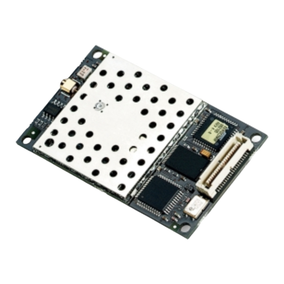
Page 55: Mechanical Overview
9. 9. 9. 9. Mechanical Overview Mechanical Overview Mechanical Overview Mechanical Overview The AC5124 measures 1.65”W x 2.65”L. Critical parameters are as follows: • J1 J1 J1 – 40 pin OEM interface connector (AMP P/N 177986-1) mates with AMP P/N 177985-1 •... -
Page 56: Figure 4 - Ac5124 With Integral Antenna
AC5124-10 Specifications AC5124-10 Specifications AC5124-10 Specifications AC5124-10 Specifications Figure Figure Figure Figure 4 4 4 4 – AC5124 with Integral Antenna – AC5124 with Integral Antenna – AC5124 with Integral Antenna – AC5124 with Integral Antenna 11/24/03... -
Page 57: Ordering Information
RODUCT UMBERS UMBERS AC5124-10: AC5124-10: AC5124-10: AC5124-10: AC5124 with 10mW output power, interface data rates to 882 Kbps, MMCX antenna connector AC5124-10A: AC5124-10A: AC5124 with 10mW output power, interface data rates to 882 Kbps, integral AC5124-10A: AC5124-10A: AeroComm NZH microstrip dipole antenna...
Need help?
Do you have a question about the AC5124 and is the answer not in the manual?
Questions and answers