
Related Manuals for AeroComm PKLR2400S


Summary of Contents for AeroComm PKLR2400S
- Page 1 PKLR2400S 10mW OEM TRANSCEIVER Specifications Subject to Change Datasheet Version 3.9 13256 W. 98 STREET LENEXA, KS 66215 (800) 492-2320 www.aerocomm.com wireless@aerocomm.com Arrow.com. Downloaded from...
- Page 2 Changed Baud Low Default from F7 to F1 Updated Section 6 – API Command Set with examples & corrections Added pin notations on Figure 1 - Mechanical Overview of PKLR2400S Version 3.9 9/25/00 – Corrected DTR pin number from 33 to 34, pin 33 is NC Changed pin 24 from Reserved to NC Remove Note from the CTS timing diagram in Sections 3.3.1 &...
- Page 3 DOCUMENT INFORMATION This material is preliminary Information furnished by A in this specification is believed to be accurate. Devices sold by A are covered by the warranty and patent indemnification provisions appearing in its Terms of Sale only. A makes no warranty, express, statutory, and implied or by description, regarding the information set forth herein.
- Page 4 EUR/EN Portable Mobile Fixed PKLR2400S-10 Note: The product approval above is with antennas specified below. FCC Notice WARNING: This device complies with Part 15 of the FCC Rules. Operation is subject to the following two conditions: (1) This device may not cause harmful interference and (2) This device must accept any interference received, including interference that may cause undesired operation.
- Page 5 WARNING: The Original Equipment Manufacturer (OEM) must ensure that FCC labeling requirements are met. This includes a clearly visible label on the outside of the OEM enclosure specifying the AeroComm FCC identifier, KQL-PKLR2400, for this product as well as the FCC Notice above.
-
Page 6: Table Of Contents
RANSPARENT IXED ENGTH IMEOUT ....................16 ERIAL NTERFACE UFFER ....................16 NITIALIZATION EQUENCE CONFIGURING THE PKLR2400S ..................18 EEPROM P ..................18 YSTEM ARAMETERS 5.1.1 Product Identifier String/Version Information ............18 5.1.2 IEEE Assigned MAC Address..................18 5.1.3 Channel Number...................... 19 5.1.4... - Page 7 Send Data* ......................35 6.2.3 Send Data Complete* ....................35 6.2.4 Received Data*......................36 6.2.5 In Range*......................... 36 6.2.6 Out of Range*......................36 PKLR2400S T ................. 37 NITIALIZING THE RANSCEIVER MECHANICAL OVERVIEW ....................38 ORDERING INFORMATION....................39 ....................39 RODUCT UMBERS ..................39...
-
Page 8: Overview
This document contains information about the hardware and software interface between an AeroComm PKLR2400S transceiver and an OEM Host. Information includes the theory of operation, system issues, and a basic command set for operational control of the system and transceiver. -
Page 9: Pklr2400S Specifications
PKLR2400S-10 Specifications 2. PKLR2400S Specifications GENERAL Bus Interface Serial (TTL Level Asynchronous) or Parallel through 40 pin mini connector. AMP P/N 177986-1 Interface Data Rate Serial Programmable to 882Kbps. PC rates to 57.6 Kbps Parallel 4 Mbps Compliance Certifiable under: US –... -
Page 10: Theory Of Operation
3. Theory of Operation The PKLR2400S has a serial interface that allows the OEM Host to send and receive communications to and from the transceiver. All I/O is 5Vdc TTL level signals except for RSSI, which is an analog output. All outputs are weakly pulled logic High (20 k –... -
Page 11: Interface Signal Definitions
PKLR2400S-10 Specifications 3.2 I NTERFACE IGNAL EFINITIONS The following pinout is for the 40-pin mini-connector, J1 (AMP P/N 177986-1). I/O direction is with regard to the transceiver. Table 1. Transceiver Interface Signal Definitions Type Signal Name Function Signal Ground PKTMODE... -
Page 12: Host
PKLR2400S-10 Specifications 3.3 H OFTWARE ARDWARE NTERFACE EFINITION 3.3.1 Clear To Send (CTS) CTS requires a minimum delay of 40µs between (1) and (2) after the end of each data packet. Delay for reply command CTS from transceiver TXD – LSB first... -
Page 13: Received Signal Strength Indicator
PKLR2400S-10 Specifications 3.3.5 Received Signal Strength Indicator The Received Signal Strength Indicator is used by the Host to determine the instantaneous signal strength at the receiver. The Host must calibrate RSSI without a signal being presented to the receiver. Figure 1 shows approximate RSSI performance. -
Page 14: Eeprom Write Enable (Wr_Ena)
RESET. Failure to do so may result in corruption of important EEPROM data. 4. Serial Interface Modes The PKLR2400S provides four different Serial Interface Modes that can be configured for maximum system optimization. These Modes include three Transparent modes and one API mode. The transceiver-to- transceiver protocol is identical for all three Transparent Modes. -
Page 15: Serial Interface Mode 03 - Api
PKLR2400S-10 Specifications 4.3 S 03 – API ERIAL NTERFACE Mode 03 specifies API Mode. In this mode, the OEM has control of the transceiver command set detailed in Section 6.2. Packets are transmitted upon completion of the Send Data* command. -
Page 16: Serial Interface Buffer
When operating in the three Transparent Serial Interface Modes, the initialization sequence is managed by the AeroComm protocol. In Range* commands are not issued and there are no acknowledgements from the transceiver on data delivery unless the OEM protocol has built-in acknowledgements. - Page 17 Checksum Note: All serial data must be transmitted LSB first. Note: The PKLR2400S transceivers are designed to be single threaded, meaning that for every command issued, there is a reply command that indicates the completion of the command issued. There can be no command interleaving.
-
Page 18: Configuring The Pklr2400S
There are many configurable parameters that are stored in the EEPROM on the transceiver. These parameters are read by the AeroComm firmware on power-up or when a reset is executed. If the OEM is writing to the EEPROM, they must use the Write EEPROM Command and enable pin 37 (WR_ENA). These parameters and their respective EEPROM address locations are highlighted in this section. -
Page 19: Channel Number
PKLR2400S-10 Specifications 5.1.3 Channel Number EEPROM Address: 2Eh Size: 1 Byte Default: 00h Range: 00h – Provides 77 unique and non-interfering pseudorandom hopping sequences or Channels. This allows the OEM to configure up-to 77 independent, co-located data networks. It is highly recommended that the OEM change the channel to a number other than 00h. -
Page 20: Baud High (Bh) And Baud Low (Bl)
PKLR2400S-10 Specifications 5.1.6 Baud High (BH) and Baud Low (BL) EEPROM Address: 40h and 41h respectively Size: 1 Byte Default: FFh for BH and F1h for BL Range: 00h FFh for BH and BL – Baud High (BH) and Baud Low (BL) are used to configure the serial interface data rate between the transceiver and its Host. -
Page 21: Protocol Eeprom Parameters
PKLR2400S-10 Specifications 5.2 P EEPROM P ROTOCOL ARAMETERS The Protocol EEPROM Parameters are related to the Serial Interface Modes. A summary of the required EEPROM settings is illustrated in Section 5.3, EEPROM Parameter Summary. Note: These parameters can only be changed when the API Serial Interface Mode 03 is active. -
Page 22: Transmit Data Link Attempts
Server beacon. This parameter is very useful when operating in a fringe condition to minimize the In Range* and Out-of-Range* commands that may flood the Host. AeroComm has established a default value of 5 seconds through extensive testing. -
Page 23: End Character Definition
PKLR2400S-10 Specifications 5.2.4 End Character Definition EEPROM Address: 3Eh Size: 1 Byte Default: FFh Range: 00h – This parameter is used only when the transceiver is operating in Serial Interface Mode 02. This parameter is ignored when the transceiver is operating in all other modes. The value specified by the OEM will indicate the last character in a data packet. -
Page 24: Serial Interface/Power Down Modes
PKLR2400S-10 Specifications 5.2.6 Serial Interface/Power Down Modes EEPROM Address: 4Ah Size: 1 Byte Default: 01h Range: 01h – There are four Serial Interface Modes for the OEM transceiver including one API Mode and three Transparent Modes. All modes are differentiated by the definition of when data will be transmitted by the transceiver. - Page 25 PKLR2400S-10 Specifications 5.2.6.1 Power Down Modes The PKLR2400S Power Down Modes include a Sleep Walk and Deep Sleep mode. Sleep Walk is for Clients only and Deep Sleep is for Servers only. If bit 7 of the Serial Interface/Power Down Mode Byte is set, the Client enters into Sleep Walk mode. This applies to ALL modes (01-04).
-
Page 26: Destination Address Control
PKLR2400S-10 Specifications 5.2.6.2 Modem If bit 6 of the Serial Interface/Power Down Mode Byte is set, the transceiver uses all of the modem lines (DCD, DSR, DTR, RI, RTS, and CTS). If this bit is set, then the bit 3 (RTS bit) must be set for the transceivers to operate properly. -
Page 27: Broadcast Attempts
PKLR2400S-10 Specifications 5.2.9 Broadcast Attempts EEPROM Address: 4Eh Size: 1 Byte Default: 04h Range: 01h – The Broadcast Attempts parameter applies only to the Broadcast Modes for all four Serial Interface Modes and specifies the number of times the RF interface will broadcast each packet. The receiving transceiver will discard duplicate packets. -
Page 28: Eeprom Parameter Summary
PKLR2400S-10 Specifications 5.3 EEPROM P ARAMETER UMMARY EEPROM Parameters Serial Interface Modes Address Description Serial Interface Mode Transmit Attempts 01-FF 01-FF 01-FF 01-FF 01-FF 01-FF Receive Mode Range Refresh 01-FF 01-FF End Char Definition 00-FF 00-FF Fixed Pkt Length-HB 01-07... -
Page 29: Api Command Set (Serial Interface Mode 03 Only)
PKLR2400S-10 Specifications 6. API Command Set (Serial Interface Mode 03 Only) The basic command set consists of several commands for the Host and transceiver. The command set can be used ONLY when the transceiver is in API Serial Interface Mode 03, determined by EEPROM address location 4Ah. -
Page 30: Reset
PKLR2400S-10 Specifications 6.1.1 Reset* The Host issues this command to the transceiver. This command provides a software reset to the transceiver, initializing the code at the same location as a hardware reset. This command must be followed by an RF Enable* command. -
Page 31: Diagnostic Result
PKLR2400S-10 Specifications 6.1.3 Diagnostic Result* The transceiver issues this command to the Host in response to a Control* command. Sub result (Counts as 1 Byte in the Description Length) 02h* Read EEPROM 08h* NOP. Returns 6 Bytes (87 02 00 08 00 8D) 09h* Write EEPROM status. -
Page 32: Status Reply
PKLR2400S-10 Specifications 6.1.6 Status Reply* The transceiver issues this command to the Host in response to a Status Request* command. The parameters pertain to the RF Data Link Layer and provide cumulative totals. The statistics and their sizes are shown below:... -
Page 33: Update Eeprom Checksum
PKLR2400S-10 Specifications Status Reply Example Name Type 0 Active Transceivers 2 Active Transceivers Transceiver Time Time Counter 1 Byte – TL 1 Byte – TL 1 Byte – TM 1 Byte – TM 1 Byte – TH 1 Byte – TH... -
Page 34: Acknowledge
PKLR2400S-10 Specifications 6.1.10 Acknowledge* The transceiver issues this command in response to some of the Host issued commands indicating a positive response. The Acknowledge* consists of the Host command sequence with a zero length. 6.2 T RANSCEIVER OMMAND UMMARY The Transceiver Commands allow the OEM to control the flow of data into and out of the transceiver as well as initialization of the transceiver in API Serial Interface Mode 03. -
Page 35: Send Data
(6) Bytes for the IEEE 802.3 standard destination address • (6) Bytes for the IEEE 802.3 standard source address These unique IEEE addresses are provided by AeroComm and stored in EEPROM location 28h. Note: The Length must include the IEEE 802.3 Header. 6.2.3 Send Data Complete* The transceiver issues this command upon completion of the data transmission process, as indicated by a RF-layer Acknowledgment from the destination transceiver. -
Page 36: Received Data
In-Range, Out of Range Refresh parameter at EEPROM address location 32h. The OEM should allow for some hysterisis so the Host isn’t flooded with these commands in a fringe coverage area. AeroComm has established a default value of 5 seconds through extensive testing. -
Page 37: Initializing The Pklr2400S Transceiver
PKLR2400S-10 Specifications 6.3 I PKLR2400S T NITIALIZING THE RANSCEIVER The following diagram is an example of the initialization sequence for both the Clients and Servers following configuration of the EEPROM parameters. This occurs only in the API Serial Interface Mode 03. -
Page 38: Mechanical Overview
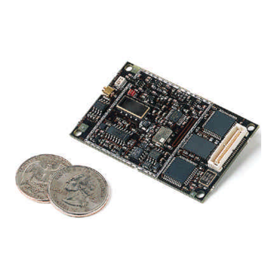
PKLR2400S-10 Specifications 7. Mechanical Overview The PKLR2400S measures 1.65” x 2.65”. Critical parameters are as follows: • J1 – 40 pin OEM interface connector (AMP P/N 177986-1) mates with AMP P/N 177985-1 • J2 – High frequency MMCX style antenna connector (Telegartner P/N J0134A0081) mates with any manufacturer’s MMCX plug... -
Page 39: Ordering Information
8. Ordering Information 8.1 P RODUCT UMBERS PKLR2400S-10, PKLR2400S with 10mW output power, interface data rates to 882Kbps, MMCX antenna connector PKLR2400S-10A, PKLR2400S with 10mW output power, interface data rates to 882Kbps, integrated AeroComm NZH microstrip dipole antenna (Available Q4/00) 8.2 D...
Need help?
Do you have a question about the PKLR2400S and is the answer not in the manual?
Questions and answers