Table of Contents
Advertisement
Quick Links
Advertisement
Table of Contents

Related Manuals for AeroComm AC4790


Summary of Contents for AeroComm AC4790
- Page 1 AC4790 900 MHz OEM TRANSCEIVERS Specifications Subject to Change User’s Manual Version 1.3 11160 THOMPSON AVENUE LENEXA, KS 66219 (800) 492-2320 www.aerocomm.com wireless@aerocomm.com Downloaded from Elcodis.com electronic components distributor...
- Page 2 Limited Warranty, Disclaimer, Limitation of Liability For a period of one (1) year from the date of purchase by the OEM customer, AeroComm warrants the OEM transceiver against defects in materials and workmanship. AeroComm will not honor this warranty (and this warranty will be automatically void) if there has been any (1) tampering, signs of tampering;...
- Page 3 DOCUMENT INFORMATION Revision Description Version 1.0 2/21/2005 – Initial Release Version Version 1.1 3/4/2005 – Updated Session Count Truth Table in Section 4. Version 1.2 4/26/2005 – Updated Transmit Mode Section. Version 1.3 3/27/2006 – Corrected API Send Data Complete. Added Australian Channels. Added 1x1 documentation.
-
Page 4: Table Of Contents
Test (pin 12)............................20 RSSI (pin 13)............................21 UP_Reset (pin 15)..........................21 Command/Data (pin 17)........................21 AD In (pin 18)............................21 Session Status (pin 20) ........................21 CONFIGURING THE AC4790.........................22 AC4790 AT C ............................22 OMMANDS Enter AT Command Mode........................23 Exit AT Command Mode ........................23 (CC C )..................23... - Page 5 APPENDIX IV – API TIMING DIAGRAMS ......................47 LIST OF FIGURES Table 1 - Pin Definitions ............................8 Table 2 - Input Voltage Characteristics (AC4790-1000 & AC4790-1x1) .............9 Table 3 - Output Voltage Characteristics (All).....................9 Table 4 - Session Count Truth Table ........................11 Table 5 - Supported Serial Formats ........................14...
-
Page 6: Overview
Advanced configuration available using AT commands OVERVIEW The AC4790 is a member of AeroComm’s ConnexRF OEM transceiver family. The AC4790 is a cost effective, high performance, frequency hopping spread spectrum transceiver; designed for integration into OEM systems operating under FCC part 15.247 regulations for the 900 MHz ISM band. -
Page 7: Specifications
AC4790-200: 3.3 – 5.5V, ±50mV ripple AC4790-1000*: Pin 10: 3.3 – 5.5V ±50mV ripple Pin 11: 3.3 ±3%, ±100mV ripple * Pins 10 and 11 may be tied together, provided the supply voltage never falls below 3.3 V and is capable of supplying 1.5 A of current. -
Page 8: Pin Definitions
The I/O direction is with respect to the transceiver. All outputs are 3.3VDC levels and inputs are 5VDC TTL (with the exception of AC4790-1x1 and AC4790-1000 transceivers which have 3.3V inputs). All inputs are weakly pulled High and may be left floating during normal operation (with the exceptions listed for the AC4790-1x1). -
Page 9: Electrical Specifications
ELECTRICAL SPECIFICATIONS Table 2 - Input Voltage Characteristics (AC4790-1000 & AC4790-1x1) AC47901x1 / AC4790-1000M AC4790-200X High High High High Signal Name Unit Min. Max. Min. Max. Min. Max. Min. Max. RS485A/B 2.31 0.99 2.31 0.99 2.31 0.99 Test 2.31 0.99 2.31... -
Page 10: Theory Of Operation
Modes of Operation The AC4790 has three different operating modes: Transmit Mode, Receive Mode and Command mode. When not in Transmit or Command Mode the radio will be in Receive Mode ready to receive data and awaiting a sync pulse from another transceiver. - Page 11 Receive Mode If the transceiver detects a sync pulse while in Receive Mode, it will join the Session and start receiving data. While in Receive Mode, subsequent data/RF Acknowledge of up to 128 bytes can be received every hop. When a transceiver is in Session, its’ Session Count is decremented by one every hop. When the Session Count reaches zero, the transceiver exits the Session.
-
Page 12: Api Control
Command Mode A radio will enter Command Mode when data is received over the serial interface from the OEM Host and either the Command/Data pin (pin 17) is logic Low or the received data contains the “AT+++” (Enter AT Command Mode) command. - Page 13 thereby eliminating the need for extensive programming on the OEM Host side. This ability of the protocol makes it ideal for any legacy system. API Transmit Packet API Transmit Packet is enabled when bit-1 of the API Control byte is enabled. The OEM Host should use the following format to transmit a packet over the RF.
-
Page 14: Serial Interface
Serial Interface In order for an OEM Host and a transceiver to communicate over the serial interface they need to have the same serial data rate. Refer to the following sections to ensure OEM Host Data Rate matches the Serial Interface Baud Rate. OEM Host Data Rate The OEM Host Data Rate is the rate with which the Data... -
Page 15: Flow Control
UPLEX When Half Duplex communication is chosen, the AC4790 will send a packet out over the RF whenever it can. This can cause packets sent by multiple transceivers at the same time to collide with each other over the RF. To prevent this, Full Duplex communication can be chosen. -
Page 16: Interface Timeout /Rf Packet Size
YSTEM HROUGHPUT When operating as shown in the Table 7, RF Status Half Duplex Full Duplex an AC4790 transceiver is capable of Throughput (bps) Throughput (bps) each way achieving the listed throughput. Radio not in continuous Session 12.5k However, in the presence of interference... -
Page 17: Random Back Off
Table 8 - RF Channel Number Settings Channel Set RF Channel Number Range Frequency Details and Countries (0x40) Regulatory Requirements 0 (AC4790-1x1, 0x00 – 0x0F 902 – 928MHz (26 hop bins) US/Canada AC4790-200) 1 (AC4790-1x1, 0x10 – 0x2F 902 – 928MHz (50 hop bins) -
Page 18: Max Power
OWER Max Power provides a means for controlling the RF output power of the AC4790. Output power and current consumption can vary by as much as ±10% per transceiver for a particular Max Power setting. Contact AeroComm for assistance in adjusting Max Power. The following graphs show current consumption versus output power. - Page 19 Figure 7 - Current vs. Output Power for AC4790-1x1 Output Current EEPROM Power (mA) Setting (mW) 0x 60 12.75 0x 50 7.15 74.5 0x 08 5.82 73.87 0x 07 4.52 73.42 0x 06 3.29 73.03 0x 05 1.33 72.2 0x 03 Quick Tip: The max power is set during Production and may vary slightly from one transceiver to another.
-
Page 20: Hardware Interface
Hardware Interface Below is a description of all hardware pins used to control the AC4790. transceiver before the buffer can be emptied, data loss GIn (Generic Inputs 0 and 1) (pins 4 will occur. The transceiver prevents this loss by... -
Page 21: Rssi (Pin 13)
UP_Reset provides a direct connection to the reset pin to-Digital converter hardware. Reading of this pin on the AC4790 microprocessor and is used to force a can be performed locally using the Read ADC soft reset. For a valid reset, reset must be asserted... -
Page 22: Configuring The Ac4790
AC4790 AT C OMMANDS The AT Command mode implemented in the AC4790 creates a virtual version of the Command/Data pin. The “Enter AT Command Mode” Command asserts this virtual pin Low (to signify Command Mode) and the “Exit AT Command Mode”... -
Page 23: Enter At Command Mode
OMMANDS OMMAND The AC4790 transceiver contains static memory that holds many of the parameters that control the transceiver operation. Using the “CC” command set allows many of these parameters to be changed during system operation. Because the memory these commands affect is static, when the transceiver is reset, these parameters will revert back to the settings stored in the EEPROM. -
Page 24: Command Quick Reference
Command Quick Reference Command Name Command (All Bytes in Hex) Return (All Bytes in Hex) AT Enter 0x41 0x54 0x2B 0x2B 0x2B 0x0D 0xCC 0x43 0x4F 0x4D Command Mode Exit AT Command 0xCC 0x41 0x54 0x4F 0x0D 0xCC 0x44 0x41 0x54 Mode Firmware Version... -
Page 25: Firmware Revision Request
Firmware Revision Request Write Destination Address The OEM Host issues this command to request the The OEM Host issues this command to the transceiver firmware of the transceiver. to change the Destination Address. Command: 0xCC 0x00 0x00 Note: Only the three Least Significant Bytes of the MAC Address are used for packet delivery. -
Page 26: Write Api Control
Write API Control Read Radio Table The OEM Host issues this command to the transceiver The OEM Host issues this command to read the Radio to write the API Control byte. Table that resides on the transceiver. The Radio Table stores information for up to the last 8 transceivers that Command: 0xCC 0x17 sent it a packet. -
Page 27: Read Adc
Read ADC Command: 0xCC 0x8E Data1 Number of bytes returned: 2 The OEM Host issues this command to read any of the Response: 0xCC Data1 three onboard 10 bit A/D converters. Because the RF Parameter Range: is still active in on-the-fly Command Mode, the Data1 = 0x00 –... -
Page 28: Eeprom Byte Write
EEPROM Byte Write Upon receiving this command, a transceiver will Command: CCh C1h Data1 Data2 Data write the data byte to the address specified but Number of bytes returned: 4+ will not echo it back to the OEM Host until the Response: CCh Data1 Data2 Data EEPROM write cycle is complete. -
Page 29: Eeprom Parameters
1 – 0xFE = (value * 1.6us) + 12us Channel Number 0x40 0x00 – AC4790-1x1: 0x00 Set 0 = 0x00 – 0x0F (US/Canada): AC4790-1x1/200 0x2F AC4790-200: 0x00 Set 1 = 0x10 – 0x2F (US/Canada): AC4790-1x1/1000 AC4790-1000: 0x10 Set 3 = 0x30 – 0x37 (US/Canada): AC4790-1x1-200... - Page 30 EEPROM Length Parameter Range Default Description Address (Bytes) Interface Timeout 0x58 0x02 – 0x04 Specifies a byte gap timeout, used in conjunction with RF 0xFF Packet Size to determine, when a packet coming over the interface is complete (0.5ms per increment). RF Packet Size 0x5B 0x01 –...
- Page 31 EEPROM Length Parameter Range Default Description Address (Bytes) Random Back- 0xC3 0x0 – 0x00 The Random amount of time a transceiver waits when a 0xFF collision occurs, before resending the packet again. 0x00 = Disable Random Backoff 0x01 = Wait 1-2 packet times, then retry 0x03 = Wait 1-4 packet times, then retry 0x07 = Wait 1-8 packet times, then retry 0x0F = Wait 1-16 packet times, then retry...
-
Page 32: Dimensions
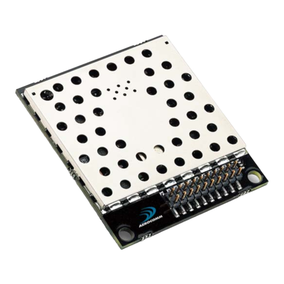
Critical parameters are as follows: Interface Connector – 20 pin OEM interface connector (Molex 87759-0030, mates with Samtec SMM-110-02-S-D) MMCX Jack – Antenna connector (Johnson Components 135-3711-822) Figure 10 - AC4790 (with MMCX connector) Mechanical Downloaded from Elcodis.com electronic components distributor... - Page 33 Figure 11 - AC4790 (with integral gigaAnt antenna on top) Mechanical Downloaded from Elcodis.com electronic components distributor...
- Page 34 Figure 12 - AC4790 (with integral gigaAnt antenna on bottom) Mechanical Downloaded from Elcodis.com electronic components distributor...
- Page 35 Figure 13 - AC4790-1x1 Mechanical Downloaded from Elcodis.com electronic components distributor...
- Page 36 Figure 14 - AC4790 1x1 PCB Considerations Downloaded from Elcodis.com electronic components distributor...
-
Page 37: Ordering Information
All the above part numbers can be ordered as a development kit by prefacing the part number with “SDK-“. As an example, part number AC4790-200A can be ordered as a development kit using the following part number: SDK-AC4790-200A. All Developer Kits include (2) transceivers, (2) Serial Adapter Boards, (2) 6VDC unregulated power supplies, (2) Serial cables, (2) USB cables, (2) S467FL-6-RMM-915S dipole antennas with 6”... -
Page 38: Agency Compliancy Information
NTENNA The following antennas are approved for operation with the AC4790 as identified. The OEM is free to choose another vendor’s antenna of equal or lesser gain and similar type as an antenna appearing in the table and still maintain compliance. -
Page 39: Fcc / Industry Canada (Ic) Requirements For Modular Approval
2.5cm of the antenna even if the equipment is designated as being greater than 2.5cm). The AC4790 is not agency approved for portable applications. The OEM is required to have additional testing performed to receive this classification. -
Page 40: Warnings Required In Oem Manuals
Agency Compliancy Information Warnings Required in OEM Manuals RF Exposure for Warning for Mobile Equipment WARNING: This equipment has been approved for mobile applications where the equipment should be used at distances greater than 20cm from the human body (with the exception of hands, wrists, feet and ankles). -
Page 41: Appendix I - Power Supply Application Note
Application Note Here is a simple switching power supply that provides enough current to easily power any Aerocomm OEM module. It utilizes low cost, off the shelf components that fit into a small area. This supply has an input voltage range of +6 volts to +18 volts and will output +3.4 volts at 1.5 amps. - Page 42 Appendix I – Power Supply Application Note Downloaded from Elcodis.com electronic components distributor...
-
Page 43: Appendix Ii - Converting From 5V Levels To 3.3V Levels
Converting from 5V to 3.3V The AC4790-1000M and the AC4790-1x1 have 3.3 V input levels. However, this can cause problems if a designer wants to use an older 5V circuit in the same design. Some of the most common voltage conversion methods are described below. -
Page 44: Appendix Iii - Api
I. Daisy Chain / Repeater With the use of API commands a daisy chain or repeater can be implemented easily with the AC4790. Radio A would send a packet to radio B which would store the data in its buffer. When the session between A & B has ended, radio B initiates a session with radio C which in turn stores the data until the current session has ended. - Page 45 Appendix III – API seed range. 81h 01h 08h 04h FFh FFh FFh AAh Radios A, B, C, & D receive the packet and send it to the OEM Host in the following format: 81h 01h XXh XX h 01h 23h 45h AAh Advanced For a more intelligent network, a Time Division Multiple Access (TDMA) system could be implemented.
- Page 46 Appendix III – API Radio A receives the packet which tells it to begin transmitting its’ information. Radio A sends the information back to the master unit and the session expires after 8 hops. Master switches to radio B using TX API: 81h 01h 08h 04h 12h 34h ABh AAh Radio B receives the packet which tells it to begin transmitting its’...
-
Page 47: Appendix Iv - Api Timing Diagrams
Appendix IV – API Timing Diagrams Appendix IV – API Timing Diagrams Session Count = 8, Retries = 3 Session Count = 3, Retries = 3 Downloaded from Elcodis.com electronic components distributor... - Page 48 Appendix IV – API Timing Diagrams Session Count = 2, Retries = 2 Session Count = 1, Retries = 1 The timing diagrams above show the radios performance with varying Session Count and Retry values. Data was sent from Radio A – B – C – D and then from D – C – B – A. Downloaded from Elcodis.com electronic components distributor...
Need help?
Do you have a question about the AC4790 and is the answer not in the manual?
Questions and answers