Table of Contents
Advertisement
Quick Links
Advertisement
Table of Contents

Related Manuals for AeroComm CL4490PRO


Summary of Contents for AeroComm CL4490PRO
- Page 1 E R S I O N...
- Page 2 Limited Warranty, Disclaimer, Limitation of Liability For a period of one (1) year from the date of purchase by the OEM customer, AeroComm warrants the OEM transceiver against defects in materials and workmanship. AeroComm will not honor this warranty (and this warranty will be automatically void) if there has been any (1) tampering, signs of tampering;...
- Page 3 D O C U M E N T I N F O R M A T I O N Revision Description Version 1.0 11/15/06 - Initial Release Version 1 - 8 0 0 - 4 9 2 - 2 3 2 0 w w w .
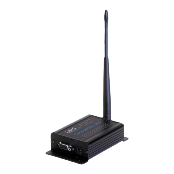
- Page 4 C L 4 4 9 0 - P R O R F T R A N S C E I V E R The CL4490-PRO transceiver is a Frequency-Hopping Spread Spectrum (FHSS) radio designed for license- free operation in the 900 MHz ISM band. The radio sustains a standard asynchronous serial data stream between two or more radios out of the box.
- Page 5 C H A P T E R 1 - C L 4 4 9 0 - P R O R F T R A N S C E I V E R This document contains information about the hardware and software interface between an AeroComm CL4490-PRO transceiver and an OEM Host.
-
Page 6: Specifications
S P E C I F I C A T I O N S T A B L E 1 : C L 4 4 9 0 - P R O S P E C I F I C A T I O N S I N T E R F A C E Serial Interface Connector DB-9 Female... -
Page 7: Serial Interface
S E R I A L I N T E R F A C E The CL4490 supports RS232, RS485, and RS422 protocols. Aerocomm wireless solutions are not subject to the cabling restrictions for distance, and either interface is available when ordering. - Page 8 C H A P T E R 3 - S E R I A L I N T E R F A C E R S 2 3 2 RS232 is a single-ended data transmission protocol. The RS232 signals are represented by voltage levels with respect to a system common (power/logic ground).
- Page 9 C H A P T E R 3 - S E R I A L I N T E R F A C E R S 4 8 5 ( 2 - W I R E ) The RS-485 interface uses a Differential Data Transmission that can help nullify the effects of ground shifts and induced noise signals that can appear as common mode voltages on a network.
- Page 10 C H A P T E R 3 - S E R I A L I N T E R F A C E R S 4 8 5 ( 4 - W I R E ) A N D R S 4 2 2 F i g u r e 5 : R S 4 8 5 F u l l D u p l e x w i t h T e r m i n a t i o n D I P S w i t c h S e t t i n g s With Termination Without Termination...
- Page 11 C H A P T E R 3 - S E R I A L I N T E R F A C E apart from the data itself on separate wires. Note: CTS is always enabled by default. RS-485 Interface does not support Hardware flow control.
-
Page 12: Theory Of Operation
Each network should consist of only one Server and there should never be two servers on the same RF Channel number in the same coverage area as the interference between the two servers will severely hinder RF communications. For those applications requiring collocated servers, Aerocomm recommends using the Sync-to-Channel feature which is further explained in the Sync-to-Channel Appendix. - Page 13 C H A P T E R 4 - T H E O R Y O F O P E R A T I O N R E C E I V E M O D E When a transceiver is not in Transmit or Command mode, it will be in Receive Mode listening for data. While in Receive Mode, subsequent data of up to 80 bytes can be received every hop (20 ms).
- Page 14 C H A P T E R 4 - T H E O R Y O F O P E R A T I O N N E T W O R K T O P O L O G I E S Topology refers to the shape of a network, or the network's layout.
-
Page 15: C O N N E X L I N K S E T T I N G S
The RF baud rate is fixed at 76.8 Kbps and is independent of the Interface Baud Rate. The default baud rate setting is 57600 bps unless the units have been pre-configured by AeroComm. The Interface Baud Rate setting of the CL4490-PRO must match the Baud Rate setting of its host device. - Page 16 C H A P T E R 5 - C O N N E X L I N K S E T T I N G S 10) MAC Address: A unique 6 Byte, IEEE 802.3 Ethernet address assigned by AeroComm to each CL4490-PRO.
- Page 17 Note: The Show Defaults button can be used to display the default Radio settings. DESIGN TIP The Aerocomm Configuration utility automatically programs the mode (point-to-point or point- to-multipoint) based on the radio’s current settings: If the Destination Address field is set to any value other than FF FF FF FF FF FF, the radio will send data only to the radio whose MAC matches that specified in the Destination Address field (point-to-point).
-
Page 18: Configuration Utility
For additional details regarding the radio’s operation and advanced configuration commands, users may refer to the AC4490 OEM module user’s manual. The manual can be found on the Aerocomm Tools & Literature CD or on our website http://www.aerocomm.com. - Page 19 C H A P T E R 6 - C O N F I G U R A T I O N U T I L I T Y P C S E T T I N G S P A G E The PC Settings page is shown below, as it will appear the first time the program is run.
- Page 20 A B O U T B U T T O N The About button can be pressed to determine the revision number of the software and the contact information for Aerocomm. Please include the software revision number in any correspondence with Technical Support.
- Page 21 C H A P T E R 6 - C O N F I G U R A T I O N U T I L I T Y There are five sections on the Configure page; Radio Interface, Radio RF, Radio Features, Radio Other, and Info Center.
- Page 22 C H A P T E R 6 - C O N F I G U R A T I O N U T I L I T Y W R I T E R A D I O B U T T O N After making changes to the controls on the Configure page, the Write Radio button can be pressed to save those changes to the radio EEPROM.
- Page 23 C H A P T E R 6 - C O N F I G U R A T I O N U T I L I T Y An EEPROM can be saved to a file using the Save to File button. This allows for the current state of the EEPROM to be restored at a later time.
- Page 24 C H A P T E R 6 - C O N F I G U R A T I O N U T I L I T Y S E N D B U T T O N This button sends the data in the textbox out the selected port(s). The current user’s Windows username is also sent over the RF with the data.
- Page 25 C H A P T E R 6 - C O N F I G U R A T I O N U T I L I T Y R A N G E T E S T P A G E The Range Test page allows packets of data to be sent between two radios and reports the numbers of successes and errors.
- Page 26 C H A P T E R 6 - C O N F I G U R A T I O N U T I L I T Y If using two PCs for the test, the software run on both sides should have the second COM port disabled on the Settings page.
-
Page 27: Side View
M E C H A N I C A L F i g u r e 7 : C L 4 4 9 0 - P R O M e c h a n i c a l 1.170 Ante 0.536 0.060 0.000...
Need help?
Do you have a question about the CL4490PRO and is the answer not in the manual?
Questions and answers