
Subscribe to Our Youtube Channel
Related Manuals for Alto DPA 2500


Summary of Contents for Alto DPA 2500
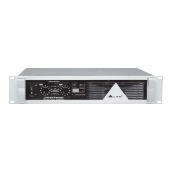
- Page 1 User's Manual 40 BIT ENHANCED DPA 2500/4000 STEREO POWER AMPLIFIER www.altoproaudio.com Version 1.0 September 2004 English...
- Page 2 the recommended fuse type as indicated in this SAFETY RELATED SYMBOLS manual. Do not short-circuit the fuse holder. Before replacing the fuse, make sure that the product is CAUTION OFF and disconnected from the AC outlet. RISK OF ELECTRIC SHOCK DO NOT OPEN Protective Ground This symbol, wherever used, alerts you to the pre-...
- Page 3 LTO AUDIO TEAM's endeavors. LTO AUDIO TEAM, music and audio are much more than a job, they are a passion and an obsession! We have been designing professional audio products for a long time in cooperation with many of the world's major brands.
-
Page 4: Table Of Contents
TABLE OF CONTENTS 1. INTRODUCTION.............................4 2. FEATURES.............................4 3. CONTROL ELEMENTS..........................4 3.1 The Front Panel 3.2 The Rear Panel 4. GETTING STARTED..........................6 4.1 Preset Selection 4.2 Edit Menu 4.3 Channel Selection 4.4 Comm Selection: 4.5 SIG/LIMITER LED 5. REMOTE CONTROL ..........................7 5.1 How to set the DPA's ID number 5.2 Connection to the PC 5.3 First Steps with the PC Editor... -
Page 5: Introduction
1. INTRODUCTION LTO DPA2500/4000 40 Bit DSP Stereo Amplifier is a high power, low profile, professional Power Amplifier with advanced features and great reliability. In fact, the amplifier functions far beyond a traditional power amplifier, it is also a versatile effect processor. You can set the input and output audio configuration through recalling one of the presets included in the internal memory or PC editor software. - Page 6 6. Level Control for Channels 1&2 These two controls are used to adjust output level of channel 1 and channel 2 respectively. 7. UP/DOWN Key This key is used to move inside the menus or to modify the parameter's value. 8.
-
Page 7: Getting Started
17. Fan The fan can accelerate the flow of air to lower the temperature inside unit.The inside temperature determines the fan speed which controls the inside air flowing speed. 18. RS485 IN The function of the RS485 IN is opposite to RS85 OUT. It allows incoming communication between a DPA2500 /4000 stereo amplifier and PC or another DPA2500/4000 stereo amplifier. -
Page 8: Channel Selection
- Hum Cancel (ON/OFF) Select "EDIT" using SELECT key. Then select "HUM CANCEL" using UP/DOWN keys, both the "HUM CANCEL" and "EDIT" indicators will light Press "ENTER" to set Hum Cancel function ON or OFF. Note: the HUM CANCEL indicator will be lighting all the time if you set this function ON, and it effects only on selected channels. -
Page 9: Connection To The Pc
5.2 Connection to the PC Connect the First DPA to the PC's RS232 serial port, using a 9-pin female plug connected to the RS232 socket on the rear panel of unit. Connect RS485 IN of the Second DPA to the First DPA 's RS485 OUT socket, in this way, you can connect up 32 DPA units for a same PC. -
Page 10: Edit Mode (Password Protection)
2>. The PC Editor should now load. A welcome screen will appear. This closes after 5 seconds (or click on it). Select NEW from the FILE menu. A window will open showing several different model names, because the same software is used for some of our pro audio models. Select DPA amp and click OK. You will then be presented with 2 options NEW UNIT and NETWORK SCAN. -
Page 11: Help File
5.5 Help File The HELP file accessible from within the PC Editor will be updated as necessary. Since software updates after the printing of this manual may affect the instructions provided here, please check the Help File for any later remarks. 5.6 Introduction to the PC Editor When you launch the editor on your PC, you will see the opening screen following (later software versions may differ). -
Page 12: Parameter Menus Description
6. PARAMETER MENUS DESCRIPTION - HUM CANCEL: allows the modification of the dynamic NOTCH filter parameters. The graph included shows the filter response curve. - NOISE GATE: allows the modification of the noise gate parameters. The graph included shows the filter curve. - MULTICOMP: allows the modification of the multiband compressor parameters. -
Page 13: Connections
8. CONNECTIONS The following diagrams show the schemes of the recommended cables and some connection examples referred to various system configurations. Inputs A & B, RS485 IN GROUND BALANCED XLR-M HOT (+) COLD ( ) Inputs A & B SLEEVE GROUND BALANCED JACK RING... -
Page 14: Application
9. APPLICATION Total two optional modes: Please see following diagram for connecting the power amplifier into your audio system. 9.1 Stereo Mode In this mode, channel 1 and channel 2 operate independently (just as traditional input into channel 1 can be out- put from channel 1 only, similarly, the signal input into channel 2 can be output from channel 2 only. - Page 15 You can also operate the paralleled mode via outside wiring, so the signal input from channel 1 or 2 will beo- tuput from both channel 1 and channel 2 simultaneously. The volume of channel 1 or channel 2 can be contr olled separately.
- Page 16 Input Connector Input Connector Balanced Channel 1 INPUT POWER OUTPUTS Apparaten skall anslutas till jordat uttag nar den ansluts till ett natverk INPUT INPUT INPUT INPUT BRIDGE RS485 IN TIP/PIN 2 TIP/PIN 2 BREAKER RING/PIN 3 RING/PIN 3 OUTPUT1 SLEEVE/PIN 1 SLEEVE/PIN 1 BRIDGE MONO...
-
Page 17: Bridge Mode
9.2 Bridge Mode In this mode, the signal input into channel 1 will be output from the bridged end, on the other hand, the output level control of channel 2 should be turn down to smallest (turn the volume control at counterclockwise). Only the volume control of channel 1 is used to control the volume of whole system. -
Page 18: Technical Specifications
10. TECHNICAL SPECIFICATIONS MODEL DPA2500/4000 40 Bit DSP Enhanced Stereo Amplifier 20Hz 20KHz@0.1% THD, Stereo Mode 8 ohms per channel(EIAJ) 460W / 625W 4 ohms per channel(EIAJ) 830W / 1000W Bridge Mono Mode 8 ohms, 1KHz, 0.1%THD 1400W / 2000W Distortion (SMPTE-IM) <0.05% Frequency Response... -
Page 19: Warranty
11. WARRANTY 1. WARRANTY REGISTRATION CARD To obtain Warranty Service, the buyer should first fill out and return the enclosed Warranty Registration Card within 10 days of the Purchase Date. All the information presented in this Warranty Registration Card gives the manufacturer a better understanding of the sales status, so as to purport a more effective and efficient after-sales warranty service. - Page 20 SEKAKU ELECTRON INDUSTRY (H.K.) CO. LTD. No.1, Lane 17, Sec. 2, Han Shi West Road, Taichung, 401 TAIWAN http://www.altoproaudio.com Tel:886-4-22313737 email: alto@altoproaudio.com Fax:886-4-22346757 All rights reserved to ALTO. All features and content might be changed without prior notice. Any photocopy, translation, or reproduction of part of this manual without written permission is forbidden.
Need help?
Do you have a question about the DPA 2500 and is the answer not in the manual?
Questions and answers