
Related Manuals for Alto D1


Summary of Contents for Alto D1
- Page 1 OWNER'S MANUAL D1/D2/D3/D4 PROFESSIONAL POWER AMPLIFIERS www.altoproaudio.com Version 1.3 SEPTEMBER 2007 English...
-
Page 2: Important Safety Instruction
IMPORTANT SAFETY INSTRUCTION CAUTION WARNING To reduce the risk of electric shock RISK OF ELECTRIC SHOCK and fire, do not expose this equipment DO NOT OPEN to moisture or rain. TO REDUCE THE RISK OF ELECTRIC SHOCK PLEASE DO NOT REMOVE THE COVER OR Dispose of this product should THE BACK PANEL OF THIS EQUIPMENT. -
Page 3: Table Of Contents
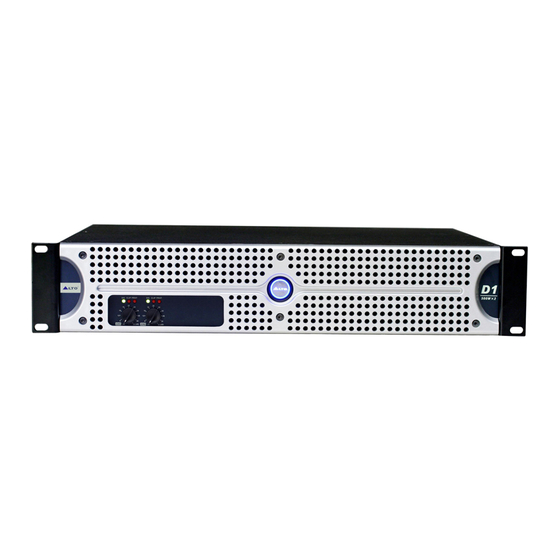
Thank you for expressing your confidence in L TO products by purchasing one or more of our D series power amplifiers. The D range includes D1, D2, D3 and D4. There are 2 channels for the D1/D3, and 4 channels for D2/D4. All models are rugged, 2 rack-unit amplifiers fan-cooled. - Page 4 500W 2 S G CLIP PROT S G CL P PROT ( B) (dB) 500W 4 S G CLIP PROT S G CL P PROT SIG CL P PROT IG CLIP PROT ( B) 750W 2 S G CL P PROT SIG CL P PROT (dB) 750W 4...
-
Page 5: Stereo Mode
HOOK STEREO MODE In this mode 2 independent channels are sent to 2 separate speakers. HOOK PARALLEL MODE One mono signal is input to CH A or CH B of the D series amplifier and then output to 2 separate speakers. Each speaker volume can be set separately. -
Page 6: Bridge Mode
HOOK STEREO BIAMP This application is only for D1 or D3. For the D2 or D4, it has four channels so only use one amplifier . The Main Mix signal is routed into an electronic crossover . CH A drives... -
Page 7: Control Elements
3. CONTROL ELEMENTS Front Panel: 1 POWER SWITCH & INDICATOR LED It powers the D amplifier ON and OFF . When the D amplifier is turned on the power switch illuminates blue. 2 SIGNAL LED This LED will light up green when the signal at the output is at least -20 dB. 3 CLIP LED This LED will flash when distortion reaches a level of 0.5%, Turn the relative GAIN control down so that the CLIP LEDs only flash occasionally. - Page 8 3. CONTROL ELEMENTS Rear Panel: 7 CIRCUIT BREAKER This is an electronic fuse for protecting the unit from possible damage. When the unit is overloaded or the temperature inside the unit is too high, this push-type button will spring out and disconnect the power supply. Push the Breaker to restore normal working conditions.
- Page 9 3. CONTROL ELEMENTS 12 LOW FREQUENCY FILTER This Filter rolls off audio signals below 30Hz. In this way bass performance will be improved, because the subsonic motion of the cone will be cut out and more power is made available to the woofer in the audible range of frequencies. If you want our view: Keep the Filter ON most of the time unless you are filtering the signal before the input of the amplifier .
-
Page 10: Operation
In this mode, channel A and channel B operate independently (as a conventional stereo amplifier). The channel A input signal will be output from the channel A output connectors, and the channel B input signal will be output from the channel B output connectors. For D1/D3(2-CHANNEL) CHANNEL 1 PUSH PUSH... - Page 11 NOTE: since you are not using the channel B input you can use this socket to "daisy-chain" the signal to another amplifier. For D1/D3(2-CHANNEL) NO USING PUSH PUSH...
- Page 12 8 ohms or greater. In Bridge Mode you will combine the power of both channels into one speaker. You will have available massive amount of power so check carefully the power handling of your speaker before operation. For D1/D3(2-CHANNEL) NO USING PUSH MODE...
-
Page 13: Block Diagram
5. BLOCK DIAGRAM... -
Page 14: Technical Specification
6. TECHNICAL SPECIFICATIONS POWER SPECIFICATIONS 4 Ohms 8 Ohms 4 Ohms 8 Ohms ELECTRICAL SPECIFICATIONS INPUT SENSITIVITY INPUT IMPEDANCE FREQUENCY RESPONSE VOLTAGE GAIN DISTORTION(SMPTE-1M) S/N RATIO GENERAL SPECIFICATIONS PROTECTIONS CONTROLS SIGNAL: green LED CLIP: red LED INDICATORS POWER: blue LED PROTECTION: red LED INPUT : balanced combo CONNECTORS... -
Page 15: Warranty
6. WARRANTY 1. WARRANTY REGISTRATION CARD To obtain Warranty Service, the buyer should first fill out and return the enclosed Warranty Registration Card within 10 days of the Purchase Date. All the information presented in this Warranty Registration Card gives the manufacturer a better understanding of the sales status, so as to provide a more effective and efficient after-sales warranty service. - Page 16 NO. 1, Lane 17, Sec. 2, Han Shi West Road, Taichung 40151, Taiwan http://www.altoproaudio.com Tel: 886-4-22313737 email: alto@altoproaudio.com Fax: 886-4-22346757 All rights reserved to ALTO. All features and content might be changed without prior notice. Any photocopy, translation, or reproduction of part of this manual without written permission is forbidden. Copyright 2007 Seikaku Group NF02695-1.3...
Need help?
Do you have a question about the D1 and is the answer not in the manual?
Questions and answers