Table of Contents
Advertisement
SERVICE MANUAL
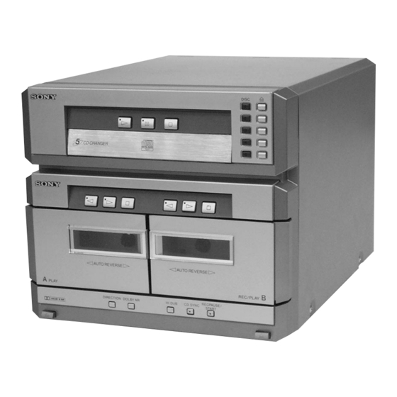
HTC-NX1 is the CD player and Tape
Deck section in MHC-NX1/NX3AV.
Dolby noise reduction manufactured under license
from Dolby Laboratories Licensing Corporation.
"DOLBY" and the double-D symbol a are trade-
marks of Dolby Laboratories Licensing Corporation.
MICROFILM
HTC-NX1
Model Name Using Similar Mechanism
CD Mechanism Type
CD
Section
Base Unit Name Type
Optical Pick-up Name
Model Name Using Similar Mechanism
Tape Deck
Section
Tape Transport Mechanism Type
SPECIFICATIONS
MINI Hi-Fi COMPONENT SYSTEM
US Model
Canadian Model
AEP Model
UK Model
E Model
Australian Model
Tourist Model
HCD-MD555
CDM53D-K1BD33
BU-K1BD33
KSM-213BFN-C2NP
HCD-GRX7
TCM-230AWR2
Advertisement
Table of Contents

Related Manuals for Sony HTC-NX1


Summary of Contents for Sony HTC-NX1
- Page 1 Canadian Model AEP Model UK Model E Model Australian Model Tourist Model HTC-NX1 is the CD player and Tape Deck section in MHC-NX1/NX3AV. Dolby noise reduction manufactured under license Model Name Using Similar Mechanism HCD-MD555 from Dolby Laboratories Licensing Corporation.
-
Page 2: Table Of Contents
SUR LES DIAGRAMMES SCHÉMATIQUES ET LA LISTE DES PIÈCES SONT CRITIQUES POUR LA SÉCURITÉ DE FONCTIONNEMENT. NE REMPLACER CES COM- POSANTS QUE PAR DES PIÈCES SONY DONT LES NUMÉROS SONT DONNÉS DANS CE MANUEL OU DANS LES SUPPLÉMENTS PUBLIÉS PAR SONY. - Page 3 POWER SUPPLY DURING SERVICING Connection: Connector cable (17P) of • As this set has not own power supply, it does not operate inde- attachment to power feed jig pendently. Therefore, during servicing, connect it to the Pre- Main amplifier and Tuner Unit (STR-NX1/NX3) of MHC-NX1/ Relay connector jig NX3AV.
- Page 4 OPTICAL PICK-UP CLEANING 1 Remove the case. (Refer to disassembly page 8) 2 four screws (BVTP M2.6) 3 Open the magnet ass’y. 4 Cleaning the Note 1: In cleaning the lens, do not apply an excessive force. optical pick-up. As the optical pick-up is vulnerable, application of excessive force could damage the lens holder.
-
Page 5: General
SECTION 2 GENERAL • LOCATION OF CONTROLS – Front Panel – 1 2 3 1 G (CD) button and indicator 2 S (CD) button and indicator 3 s (CD) button 4 DISC1 to 5 buttons and indicators 5 A (DISC1 to 5) buttons and indicators 6 g (DECK A) button and indicator 7 G (DECK A) button and indicator 8 s (DECK A) button... -
Page 6: Disassembly
SECTION 3 DISASSEMBLY Note: Follow the disassembly procedure in the numerical order given. CASE 1 screw (BVTP3 × 10) 3 Remove the case 2 two screws in the arrow A (case 3 TP2) direction. 2 two screws (case 3 TP2) FRONT PANEL SECTION 3 two screws (BVTP3 ×... - Page 7 CD MECHANISM DECK SECTION (CDM53D-K1BD33) 4 Remove the CD mechanism deck section (CDM53D-K1BD33) in 3 four screws the arrow A direction. (BVTP3 × 10) to fitting base (guide) ass’y, bracket (chassis) and magnet ass’y (page 9) 1 flat cable (17 core) (12 cm) (CN112) 2 connector (CN713)
- Page 8 CD BASE UNIT (BU-K1BD33) 4 CD base unit (BU-K1BD33) 3 compression spring 2 compression spring (black) (silver) 1 two screws 1 two screws (PTPWH M2.6) (PTPWH M2.6) MAIN BOARD 4 Remove the MAIN board in the arrow A direction. 2 two screws (BVTP3 ×...
- Page 9 FITTING BASE (GUIDE) ASS’Y, BRACKET (CHASSIS) AND MAGNET ASS’Y 7 four screws (BVTP M2.6) 5 bracket (chassis) 2 four screws (BVTP M2.6) 4 screw (BVTP M2.6) 6 connector (CN710) 8 magnet ass’y from CD mechanism deck section 4 screw (CDM53D-K1BD3) (BVTP M2.6) (page 7) 3 fitting base...
- Page 10 CHASSIS (MOLD B) SECTION, STOCKER SECTION AND SLIDER (SELECTION) Note: In mounting the parts, refer to page 11 and 12. 6 two screws (PTPWH M2.6) 5 stocker section 7 slider (selection) 8 washer 9 compression 1 three screws spring pulley (LD) (BVTP M2.6) 4 two step screws...
- Page 11 SLIDER (SELECTION) INSTALLATION 6 two screws (PTPWH M2.6) 2 gear (chuking) rotary encoder 5 washer 4 compression spring 7 Insert the slider (selection) into the portion A. Align with the slot of rotary encoder. portion A 3 convex portion of slider (selection) gear (chuking) 1 rotary encoder...
- Page 12 CHASSIS (MOLD B) SECTION INSTALLATION 3 three screws (BVTP M2.6) 2 Insert the gear (eject) 1 Insert the portion A of under the gear (LD chassis (mold B) section deceleration). portion A into the portion B of slider (selection). gear (LD deceleration) portion B of slider (selection)
-
Page 13: Test Mode
SECTION 4 TEST MODE [LED All Lit, Key Check Mode] Procedure: 1. Press the button to turn the power ON. 2. Press three buttons of (DECK B), (DISC 1), and [DISC 5] simultaneously. 3. LEDs are all turned on. Press the (CD) button, and the key check mode is activated. -
Page 14: Mechanical Adjustments
SECTION 5 SECTION 6 MECHANICAL ADJUSTMENTS ELECTRICAL ADJUSTMENTS Precaution TAPE DECK SECTION 0 dB=0.775 V 1. Clean the following parts with a denatured alcohol-moistened swab: 1. Demagnetize the record/playback head with a head demagne- record/playback heads pinch rollers tizer. erase head rubber belts 2. - Page 15 DECK B 2. Turn the adjustment screw and check output peaks. If the peaks Tape Speed Adjustment do not match for L-CH and R-CH, turn the adjustment screw so that outputs match within 1dB of peak. • Execute only if connected to the STR-NX1/NX3 Mode: Playback test tape AUDIO OUT jack...
- Page 16 DECK B REC Bias Adjustment Specified value: AUDIO OUT jack PB level: 47.2 to 53.0 mV (–24.3 to –23.3 dB) Procedure: 1. Mode: Record Adjustment Location: MAIN board AUDIO IN jack – MAIN BOARD (Conductor Side) – 1) 315 Hz ...
-
Page 17: Cd Section
RF LEVEL CHECK CD SECTION Note: oscilloscope 1. CD Block is basically designed to operate without adjustment. There- fore, check each item in order given. BD board 2. Use YEDS-18 disc (3-702-101-01) unless otherwise indicated. 3. Use an oscilloscope with more than 10 MΩ impedance. TP (RF) 4. - Page 18 Connecting points: – BD BOARD (Side B) – – MAIN BOARD (Conductor Side) – IC101 IC102 (VC) (AGCCON) (FEO) SL101 (RF) (ADJ) IC101 (GND) (TEO) TP (VC) TP (FEI)
-
Page 19: Diagrams
SECTION 7 DIAGRAMS 7-1. NOTE FOR PRINTED WIRING BOARDS AND SCHEMATIC DIAGRAMS • Circuit Boards Location (In addition to this, the necessary note is printed in each block) CLAMP MOTOR board Note on Printed Wiring Board: Note on Schematic Diagram: SENSOR 2 board •... -
Page 20: Printed Wiring Board - Bd Board
HTC-NX1 7-2. PRINTED WIRING BOARD – BD Board – • See page 19 for Circuit Boards Location. (GND) (Page 27) • Semiconductor • Semiconductor Location Location (Side A) (Side B) Ref. No. Location Ref. No. Location Q101 IC101 IC102 IC103... -
Page 21: Schematic Diagram - Bd Board
HTC-NX1 7-3. SCHEMATIC DIAGRAM – BD Board – • See page 32 for Waveforms. • See page 32 for IC Block Diagrams. (Page 29) • Voltages and waveforms are dc with respect to ground under no-signal conditions. no mark : CD PLAY The components identified by mark 0 or dotted Les composants identifiés par une marque 0 sont... -
Page 22: Printed Wiring Boards - Cd Motor/Sensor Section
HTC-NX1 7-4. PRINTED WIRING BOARDS – CD MOTOR/SENSOR Section – • See page 19 for Circuit Boards Location. TO OUT SW BOARD TO IN SW BOARD TO CONNECTOR BOARD TO SENSOR BOARD (Page 27) TO CLAMP TO INT/ MOTOR COUNT SW... -
Page 23: Schematic Diagram Cd Motor/Sensor Section
HTC-NX1 • Voltages are dc with respect to ground under no-signal conditions. no mark : CD PLAY 7-5. SCHEMATIC DIAGRAM – CD MOTOR/SENSOR Section – • See page 33 for IC Block Diagram. (Page 29) (Page 29) -
Page 24: Printed Wiring Board - Audio Board
HTC-NX1 7-6. PRINTED WIRING BOARD – AUDIO Board – • See page 19 for Circuit Boards Location. (Page 27) -
Page 25: Schematic Diagram - Audio Board
HTC-NX1 7-7. SCHEMATIC DIAGRAM – AUDIO Board – • See page 33 for IC Block Diagram. PB EQ AMP (PLAYBACK) (DECK A) PB LEVEL (L) (DECK A) PB LEVEL (R) (DECK A) PB EQ AMP (DECK B) PB LEVEL (L) (DECK B) A +7.5V... -
Page 26: Printed Wiring Board - Leaf Sw Board
HTC-NX1 7-8. PRINTED WIRING BOARD – LEAF SW Board – • See page 19 for Circuit Boards Location. DECK B DECK A PLUNGER PLUNGER (DECK B PLAY) (DECK B 120/70) (DECK A PLAY) (DECK B HALF) (DECK A REC) (DECK A 120/70) -
Page 27: Printed Wiring Board - Main Board
HTC-NX1 7-10. PRINTED WIRING BOARD – MAIN Board – • See page 19 for Circuit Boards Location. (Page 24) (Page 30) (Page 26) (Page 30) (Page 20) (Page 30) (Page 22) (Page 22) • Semiconductor Location Ref. No. Location Ref. No. -
Page 28: Schematic Diagram - Main Board (1/2)
HTC-NX1 7-11. SCHEMATIC DIAGRAM – MAIN Board (1/2) – (Page 25) (Page 26) (Page 29) • Voltages are dc with respect to ground under no-signal conditions. no mark : CD PLAY The components identified by mark 0 or dotted Les composants identifiés par une marque 0 sont ) : TAPE PLAYBACK (DECK A) line with mark 0 are critical for safety. -
Page 29: Schematic Diagram - Main Board (2/2)
HTC-NX1 7-12. SCHEMATIC DIAGRAM – MAIN Board (2/2) – • See page 32 for Waveform. (Page 28) (Page 31) (Page 23) (Page 23) (Page 31) (Page 31) (Page 21) • Voltages and waveforms are dc with respect to ground ] : TAPE PLAYBACK (DECK B) 〈〈... -
Page 30: Printed Wiring Boards - Panel Section
HTC-NX1 7-13. PRINTED WIRING BOARDS – PANEL Section – • See page 19 for Circuit Boards Location. (Page 27) • Semiconductor Location – PANEL Board – Ref. No. Location Ref. No. Location D223 D201 D202 D224 D203 D225 D204 D205... -
Page 31: Schematic Diagram - Panel Section
HTC-NX1 7-14. SCHEMATIC DIAGRAM – PANEL Section – (Page 29) (Page 29) (Page 29) • Voltages are dc with respect to ground under no-signal conditions. no mark : CD PLAY... - Page 32 • Waveforms • IC Block Diagrams – BD Board – – MAIN Board – – BD Board – IC101 CXD2587Q 5 IC101 yh (XTAI) 1 IC101 qd (XOUT) 1 IC103 qh (RF O) (CD Play Mode) Approx. 3 Vp-p 1.9 Vp-p 1.2 Vp-p ERROR DIGITAL...
- Page 33 IC103 CXA2568M-T6 HOLD APC PD AMP LC/PD APC LD AMP – LD ON – – – HOLD SW AGC CONT AGC VTH 50µA RF BOT – – – – RFTC RF SUMMING AMP RF EQ AMP RF I RF O –...
-
Page 34: Ic Pin Function Description
7-15. IC PIN FUNCTION DESCRIPTION • MAIN BOARD IC101 M30622MA-A13FP (SYSTEM CONTROLER (CD MECHANISM CONTROL)) Pin No. Pin Name Description CD DATA Serial data output to the CXD2587Q (IC101) on the CD block CD CLK Serial data transfer clock signal output to the CXD2587Q (IC101) on the CD block Serial data latch pulse output to the CXD2587Q (IC101) on the CD block Reset signal output to the CXD2587Q (IC101) and BA5974FP (IC102) on the CD block XRST... - Page 35 Pin No. Pin Name Description LED A CDPL LED drive signal output of the G (CD) indicator (D211) “L”: LED on LED A RECP LED drive signal output terminal Not used (open) LED R RECP LED drive signal output of the REC PAUSE/START indicator (D217) “H”: LED on LED SYNC LED drive signal output of the CD SYNC indicator (D216)
- Page 36 Pin No. Pin Name Description CAPM-CNT2 Capstan motor (M1) drive signal output terminal “H” active *3 CAPM-CNT1 Capstan motor (M1) drive signal output terminal “H” active *3 High/normal speed selection signal output of the capstan motor (M1) CAP-M-H/L “L”: normal speed, “H”: high speed Whether a music is present or not from the HA12215F (IC301) is detected an automatic music AMS-IN sensor “L”: music is present, “H”: music is not present...
-
Page 37: Exploded Views
SECTION 8 EXPLODED VIEWS NOTE: • -XX and -X mean standardized parts, so they • Items marked “*” are not stocked since they The components identified by mark 0 or dotted line with mark may have some difference from the original are seldom required for routine service. - Page 38 (2) FRONT PANEL SECTION supplied supplied supplied supplied TCM-230AWR2 supplied supplied supplied supplied supplied Ref. No. Part No. Description Remark Ref. No. Part No. Description Remark X-4951-821-1 HOLDER (B) ASSY, CASSETTE 1-674-773-11 PANEL TC-B BOARD 4-221-448-01 SPRING (HOLDER B) 4-221-443-01 BUTTON, EJECT 4-221-447-01 SPRING (HOLDER A) 1-773-004-11 WIRE (FLAT TYPE) (15 CORE) X-4951-820-1 HOLDER (A) ASSY, CASSETTE...
- Page 39 (3) CD MECHANISM DECK SECTION-1 (CDM53D-K1BD33) M702 Ref. No. Part No. Description Remark Ref. No. Part No. Description Remark 4-218-253-01 SCREW (M2.6), +BVTP 4-214-129-01 COVER * 152 1-671-508-21 LOAD MOTOR BOARD 4-211-235-01 BELT (COMMUNICATION) 4-220-261-01 GEAR (EJECT) 4-211-236-01 BELT (LOADING) * 154 1-671-502-21 INT/COUNT SW BOARD 4-220-278-01 PULLEY (MODE)
- Page 40 (4) CD MECHANISM DECK SECTION-2 (CDM53D-K1BD33) not supplied not supplied S707 not supplied M701 BU-K1BD33 supplied supplied Ref. No. Part No. Description Remark Ref. No. Part No. Description Remark 4-985-672-01 SCREW (+PTPWH M2.6), FLOATING 4-220-275-01 GEAR (CHUCKING) 4-220-933-01 INSULATOR 4-211-245-01 SPRING, COMPRESSION 4-213-487-53 TRAY (SUB) * 226 1-671-507-21 CLAMP MOTOR BOARD...
- Page 41 (5) CD BASE UNIT SECTION (BU-K1BD33) not supplied not supplied not supplied M101 M102 The components identified by Les composants identifiés par une mark 0 or dotted line with marque 0 sont critiques pour la mark 0 are critical for safety. sécurité.
- Page 42 (6) TAPE MECHANISM DECK SECTION-1 (TCM-230AWR2) HP101 HRPE101 Ref. No. Part No. Description Remark Ref. No. Part No. Description Remark 3-376-464-11 SCREW (+PTT 2.6X6), GROUND POINT 3-016-565-01 BASE (PINCH LEVER REV) 3-036-914-01 RIVET 3-026-892-01 SPRING (CASSETTE), LEAF 3-016-574-11 SPRING (HEAD), TENSION * 409 A-2007-731-A AUDIO BOARD, COMPLETE X-3374-156-4 PINCH LEVER (REV) ASSY...
- Page 43 (7) TAPE MECHANISM DECK SECTION-2 (TCM-230AWR2) Ref. No. Part No. Description Remark Ref. No. Part No. Description Remark * 451 X-3374-214-4 CHASSIS ASSY, MAIN A-2004-629-A MECHANICAL BLOCK ASSY 3-016-570-01 BELT (CAPSTAN) 3-016-566-01 SLIDER, REVERSE 3-016-569-01 BELT (TENSION) * 461 A-2007-732-A LEAF SW BOARD, COMPLETE 3-017-360-01 BRACKET (MOTOR) 3-016-575-11 SPRING, TORSION X-3376-497-3 FLYWHEEL (FWD) ASSY...
-
Page 44: Electrical Parts List
SECTION 9 AUDIO ELECTRICAL PARTS LIST NOTE: • Due to standardization, replacements in the • Items marked “*” are not stocked since they The components identified by mark 0 or dotted line with mark parts list may be different from the parts speci- are seldom required for routine service. - Page 45 AUDIO Ref. No. Part No. Description Remark Ref. No. Part No. Description Remark R612 1-249-409-11 CARBON 1/4W 0 R621 1-212-851-00 FUSIBLE 1/4W F C157 1-163-009-11 CERAMIC CHIP 0.001uF 0 R622 1-212-851-00 FUSIBLE 1/4W F C159 1-163-019-00 CERAMIC CHIP 0.0068uF 10% R623 1-249-432-11 CARBON 1/4W...
- Page 46 CLAMP MOTOR CONNECTOR IN SW INT/COUNT SW LEAF SW Ref. No. Part No. Description Remark Ref. No. Part No. Description Remark < RESISTOR > R147 1-216-069-00 METAL CHIP 6.8K 1/10W R148 1-216-001-00 METAL CHIP 1/10W R707 1-249-424-11 CARBON 3.9K 1/4W R149 1-216-001-00 METAL CHIP 1/10W...
- Page 47 LEAF SW LOAD MOTOR MAIN Ref. No. Part No. Description Remark Ref. No. Part No. Description Remark R1008 1-249-417-11 CARBON 1/4W C112 1-126-925-11 ELECT 470uF C118 1-216-916-11 ELECT 1000uF 6.3V < VARIABLE RESISTOR > C119 1-161-494-00 CERAMIC 0.022uF RV1001 1-241-785-11 RES, ADJ, CARBON 10K C120 1-164-159-11 CERAMIC 0.1uF...
- Page 48 MAIN Ref. No. Part No. Description Remark Ref. No. Part No. Description Remark C871 1-164-159-11 CERAMIC 0.1uF Q331 8-729-118-00 TRANSISTOR 2SB1116-TP-LK C872 1-126-925-11 ELECT 470uF Q332 8-729-900-80 TRANSISTOR BA1A4M-TP C873 1-104-665-11 ELECT 100uF Q333 8-729-118-00 TRANSISTOR 2SB1116-TP-LK C876 1-104-665-11 ELECT 100uF Q334 8-729-900-80 TRANSISTOR BA1A4M-TP...
- Page 49 MAIN OUT SW PANEL Ref. No. Part No. Description Remark Ref. No. Part No. Description Remark R142 1-249-429-11 CARBON 1/4W R334 1-249-415-11 CARBON 1/4W R143 1-249-429-11 CARBON 1/4W R335 1-249-421-11 CARBON 2.2K 1/4W R144 1-249-411-11 CARBON 1/4W R145 1-249-429-11 CARBON 1/4W R336 1-249-437-11 CARBON...
- Page 50 PANEL Ref. No. Part No. Description Remark Ref. No. Part No. Description Remark R213 1-249-407-11 CARBON 1/4W < LED > R214 1-249-407-11 CARBON 1/4W R215 1-249-407-11 CARBON 1/4W D201 8-719-076-15 LED SELS6B14C-TP6 (KEY ILLUMINATION) D202 8-719-076-15 LED SELS6B14C-TP6 (KEY ILLUMINATION) R216 1-249-410-11 CARBON 1/4W...
- Page 51 PANEL TC-A PANEL TC-B SENSOR SENSOR 2 Ref. No. Part No. Description Remark Ref. No. Part No. Description Remark 1-674-773-11 PANEL TC-A BOARD 1-773-170-11 WIRE (FLAT TYPE) (21 CORE) 1-773-004-11 WIRE (FLAT TYPE) (15 CORE) **************** < RESISTOR > 1-773-044-11 WIRE (FLAT TYPE) (17 CORE) (16cm) 0 253 8-820-026-03 OPTICAL PICK-UP KSM-213BFN/C2NP R246...
- Page 52 HTC-NX1 Sony Corporation 9-928-981-11 99H0588-1 Home Audio Company Printed in Japan © 1999. 8 Published by Quality Assurance Dept.
Need help?
Do you have a question about the HTC-NX1 and is the answer not in the manual?
Questions and answers