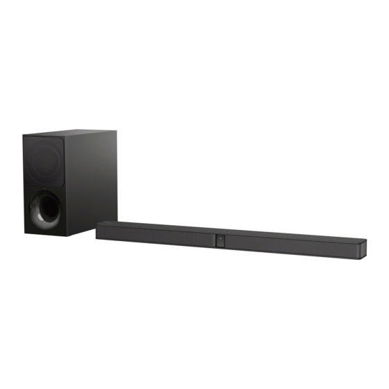
Sony HT-CT290 Service Manual

Sony HT-CT290 Service Manual

Sound bar and active speaker system
Hide thumbs Also See for HT-CT290:

Advertisement

SERVICE MANUAL
Ver. 1.0 2017.02
• All the units included in the HT-
CT290/CT291 (SA-CT290/CT291,
SA-WCT290/WCT291,
remote
control) are required to confi rm the
operation of SA-CT290/CT291.
Check in advance that you have
all the units.
Note:
Be sure to keep your PC used for service and
checking of this unit always updated with the
latest version of your anti-virus software.
In case a virus affected unit was found during
service, contact your Service Headquarters.
COMPONENT MODEL NAME
Bar Speaker (Active Speaker System)
Subwoofer (Active Subwoofer)
• The service manual for SA-WCT290/WCT291 has been issued separately.
Please refer to the service manual for information.
Bar Speaker (SA-CT290/
SA-CT291)
Amplifi er section
US models:
POWER OUTPUT AND TOTAL HARMONIC
DISTORTION:
(FTC)
Front L + Front R:
With 4 ohms loads, both channels
driven, from 200 Hz – 20,000 Hz;
rated 15 watts per channel minimum
RMS power, with no more than
1% total harmonic distortion from
250 milliwatts to rated output.
POWER OUTPUT (reference)
Front L/Front R: 100 W (per channel at
4 ohms, 1 kHz)
Other models:
POWER OUTPUT (rated)
Front L + Front R:
30 W + 30 W (at 4 ohms, 1 kHz, 1% THD)
POWER OUTPUT (reference)
Front L/Front R: 100 W (per channel at
4 ohms, 1 kHz)
Inputs
USB
TV IN OPTICAL
Output
HDMI OUT TV (ARC)
HDMI section
Connector
Type A (19pin)
USB section
(USB) port
Type A
9-890-685-01
Sony Corporation
2017B80-1
©
2017.02
Published by Sony EMCS (Malaysia) PG Tec
HT-CT290/CT291
Photo: SA-CT290 (Black)
Photo: SA-CT290 (White) / SA-CT291
HT-CT290
HT-CT291
SA-CT290
SA-CT291
SA-WCT290
SA-WCT291
SPECIFICATIONS
BLUETOOTH section
Communication system
BLUETOOTH Specification version
4.2
Output
BLUETOOTH Specifi cation Power
Class 1
Maximum communication range
Line of sight approx. 25 m (82 ft)
1)
Frequency band
2.4 GHz band (2.4000 GHz –
2.4835 GHz)
Modulation method
FHSS (Freq Hopping Spread
Spectrum)
Compatible BLUETOOTH profiles
2)
A2DP 1.2 (Advanced Audio
Distribution Profile)
AVRCP 1.6 (Audio Video Remote
Control Profile)
Supported Codecs
3)
SBC
4)
Transmission range (A2DP)
20 Hz – 20,000 Hz (Sampling
frequency 32 kHz, 44.1 kHz, 48 kHz)
1)
The actual range will vary depending on
factors such as obstacles between devices,
magnetic fields around a microwave
oven, static electricity, cordless
phone, reception sensitivity, antenna's
performance, operating system, software
application, etc.
2)
BLUETOOTH standard profiles
indicate the purpose of BLUETOOTH
communication between devices.
3)
Codec: Audio signal compression and
conversion format
4)
Subband Codec
HT-CT290/CT291/SA-CT290/CT291
Front L/Front R speaker section
Speaker system
Full range speaker system, Acoustic
suspension
Speaker
40 mm (1
5
/
in) × 100 mm (4 in) cone
8
type × 2
General
Power requirements
US, CND models:
120 V AC, 60 Hz
LA9 models:
110 V – 240 V AC, 50/60 Hz
EA models:
127 V – 240 V AC, 50/60 Hz
Other models:
220 V – 240 V AC, 50/60 Hz
Power consumption
On: 40 W
Standby: 0.5 W or less (Power saving
mode)
(When Control for HDMI function and
BLUETOOTH Standby mode are
set to off)
Standby: 2.8 W or less
5)
(When Control for HDMI function and
BLUETOOTH standby mode are set to
on)
Dimensions (w/h/d) (approx.)
900 mm × 52 mm × 86 mm
(35
1
/
in × 2
1
/
in × 3
1
/
in)
2
8
2
Mass (approx.)
2.3 kg (5 lb 2 oz)
5)
The system will automatically enter
Power saving mode when there is no
HDMI connection and no BLUETOOTH
pairing history.
ACTIVE SPEAKER SYSTEM
SA-CT290/CT291
US Model
Canadian Model
E Model
Australian Model
HT-CT290/SA-CT290
AEP Model
UK Model
Wireless transmitter/
receiver section
Frequency band
2.4 GHz (2.4000 GHz – 2.4835 GHz)
Modulation method
FHSS (Freq Hopping Spread
Spectrum)
Supplied accessories
Remote control (1)
R03 (size AAA) batteries (2)
Optical digital cable (1)
WALL MOUNT TEMPLATE (1)
Speaker pads for the subwoofer (4)
Refer to the supplied Operating Instructions on
installing the subwoofer horizontally.
Conversion Adaptor (2)
The adaptor is not use in Chile, Uruguay and
Paraguay. Use the adaptor in the countries
where it is neccessary.
Design and specifications are subject to
change without notice.
HT-CT290/CT291
SOUND BAR
SA-CT290/CT291

Advertisement

Table of Contents
loading

Summary of Contents for Sony HT-CT290

  • Page 1 Power saving mode when there is no Codec: Audio signal compression and HDMI connection and no BLUETOOTH USB section conversion format pairing history. (USB) port Subband Codec SA-CT290/CT291 Type A ACTIVE SPEAKER SYSTEM 9-890-685-01 Sony Corporation 2017B80-1 © 2017.02 Published by Sony EMCS (Malaysia) PG Tec...
  • Page 2 ® • The BLUETOOTH word mark and logos are registered trademarks owned by Bluetooth SIG, Inc. and any use of such marks by Sony SAFETY CHECK-OUT Corporation is under license. Other trademarks and trade names are those of their respective owners.
  • Page 3: Table Of Contents

    HT-CT290/CT291 TABLE OF CONTENTS SERVICING NOTES EXPLODED VIEWS ..........6-1. Overall Section ............... 35 DISASSEMBLY 6-2. Panel Section ..............36 6-3. Cabinet Assy Section ............37 2-1. Disassembly Flow ............6-4. Chassis Section ............... 38 2-2. Left, Right Panel (CG-BAR) ..........
  • Page 4: Servicing Notes

    Model Part No. CAPACITOR ELECTRICAL DISCHARGE PROCESSING HT-CT290 (Black): US CND 4-688-015-0[] When checking the board, for the electric shock prevention, con- HT-CT290 (Black): AEP 4-688-015-1[]...
  • Page 5 NOTE OF DISASSEMBLE PANEL, FRONT ERATION When disassemble the PANEL, FRONT, tweezer is required to All the units included in the HT-CT290/CT291 (SA-CT290/ remove cover and cover, screw. Remove through the service hole. CT291, SA-WCT290/WCT291, remote control) are required to confi...
  • Page 6 HT-CT290/CT291 Activating wireless transmission between specifi c units 1. SWITCHING REGULATOR 3L411L board (Secure Link) (US, CND) You can specify the wireless connection – SWITCHING REGULATOR 3L411L board to link the Bar Speaker to the subwoofer (US, CND) (Component Side) –...
  • Page 7 HT-CT290/CT291 3. SWITCHING REGULATOR 3L411W-1 board (E12) – SWITCHING REGULATOR 3L411W-1 board (E12) (Component Side) – *The portion which applies bond: SERVICE POSITION SWITCHING REGULATOR 3L411L (US, CND) SWITCHING REGULATOR 3L411W (EXCEPT US, CND, E12) SWITCHING REGULATOR 3L411W-1 (E12) MAIN board...
  • Page 8: Disassembly

    HT-CT290/CT291 SECTION 2 DISASSEMBLY • This set can be disassembled in the order shown below. 2-1. DISASSEMBLY FLOW 2-2. LEFT, RIGHT PANEL (CG-BAR) (Page 9) 2-3. DISP CHUKEI BOARD SECTION (Page 10) 2-4. CHASSIS SECTION (Page 10) 2-5. BLUETOOTH MODULE, MAIN BOARD (Page 11) 2-6.
  • Page 9: Left, Right Panel (Cg-Bar)

    HT-CT290/CT291 Note: Follow the disassembly procedure in the numerical order given. 2-2. LEFT, RIGHT PANEL (CG-BAR) 2 Insert the tweezer into the service hole and raise the cover, screw. service holes 4 one screw (TPP + 3 (HR) - 3W ZN)
  • Page 10: Disp Chukei Board Section

    HT-CT290/CT291 2-3. DISP CHUKEI BOARD SECTION 2 wire (flat type) (6 core) (CN5003) 4 two screws CASE 3 TP2 1 cushion, window 3 wire (flat type) (16 core) (CN5001) 5 DISP CHUKEI board section 2-4. CHASSIS SECTION 3 Insert the tweezer into the service hole and raise the cover (CG BAR).
  • Page 11: Bluetooth Module, Main Board

    HT-CT290/CT291 2-5. BLUETOOTH MODULE, MAIN BOARD Note 1: When the complete MAIN board is replaced, refer to Note 2: When the BLUETOOTH module is replaced, refer to “NOTES ON THE WIRELESS CONNECTION (LINK) “NOTES ON THE WIRELESS CONNECTION (LINK) AFTER REPAIRS ARE COMPLETE” on page 5.
  • Page 12: Test Mode

    HT-CT290/CT291 SECTION 3 TEST MODE RESET The reset clears certain data in this system without initialize Personal Information and some operation data. Execute this mode when returning the unit to the customers. Procedure: 1. Touch the [ ] touch key on the main unit to turn the power on.
  • Page 13 HT-CT290/CT291 5. Each time touch of any touch key in the set, the LED will display as below. The touch key which are already counted once are not counted again. Operation LED REACTION SPEC Transition Action MOVIE MUSIC BT LED...
  • Page 14 HT-CT290/CT291 Destination Indication Spec LED REACTION SPEC Action MOVIE MUSIC BT LED ......
  • Page 15 HT-CT290/CT291 Releasing method: Touch the [ ] touch key on the main unit or press the [ ] button on the remote commander to exit this mode. Touch again the [ ] touch key on the main unit or press again the [ ] button on the remote commander to reset the set.
  • Page 16 HT-CT290/CT291 3. In the state of step 2, press [PLAY MODE] button on the remote commander to swap speaker output. The LED will lights on as below table: Operation LED REACTION SPEC Transition Action MOVIE MUSIC BT LED ..
  • Page 17 HT-CT290/CT291 7. In the state of step 6, press [NIGHT] button on the remote commander to adjust the volume gain. It can be adjusted between +1.0 to -1.0 (decrease everytime 0.1 step). Eg: Refer to Gain Table as below: Operation...
  • Page 18 HT-CT290/CT291 Releasing method: Touch the [ ] touch key on the main unit or press the [ ] button on the remote commander to exit this mode. Touch again the [ ] touch key on the main unit or press again the [...
  • Page 19: Troubleshooting

    HT-CT290/CT291 SECTION 4 TROUBLESHOOTING...
  • Page 20 HT-CT290/CT291...
  • Page 21 HT-CT290/CT291...
  • Page 22 HT-CT290/CT291...
  • Page 23: Diagrams

    HT-CT290/CT291 SECTION 5 DIAGRAMS 5-1. BLOCK DIAGRAM - HDMI Section - HT-CT290/CT291...
  • Page 24: Block Diagram - Main Section

    HT-CT290/CT291 5-2. BLOCK DIAGRAM - MAIN Section - OPTICAL TV IN RECEIVER OPTICAL CN3400 BLUETOOTH >001B MODULE LRCK SECTION (Page 25) SERIAL FLASH IC2000 2 5 6 1 23 19 I2S_SDI DATA_C_SW I2S_WS (LRCK) MTK_I2S_OUT_LRCK I2S_SCLK (BCK) MTK_I2S_OUT_BCK CN7011 (USB)
  • Page 25: Block Diagram - Amp Section

    HT-CT290/CT291 5-3. BLOCK DIAGRAM - AMP Section - STREAM PROCESSOR DIGITAL POWER AMP IC1000 IC1001 L1009 PWM_P_2 41 INPUT_C OUT_C 32 R-CH L1010 PWM_M_2 40 INPUT_D OUT_D_27 >001B LRCK OUT_D_28 LRCLK PWM_P_4 49 INPUT_A MAIN L1007 SCLK PWM_M_4 48 INPUT_B...
  • Page 26: Block Diagram - Panel/Power Supply Section

    HT-CT290/CT291 5-4. BLOCK DIAGRAM - PANEL/POWER SUPPLY Section - SYSTEM CONTROLLER +1.2V REG. IC2003 (4/4) IC3209 +1.2V REMOTE CONTROL +3.3V POWER CONTROL +3.3V POWER CONTROL RECEIVER Q3204 Q2013 IC5001 PCONT_MAIN_SYSTEM 29 SIRCS_IN +5V REG. POWER CONTROL IC3200 SWITCHING REGULATOR Q3203 3L411W +12V REG.
  • Page 27 HT-CT290/CT291 THIS NOTE IS COMMON FOR PRINTED WIRING BOARDS AND SCHEMATIC DIAGRAMS. • Circuit Boards Location (In addition to this, the necessary note is printed in each block.) For Printed Wiring Boards. For Schematic Diagrams. SWITCHING REGULATOR 3L411L (US, CND)
  • Page 28: Printed Wiring Board - Main Board (Component Side)

    HT-CT290/CT291 5-5. PRINTED WIRING BOARD - MAIN Board (Component Side) - • See page 27 for Circuit Boards Location. • : Uses unleaded solder. MAIN BOARD (COMPONENT SIDE) CONNECT TO USB BOARD SWITCHING REGULATOR 3L411W (EXCEPT US, CND, E12) CN7010...
  • Page 29: Main Board (Conductor Side)

    HT-CT290/CT291 5-6. PRINTED WIRING BOARD - MAIN Board (Conductor Side) - • See page 27 for Circuit Boards Location. • : Uses unleaded solder. MAIN BOARD (CONDUCTOR SIDE) FLASH PROGRAMMING (CHASSIS) CL2124 CL2122 CN2008 CL2126 CL2123 CL2125 R3005 CL2140 R3026...
  • Page 30: Printed Wiring Board - Disp Chukei Board

    HT-CT290/CT291 5-7. PRINTED WIRING BOARD - DISP CHUKEI Board - • See page 27 for Circuit Boards Location. • : Uses unleaded solder. DISP CHUKEI BOARD DISP CHUKEI BOARD (COMPONENT SIDE) (CONDUCTOR SIDE) TOUCH BOARD MAIN BOARD CN4001 CN2006 (Page 31) (Page 28) >003P...
  • Page 31: Printed Wiring Board - Touch Board

    HT-CT290/CT291 5-8. PRINTED WIRING BOARD - TOUCH Board - • See page 27 for Circuit Boards Location. • : Uses unleaded solder. TOUCH BOARD (COMPONENT SIDE) JL4005 R4003 JL4003 R4002 JL4004 JL4001 JL4002 IC4001 R4010 R4001 R4013 C4001 R4014 C4000...
  • Page 32: Schematic Diagram - Touch Board

    HT-CT290/CT291 5-9. SCHEMATIC DIAGRAM - TOUCH Board - • See page 34 for IC Block Diagrams. • See page 34 for IC Pin Function Description. TOUCH BOARD IC4002 PST8429UL C4000 IC4002 R4005 R4007 R4014 0.0022u 5.6k VOLTAGE DETECT C4001 0.1u 1.8 1.3...
  • Page 33: 5-10. Printed Wiring Board - Usb Board

    HT-CT290/CT291 5-10. PRINTED WIRING BOARD - USB Board - 5-11. SCHEMATIC DIAGRAM - USB Board - • • See page 27 for Circuit Boards Location. : Uses unleaded solder. USB BOARD (COMPONENT SIDE) USB BOARD MAIN BOARD CN7010 CN3000 (Page 28) >001P...
  • Page 34 HT-CT290/CT291 • IC Block Diagrams • IC Pin Function Description IC4002 PST8429UL (TOUCH BOARD) TOUCH BOARD IC4001 CY8CMBR3108-LQXIT (TOUCH KEY CONTROLLER) Pin No. Pin Name Description GND 1 1, 2 CS0/PS0, CS1/PS1 Fixed at “L” in this unit CMOD External capacitor connection terminal...
  • Page 35: Exploded Views

    HT-CT290/CT291 SECTION 6 EXPLODED VIEWS Note: • -XX and -X mean standardized parts, so • Abbreviation The components identifi ed by mark 0 they may have some difference from the : Australian model or dotted line with mark 0 are critical for original one.
  • Page 36: Panel Section

    HT-CT290/CT291 6-2. PANEL SECTION Ref. No. Part No. Description Remark Ref. No. Part No. Description Remark 4-685-629-01 SCREW, +B P2X6 4-685-615-11 GRILLE, SIDE (CG-BAR) (for White model) 4-591-760-01 TPP + 3X10 (HR) - 3W ZN 4-587-762-11 GASKET, P 1-859-199-11 LOUDSPEAKER (35*93MM)
  • Page 37: Cabinet Assy Section

    HT-CT290/CT291 6-3. CABINET ASSY SECTION chassis section Note: If wire (fl at type) is replaced, install it after bending it in the same form as that before replacement. Ref. No. Part No. Description Remark Ref. No. Part No. Description Remark...
  • Page 38: Chassis Section

    HT-CT290/CT291 6-4. CHASSIS SECTION Note 1: If wire (fl at type) is replaced, install it after bending it in the Note 3: When the BLUETOOTH module is replaced, refer to same form as that before replacement. “NOTES ON THE WIRELESS CONNECTION (LINK) Note 2: When the complete MAIN board is replaced, refer to AFTER REPAIRS ARE COMPLETE”...
  • Page 39: Electrical Parts List

    HT-CT290/CT291 SECTION 7 DISP CHUKEI MAIN ELECTRICAL PARTS LIST TOUCH Note: • Due to standardization, replacements in • SEMICONDUCTORS The components identifi ed by mark 0 the parts list may be different from the In each case, u: μ, for example: or dotted line with mark 0 are critical for parts specifi...
  • Page 40 HT-CT290/CT291 TOUCH Ref. No. Part No. Description Remark Ref. No. Part No. Description Remark < IC > ACCESSORIES ************ IC4001 6-722-496-01 IC CY8CMBR3108-LQXIT IC4002 6-713-333-01 IC PST8429UL 4-688-252-12 MANUAL, INSTRUCTION (ENGLISH (US), CANADIAN FRENCH, SPANISH) < JUMPER CHIP > (US, CND)
  • Page 41 HT-CT290/CT291 MEMO...
  • Page 42 HT-CT290/CT291 REVISION HISTORY Ver. Date Description of Revision 2017.02 How to search for a contact point of signal lines or the like in DIAGRAMS SECTION If a contact point of a BLOCK DIAGRAM, PRINTED WIRING BOARD or SCHEMATIC DIAGRAM is shown in a different page, use the PDF fi...

This manual is also suitable for:

Ht-ct291Sa-ct290Sa-ct291Sa-wct290Sa-wct291

Table of Contents